EP3045332B1 - Buse d'air - Google Patents
Buse d'air Download PDFInfo
- Publication number
- EP3045332B1 EP3045332B1 EP15202432.9A EP15202432A EP3045332B1 EP 3045332 B1 EP3045332 B1 EP 3045332B1 EP 15202432 A EP15202432 A EP 15202432A EP 3045332 B1 EP3045332 B1 EP 3045332B1
- Authority
- EP
- European Patent Office
- Prior art keywords
- socket
- air nozzle
- section
- joint
- sleeve
- Prior art date
- Legal status (The legal status is an assumption and is not a legal conclusion. Google has not performed a legal analysis and makes no representation as to the accuracy of the status listed.)
- Active
Links
Images







Classifications
-
- B—PERFORMING OPERATIONS; TRANSPORTING
- B60—VEHICLES IN GENERAL
- B60H—ARRANGEMENTS OF HEATING, COOLING, VENTILATING OR OTHER AIR-TREATING DEVICES SPECIALLY ADAPTED FOR PASSENGER OR GOODS SPACES OF VEHICLES
- B60H1/00—Heating, cooling or ventilating devices
- B60H1/34—Nozzles; Air-diffusers
- B60H1/3414—Nozzles; Air-diffusers with means for adjusting the air stream direction
- B60H1/3435—Nozzles; Air-diffusers with means for adjusting the air stream direction using only a pivoting frame
- B60H1/3442—Nozzles; Air-diffusers with means for adjusting the air stream direction using only a pivoting frame the frame being spherical
-
- B—PERFORMING OPERATIONS; TRANSPORTING
- B60—VEHICLES IN GENERAL
- B60H—ARRANGEMENTS OF HEATING, COOLING, VENTILATING OR OTHER AIR-TREATING DEVICES SPECIALLY ADAPTED FOR PASSENGER OR GOODS SPACES OF VEHICLES
- B60H1/00—Heating, cooling or ventilating devices
- B60H1/34—Nozzles; Air-diffusers
- B60H2001/3464—Details of hinges
-
- B—PERFORMING OPERATIONS; TRANSPORTING
- B60—VEHICLES IN GENERAL
- B60H—ARRANGEMENTS OF HEATING, COOLING, VENTILATING OR OTHER AIR-TREATING DEVICES SPECIALLY ADAPTED FOR PASSENGER OR GOODS SPACES OF VEHICLES
- B60H1/00—Heating, cooling or ventilating devices
- B60H1/34—Nozzles; Air-diffusers
- B60H2001/3471—Details of actuators
- B60H2001/3478—Details of actuators acting on additional damper doors
-
- B—PERFORMING OPERATIONS; TRANSPORTING
- B64—AIRCRAFT; AVIATION; COSMONAUTICS
- B64D—EQUIPMENT FOR FITTING IN OR TO AIRCRAFT; FLIGHT SUITS; PARACHUTES; ARRANGEMENT OR MOUNTING OF POWER PLANTS OR PROPULSION TRANSMISSIONS IN AIRCRAFT
- B64D13/00—Arrangements or adaptations of air-treatment apparatus for aircraft crew or passengers, or freight space
- B64D2013/003—Cabin ventilation nozzles
Definitions
- the present invention relates to an air nozzle comprising at least one articulated connection.
- Conventional air nozzles for ventilating the vehicle interior are known from the state of the art, in which the air guide elements, which are often constructed as lamellae, are designed to be horizontally or vertically adjustable in order to control the ventilation flow into the vehicle interior in a controlled manner. If, on the other hand, the air flow is to be completely interrupted, it requires the actuation of a further switching element, usually in the form of a setting wheel. Consequently, a variety of different components is required for known air nozzles, which are all to be matched. Therefore, the production cost is relatively complex and costly.
- WO 00/63037 A1 discloses a ventilation device for a vehicle with a tubular air duct, in which a ventilation body is pivotably mounted on a central portion of a first disc.
- the disc has openings and is rotatably mounted so that the openings can be aligned with further openings of a second parallel disc to provide an air flow.
- the central portion extends from the first disc and has a connecting portion for the ventilation body at its protruding end.
- the connecting portion has a polygonal opening in which a control element is received with a corresponding portion for rotating the first disc.
- the central portion is hollow and is mounted on a bearing journal of the second discs and connected via a detent in the connecting portion with the first discs.
- GB 1 310 493 A discloses also a ventilation device with a tubular air duct, wherein a star-shaped ventilation element is coupled via a rod and a first ball joint and a second ball joint with a closing flap.
- the ventilation element is rotatably mounted, wherein a rotation of the ventilation element causes a pivoting of the closing flap.
- the object of the present invention is to provide an air nozzle in which the rattle and movement force can be adjusted without far-reaching coordination of the individual component components. Furthermore, it is also an object of the present invention to provide an air nozzle with a reduced number of components and with subsequently adjustable operating forces.
- the air nozzle according to the invention according to claim 1 proves to be advantageous because it has a manageable number of parts, a simple operation for adjusting the exiting air flow, a reduction of the tuning loops in the industrialization of the tools and a fast response or Modification of the operating forces depending on the customer's request allows.
- the present invention comprises an air nozzle, which comprises at least one air nozzle housing, which is designed for at least partially receiving a joint socket section, wherein the air nozzle housing comprises at least one sleeve-like section for at least partially receiving the joint socket section, furthermore at least one attachment element for directing an outgoing air stream, which at least one
- the condyle further comprises a socket portion having at least one socket for at least partially receiving the condyle, and an adjoining extension portion at a first free end, the extension portion being adapted to be at least partially disposable in the sleeve portion of the air nozzle housing and Condyle and socket are designed as articulated connection.
- the air nozzle comprises a fastening element for fixing the socket portion in the sleeve-like portion, wherein the extension portion has at least one material taper at its free end opposite the socket.
- the fastening element can be plugged onto the material taper and on the at least one projection.
- the air nozzle according to the invention is designed in particular for guiding air streams for heating, air conditioning or ventilation systems in motor vehicles and to use for this purpose.
- the air nozzle advantageously comprises at least one air nozzle housing and / or a receptacle, which can be arranged in an air nozzle housing, which is (s) further advantageously for at least partially receiving the first joint element, which is advantageously designed as a joint socket and / or joint socket portion is formed.
- the air nozzle housing forms a first basic component of the air nozzle described here. It represents the connection between the air nozzle and the motor vehicle and is designed, for example, connectable to a dashboard of a motor vehicle.
- the ventilation of the vehicle interior air flow enters from the back of the air nozzle housing in this.
- the back side is to be understood advantageously the built-in side, with which the air nozzle is connected for example to heating, air conditioning or ventilation systems of a motor vehicle. It is quite common for the lateral areas of the air nozzle housing to be protruding from the dashboard, for example.
- the air nozzle housing and / or the receptacle for fixing to the housing further comprises a sleeve-like portion, which is also advantageously centered centered.
- the sleeve-like portion is at least partially hollow and serves for at least partially receiving the socket portion.
- the joint socket section is at least partially insertable and / or lockable in the sleeve-like section of the air nozzle housing.
- the sleeve-like portion is formed as a coupling element between the air nozzle housing and the socket portion.
- the sleeve-like portion is integrally formed with the air nozzle housing, for example, produced in an injection molding process or else glued to the air nozzle housing or the like.
- the sleeve-like portion is detachably arranged on the air nozzle, for example attachable.
- the sleeve-like portion may be provided as a separate component, for example as an insert element.
- the joint socket section comprises at least one socket for at least partially receiving the condyle of the attachment element at a first free end. Furthermore, an extension section connects to the socket, so that the socket section is advantageously formed in one piece.
- the extension portion is formed in its geometry such that it can be arranged at least partially in the sleeve-like portion of the air nozzle housing or the receptacle.
- it is variably formed in its outer diameter.
- it is designed such that it is largely, advantageously completely, inserted into the sleeve-like portion formed as at least partial hollow body. Consequently, the outer diameter of the extension portion is advantageously smaller than the inner diameter of the sleeve-like portion.
- the extension portion is formed of an elastic and / or deformable material, for example of an elastomer such as rubber or rubber. Then, the extension portion is applied upon insertion into the sleeve-like portion with a compressive force, which leads to its deformation. However, if the extension portion is disposed at the predetermined depth within the sleeve-like portion, the elastic material may accordingly expand again and thus form a fixation and support.
- the air nozzle described here comprises at least one attachment element, which may further comprise at least one air guide element.
- the attachment element has a plurality of air guide elements, which are formed in the simplest case as lamellae. It has in the present air nozzle as proved advantageous that the air guide elements are formed radially diverging.
- the attachment element serves to direct the direction of the exiting air flow, for example in a vehicle interior.
- the attachment element further comprises, on the side facing away from the vehicle interior, at least one joint element, for example a joint head.
- the joint head is centered and / or arranged centrally on the attachment element.
- the two joint elements - condyle and socket and / or condyle and socket section - are in operative connection with each other, so that a coupling between attachment element and air nozzle housing is formed.
- the condyle is at least partially disposed within the socket and / or rotatably disposed within the socket.
- joint connection is on the other hand formed by a joint socket (first ball joint) on the one hand and by a joint head (second ball joint).
- first ball joint first ball joint
- second ball joint second ball joint
- first joint element and second joint element are in operative connection.
- the condyle is advantageously at least partially disposed within the socket and is advantageously held by this.
- the actuation force of the attachment element is adjustable. If the articulation is designed as a ball joint, it is a three-axis joint with the highest degree of freedom.
- the operative connection of the ball joint takes place through the interaction of the condyle and the socket, wherein the condyle is at least partially disposed within the socket and is at least partially surrounded by it.
- the grasping takes place in such a way that the condyle is held in the desired range of movement within the socket by the latter and an undesired slipping out is prevented.
- the ball joint connection is the possibility of the attachment element, which via the hinge connection At least partially disposed within the air nozzle housing, to adjust as desired, without causing an undesirable lateral outlet of the leading air flow.
- the attachment element arranged at least partially within the joint socket can be rotated around the ball head. It only affects the outer wall of the air nozzle housing as a limiting factor of movement.
- the mobility of the attachment element within the air nozzle housing is significantly increased, so that the exiting the air nozzle in the vehicle interior airflow can be guided easier and more controllable.
- the condyle is connected in an advantageous embodiment fixed to the essay, for example, formed in a single manufacturing step.
- the attachment element is arranged pivotably and freely rotatable in any direction over the joint head within the joint socket.
- the attachment element in the developed state of the articulated connection between the condyle and the socket is arranged at least partially within the air nozzle housing, so that even with the greatest possible Pivoting the attachment element no lateral gap between air nozzle housing and attachment element conditionally, through which the air flow can escape uncontrollably and undesirable.
- the condyle at least as a hemisphere, more preferably as a three-quarter sphere.
- the three-quarter ball is advantageous for the freedom of movement of the attachment element element.
- the air nozzle also has the fastening element for fixing the attachment element with the air nozzle housing. This is advantageous since the at least one fastening element allows a controllable engagement of the condyle and the socket. With the help of the fastener, the actuation force of the attachment element is adjusted.
- At least one fastening element serves to (releasably) fix the joint socket section, more precisely the extension section, within the sleeve-like section.
- the fastener is also adapted to releasably dispose and fix both the socket portion and the sleeve-like portion on the air nozzle housing.
- This fixation is also the setting of the actuation force of the attachment element at the same time.
- the fastener from the back of the air nozzle housing is insertable.
- the air nozzle housing has a continuous opening through which the at least one fastening element is guided.
- this opening in the air nozzle housing is congruent with a corresponding opening of the sleeve-like portion.
- the extension portion of the socket at its free end opposite the socket has at least one material taper, wherein the material taper is fixedly arranged on the extension portion, advantageously formed integrally therewith.
- the material taper is formed as a cylindrical extension of the extension portion and extends in the longitudinal direction of the extension portion. The material taper can be passed through the openings of the sleeve-like portion and the back of the air nozzle housing and is beyond the latter.
- the extension portion itself has no opening for insertion of a fastener.
- the cylindrical material taper is advantageously arranged such that it is feasible through the two congruent openings of air nozzle housing and sleeve-like section.
- the joint socket section with implementation of the material taper is still arranged loosely in the sleeve-like section.
- the material taper comprises at least one projection.
- two projections are arranged at the same height and each extend radially outward.
- the two projections are arranged offset to one another in the longitudinal direction of the material taper. It is also conceivable to provide more than two projections, for example three to six.
- the fastening element is formed attachable to the material taper and the at least one projection. This is advantageous in order likewise to reduce the diameter of the joint socket, advantageously indirectly and / or directly. Here, it has proved to be advantageous to provide a fine catch as a fastening element, so that the torque generated is definable.
- the fixing element is designed as a nut.
- the formulations fixing element and fastener are used synonymously.
- the fastener is first attached after the arrangement of the socket portion in the sleeve-like portion on the material taper.
- the fastening element in addition to the central opening, through which it can be plugged onto the material taper, at least one further opening, advantageously also a plurality of openings, through which the at least one projection of the material taper is at least insertable and / or feasible.
- the fastener is aligned when plugging on the material taper depending on the projections such that at least one projection can be inserted and / or passed through a further opening provided therefor.
- the extension portion has a further, advantageously congruent opening as the sleeve-like portion.
- the sleeve-like portion is formed conically and / or convexly and / or concavely curved at a free end.
- the free end is in this case arranged at the opposite free end of the sleeve-like portion, which is opposite to the opening for insertion of the fastening element.
- the socket portion is at least partially disposed in the sleeve-like portion of the air nozzle housing.
- the socket is at least partially encompassed by the sleeve-like portion. It is also conceivable that a gap is formed between the sleeve-like section and the socket. This is for the alignment of the socket advantageous.
- the sleeve-like portion thus has a similar geometric configuration as the socket portion.
- the sleeve-like section has at its free end an at least partially conical and / or convex and / or concave curved area.
- the free end of the sleeve-like portion encloses the at least partially disposed socket.
- the joint socket is directly and / or indirectly changeable in its diameter.
- the actuating force with which the attachment element is advantageously at least partially rotatable within the air nozzle housing and with which the exiting air flow can be directed in the vehicle interior, via the hinge connection, advantageously via the ball joint, advantageously over the changed outer and / or inner diameter of the Joint socket to control.
- This change in the diameter, in particular of the inner diameter of the socket, is advantageous in order to set the actuating force of the attachment element individually.
- the diameter of the socket is too large compared to the diameter of the at least partially spherical condyle, so the condyle slides within the socket and there is no operative connection between the two joint elements.
- the air nozzle is not functional.
- the diameter, in particular the inner diameter of the socket selected too small, so there is a risk that the joint head on the one hand is not inserted into the socket or that, on the other hand, the condyle is so firmly enclosed by the socket, so that although an operative connection is formed, but a free mobility of the condyle is prevented. Both speak against the functionality of the air nozzle described here.
- the joint socket at least one in the longitudinal extension of the joint socket portion having extending opening.
- several of these openings for example, two to eight, provided. Between these openings wall portions are formed, which are designed deflectable upon application of force.
- the intervening openings which are advantageously slit-like, cause free spaces, in which the wall sections can be brought upon application of force. In this way, a reversible reduction of the outer and / or inner diameter of the socket can be formed in a skilful manner, without causing material cracks or overstress.
- the change of the diameter in particular of the inner diameter of the socket, can be direct and / or indirect.
- a direct change for example, it is conceivable to design the inner diameter of the joint socket in such a way that the joint head can be pressed into the joint socket via expansion of the wall regions via a pressure force application, so that a click or snap connection results.
- This connection represents the simplest connection between the condyle and the socket. To adjust the actuation force, the fastener is then attached, as described in detail above.
- the rotation and / or the displacement of the attachment element can be addressed directly to the preferences of the user by the rotation and / or the displacement of the attachment element and thus the direction of the air flow, for example, very easily or can be very difficult.
- the fastening element is designed such that the actuating force of the attachment element is designed to be adjustable and that this adjustment is made from below, advantageously from the rear side of the air-jet housing.
- At least one guide groove is additionally provided within the fastening element.
- This guide groove is advantageous if the fastener is subjected to a rotational force. Then, during the rotational movement of the fastening element, the at least one projection is guided along within this guide groove.
- the at least one guide groove describes a spiral shape.
- the fastening element is designed as a clamping element.
- no separate nut is provided.
- the fastener is already integrated with the socket section.
- the clamping element is formed in the simplest case as a spring element.
- the air nozzle further comprises at least one closing element.
- the closing element is designed such that it is designed to be movable and / or rotatable in its position, depending on the operation of the attachment element. When moving the attachment element at the same time a coupled movement of the closing element is generated.
- the exiting air flow from the air nozzle can be controlled and completely prevented, for example.
- the closing element is formed connected via at least one coupling element and / or at least one adjusting element with an insert element and / or the sleeve-like portion.
- the closing element is provided as a double element, for example as a butterfly element.
- the closing element is advantageously connected via at least one adjusting element, for example a toothed wheel, with at least one coupling element.
- the coupling element comprises at least one, advantageously a plurality of circumferentially arranged openings.
- the insert element comprises in its longitudinal direction at least one latching element, which is designed such that it engages in the at least one opening of the coupling element.
- the joint socket section is arranged here in an insert element which corresponds in its properties to the properties of the sleeve-like section, as likewise described above.
- the insert element has at least one, advantageously several latching elements, which are inserted into the respectively provided peripheral openings of the coupling element and locked it. As a result, a fixation of coupling with insert element is formed.
- the coupling element and / or insert element in the mutually arranged state are at least partially rotatable together about the longitudinal axis of the air nozzle.
- the attachment element is actuated, for example, rotated, this rotational movement is forwarded to the attachment element and coupling element. Both elements also rotate.
- the adjusting element is also set in rotary motion, which pivots about the gear connection, the closing element in its position, so that closes the closing element and the air flow is interrupted.
- the joint head comprises at least one projection.
- at least two pin-like projections are provided on the joint head, which are further advantageously formed opposite each other, extending radially outwardly. Both projections are arranged in two, complementary thereto designed openings of the socket. These two openings are then only limited to change the outer and / or inner diameter of the socket.
- the projections are for the leadership of the ball and / or the condyle of advantage.
- the pin-like projections prove as advantageous because they form a limitation of the rotational movement of the attachment element and thus at the same time facilitate the control of at least one closing element significantly.
- At least one braking element for example a plastic ring, which is at least partially disposed above the coupling element and / or at least partially disposed within the coupling element to provide.
- the acting force for adjusting the closing element can be controlled.
- At least one spacer element for example a washer, is provided between the fastening means and the air nozzle housing.
- This washer is advantageously further formed as a locking washer to prevent release of the fastener.
- the air nozzle according to the invention as a ball air nozzle in motor vehicle interiors, in particular for heating, air conditioning and / or ventilation systems.
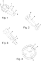
- a socket portion 1 with partially inserted fastener 2 and securing element 3 is shown.
- the securing element 3 corresponds to a spacer element.
- the joint socket section 1 has at its upper free end the socket 4, on which the extension section 8 adjoins the longitudinal side.
- the joint socket 4 has, as an example, four openings 6, which likewise extend in the longitudinal direction of the socket section 1.
- the socket is at least partially curved, advantageously pan-like and / or at least partially open like a spherical shell upward and / or convexly curved, so that an at least partially spherical trained condyle (not shown) in the socket 4 can be inserted and fixed.
- At least one fastening element 2 is provided at the free end of the extension section 8, which is arranged opposite the joint socket. In the simplest case, this is designed as a screw.
- FIG. 2 another view of a socket portion 1 of Fig. 1 shown, in which in particular the fastening element 2 and the securing element. 3 are visible.
- the fastener 2 is inserted from below, so at the opposite end of the socket 4 free end of the extension portion 8 through the opening in this.
- the securing element 3 is advantageously designed as a spacer ring made of elastic material, for example rubber.
- the two arrow directions indicate that the fastening element 2 is rotated into the extension section 8, so that the fastening element 2 gradually inserts into the recess of the extension section 8.
- the fuse element 3 is provided.
- This representation is to be understood as an example. The same mechanism takes place in the fixation in the sleeve-like portion (not shown).
- Fig. 4 is a plan view of the socket 4 shown, in which the axis of rotation R corresponds to the longitudinal axis of the socket portion 1.
- the openings 6 of the socket 4 are here uniformly spaced from each other.
- the number 4 of the openings 6 is not to be understood as limiting, so that quite a larger number of openings 6 can be provided, for example 5 to 12.
- Fig. 5 is a perspective view of the socket portion 1 without fastener with the opening in the extension portion 8 is shown.
- the opening is introduced at the opposite end of the socket 4 of the extension portion 8 and extends as a recess 10 at least partially within the extension portion 8.
- the fastener as shown in the preceding figures, in the Extension section 8 insertable.
- the recess has at least one internal thread and / or another fixing mechanism, by means of which the fastening element (not shown) is releasably fixable in the recess, for example, can be clicked, screwed, latched or the like.
- Fig. 6 is the corresponding sectional view of the socket portion 1 of Fig. 5 shown where in particular the recess 10 is shown.
- the recess 10 in a different longitudinal direction extension, that is to provide it shorter or longer than shown.
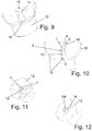
- a top view of an exemplary air nozzle housing 12 is shown.
- the sleeve-like portion 14 is shown centrally disposed on the bottom surface of a further opening 16 is formed.
- This further opening 16 serves to pass the fastening element (not shown) and fix the socket section (not shown) to the sleeve-like section 14.
- the air nozzle housing 12 is at least partially spherical, advantageously hemispherical, formed. This is especially true in Fig. 8 and 9 clearly, which also shows an air nozzle housing 12 in cross section.
- the air nozzle housing 12 has a cylindrical portion and an upwardly curved portion 13 expanding. In this upwardly curved extended portion 13 of the sleeve-like portion 14 is arranged.
- On the underside of the opening 16 for performing the fastener (not shown) is formed. So that the extension section 8 takes place by the rotation of the fastener 2 in the sleeve-like portion, the air nozzle housing 12 in the region of the opening 16 has a sufficient wall, so that the fastener itself is not screwed further than up to this wall. This has the consequence that with further screwing of the fastening element 2, this pulls the extension section 8 in the direction of the wall. The extension portion 8 is thus retracted into the sleeve-like portion against the wall.
- Fig. 8 is a further perspective view of the air nozzle housing 12 is shown, wherein the air nozzle housing 12 described here is advantageously used for ball air nozzles.
- the sleeve-like portion 14 is arranged centrally within the air nozzle housing 12 and has a likewise upward opening 15. In this opening 15 of the joint socket portion (not shown) is at least partially inserted.
- the opening 15 of the sleeve-like portion 14 is conical and has a tapering in the direction of opening 16 cross-section.
- this conical design is advantageous for setting the attachment element torque.
- FIG. 10 an enlarged sectional view of the air nozzle housing 12 is shown with the joint socket portion 1 arranged therein.
- the opening 16 of the air nozzle housing 12 is in this Case still exposed, so freely provided.
- In the sleeve-like portion 14 of the socket portion 1 is at least partially inserted.
- the extension section 8 is arranged almost completely in the sleeve-like section 14.
- the recess 10 of the extension portion 8 is congruent with the opening 16 of the air nozzle housing 12, which is also the opening of the sleeve-like portion 14 is formed, so that if necessary, the fastener (not shown) can be inserted both through the opening 16 and into the recess 10 and / or lockable, for example screwed.
- a free volume F is provided, which is reduced upon actuation of the fastener (not shown) and the joint socket portion 1 is guided in the direction of the opening 16.
- the upper free end of the socket 4 forms a common plane with the free upper end of the air nozzle housing 12.
- the socket 4 is arranged below this plane.
- a gap S results between the upper free end region of the sleeve-like portion 14, which is arranged adjacent to the joint socket 4.
- This gap S is advantageously a conical and / or curved design of the upper free end of the sleeve-like portion 14 conditionally.
- This advantageous conical and / or convexly curved design it is possible, the joint cup portion 1 in the sleeve-like portion 14 under Switzerlandkraft- and / or Druckkraftbeetzschlagung introduce.
- both the outer and the inner diameter of the socket 4 is changed, so that the holding force for the condyle, not shown, is variable.
- Fig. 11 is the corresponding three-dimensional representation of the Fig. 10 shown again.
- Fig. 12 Again, the gap S between the socket 4 and sleeve-like section 14 can be clearly seen.
- Fig. 13 the underside of the air nozzle housing 12 is shown with the joint socket section 1 arranged therein.
- the already introduced fastener 2 is shown here.
- a further component of the air nozzle is shown, namely the attachment element 18.
- the attachment element 18 is annularly curved, advantageously convexly curved, formed and has a plurality of air guide elements 20, which are formed as a radial blades. Centric, advantageously along the axis of rotation R, the condyle 22 is fixedly arranged on the attachment element 18.
- the condyle 22 is formed almost spherical and has only at one area the connection with the attachment element 18.
- Fig. 15 shows the attachment of Fig. 14 in a further perspective view.
- Fig. 16 Furthermore, an attachment element 18 with joint socket section 1 arranged thereon is shown.
- the condyle 22 is already disposed within the socket 4, for example, snapped or otherwise fixed.
- FIG. 17 shown view shows an air nozzle 28, in which on the air nozzle housing 12 already the attachment element 18 is arranged thereon with the socket portion 1 in the sleeve-like portion 14 of the air nozzle housing 12 and is fixed from below with the fastener 2.
- the attachment element 18 is at least partially disposed within the air nozzle housing 12, wherein a range of motion of the attachment element 18 is ensured.
- a corresponding exploded view of an embodiment of an air nozzle 28 is shown.
- the air nozzle housing 12 with the sleeve-like portion 14 serves to receive the socket portion 1, the socket 4 is in turn formed for receiving the condyle 22 of the attachment member 18.
- a fixation is carried out only by the fastening element 2, which additionally may have a securing element 3, for example a sealing washer.
- the fastening element 2 is inserted from the rear, ie from the cylindrical part of the air nozzle housing 12, through the sleeve-like section 14 into the recess 10 of the extension section 8 and screwed tight.
- the socket portion 1 is retracted into the sleeve-like portion 14, so that at the same time reduces the outer and / or inner diameter of the socket 4 and the range of motion of the condyle 22 disposed therein is reduced. This causes an increased operating force when exiting from the attachment element Air flow, for example, to be directed to the window.
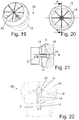
- Fig. 19 is a three-dimensional representation of in Fig. 17 shown air nozzle 28 shown for clarity. Due to the curved design of the attachment element 22 and the air nozzle housing 12, it is possible for the attachment element 18 to rotate about the articulation at least partially within the air nozzle housing 12 and to move.
- Fig. 20 is a plan view of an air nozzle 28 is shown, wherein the sectional area AA in Fig. 21 is explained schematically.
- introduced fastener 2 rotates, for example, is screwed, and so the extension portion and at the same time the entire joint cup portion 1 is retracted into the sleeve-like portion 14 ,
- pressure P there is the application of pressure P on the condyle 22, since the socket 4 is reduced in its inner diameter and consequently surrounds the condyle 22 fixed.
- Fig. 22 this is shown again in a further sectional view, in which case the fastening element 2 is already introduced into the recess 10 of the extension section 8, but there is still a clear free volume F between the extension section 8 and the sleeve-like section 14. Consequently, the socket portion 1 can be further inserted into the sleeve-like portion 14. Now, if the fastener 2 is further actuated, that is screwed into the recess 10 of the extension portion 8, so decreases the free volume F and the socket portion 1 is sunk in the sleeve-like portion 14.
- FIG. 23 Furthermore, a sectional view of an air nozzle 28 is shown, in which it can be seen that the articulation of the air nozzle 28, formed from condyle 22 and socket 4 is a ball joint, which allows the rotation of the attachment element in any direction.
- the actuating force of the attachment element 18 is adjusted.
- a joint socket portion 1 according to the invention is shown, which dispenses with a separately insertable fastener.
- a material taper 30 is fixedly arranged on the free side of the socket 4.
- This material taper 30 additionally has at least one projection 32, advantageously two projections 32 lying opposite one another.
- another additional fastening element 34 is provided here, which is slid over at least one of the two, advantageously over both projections 32, in order then to lock accordingly (shown in FIG Fig. 24c ).
- the fastening element 34 may be formed as a ring and / or disc.
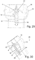
- the reduction of the inner diameter of the socket 4 is effected by the fastening element 34 from below in the cylindrical portion of the air nozzle housing (not shown) on the material taper 30 and / or at least one projection 32 plugged (shown in FIG Fig. 27 ) and, as in Fig. 28 - 30 shown, advantageously rotated by 90 °.
- the fastening element 34 is guided against the delimiting wall of the air nozzle housing 12 and thus pulls the joint socket section 1 downwards in the direction of the cylindrical section of the air nozzle housing 12.
- the free volume F described above also decreases here.
- FIGS. 25 and 26 A corresponding arrangement with the attachment element 18 and the further alternative of the joint socket section 1 is shown in FIGS. 25 and 26 shown.
- the fastening element 34 has at least one inner guide groove, in which at least one projection 32 can be guided. As a result, additional locking positions are possible in order to adjust the torque of the attachment element (not shown) accordingly.
- a closing element 40 is additionally provided.
- This closing element 40 is connected to an adjusting element 42, wherein the adjusting element 42 may be formed, for example, as a conical gear.
- the actuator 42 is arranged on a coupling element 38 and interacts with likewise toothed wheels formed areas of the closing element 40th
- the coupling element 38 has at least one circumferential opening 48 into which in each case a latching element 46 of the insert element 52 engages and is secured (see FIG Fig. 34 ).
- the coupling element 38 additionally serves as connection of the adjusting element 42 with the closing element 40.
- a further insert element 52 is provided here, which replaces the original sleeve-like section 14.
- the insert element 52 advantageously has a plurality of nose-like latching elements 46, which are insertable and lockable into correspondingly provided openings 48 of the coupling element 38. Consequently, the insert element 52 can be inserted into the coupling element 38.
- the fastening element 2 is arranged within the insert element 52, which in turn can be inserted into the joint socket section 1, as also described above.
- Fig. 31 is a plan view of the further embodiment of an air nozzle 28 is shown, wherein in Fig. 32 the cross section along AA and in Fig. 33 the cross section is shown along BB.
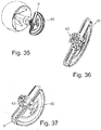
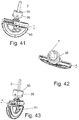
- FIGS. 35, 36, 37 . 41 the closing element 40 is shown. This is formed pivotable along a pivot axis V in its orientation. In the pivoting position shown here, the closing element 40 is opened, so that an air flow through the cylindrical portion of the air nozzle housing and out of the attachment element 18 can emerge (not shown).
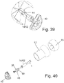
- the same open pivot position is in Fig. 39 shown.
- the joint head 22 in this case has two guide projections 44.
- this force is transmitted via the two movement-limiting guide projections 44 to the coupling element 38 and further to the closing element 40.
- Fig. 41 is the in Fig. 35 shown embodiment of an air nozzle 28 for the attachment element 18 and the closing element, wherein in FIGS. 42 and 43 the pivoting mechanism about the pivot axis V is shown.
- the actuating element 42 undergoes a force application and forwards it to sections of the closing element 40 which are designed to be complementary thereto. This pivots in the range of 0 to 90 °.
- the closing element 30 is also shown in the closed, ie air-flow-transmitting state, which is arranged on the insert element 52 via adjusting element 42 and coupling element 38. This is arranged on the latching lugs (not shown) on the coupling element 38.
- FIG. 39 the coupling between closing element 40 and attachment element 18 is shown.
- FIG. 41 - 43 are different views of the closing element 40 with arranged thereon actuator 42 and coupling element 38 is shown.
- a rotation about the longitudinal axis of the fastening element 2 which sets the actuator 42 in rotation, so that the advantageous double-sided closing element 40 to the Rotation axis rotates, gets up or in, as shown here, folded state remains.
- This movement is supported by the guide projections 44 of the condyle 22.
- FIG Fig. 40 shown A further exploded view of a further embodiment is shown in FIG Fig. 40 shown. This embodiment differs from that in FIG Fig. 34 shown embodiment in that an additional brake element 50 for adjusting the operating force of the attachment element 18 is disposed within the coupling element 38.
- the air nozzle is completely formed of plastic.
Landscapes
- Physics & Mathematics (AREA)
- Thermal Sciences (AREA)
- Engineering & Computer Science (AREA)
- Mechanical Engineering (AREA)
- Prostheses (AREA)
- Nozzles (AREA)
- Respiratory Apparatuses And Protective Means (AREA)
- Duct Arrangements (AREA)
- Jet Pumps And Other Pumps (AREA)
Claims (9)
- Buse à air (28) comprenant
au moins un boîtier de buse à air (12), qui est conçu pour le logement au moins partiel d'une portion de coussinet à rotule (1), le boîtier de buse à air (12) comprenant une portion en forme de manchon (14) pour le logement au moins partiel d'une portion de coussinet à rotule (1),
en outre au moins un élément rapporté (18) pour l'orientation d'un flux d'air sortant, qui comprend au moins une tête d'articulation (22),
en outre au moins une portion de coussinet à rotule (1) qui comprend, au niveau d'une première extrémité libre au moins un coussinet à rotule (4) pour le logement au moins partiel de la tête d'articulation (22), ainsi qu'une portion de prolongement (8) qui s'y raccorde, la portion de prolongement (8) étant conçue de façon à ce qu'elle puisse être disposée au moins partiellement dans la portion en forme de manchon (14) du boîtier de buse à air (12),
en outre un élément de fixation (34) pour la fixation de la portion de coussinet à rotule (1) dans la portion en forme de manchon (14),
la tête d'articulation (22) et le coussinet à rotule (4) étant conçus comme une liaison articulée,
la portion de prolongement (8) comprenant, au niveau de son extrémité libre opposée au coussinet à rotule (4), au moins un rétrécissement de matériau (30), caractérisé en ce que, au niveau de l'extrémité libre du rétrécissement de matériau (30) se trouve au moins une saillie (32) et
l'élément de fixation (34) peut être enfiché sur le rétrécissement de matériau (30) et sur l'au moins une saillie (32). - Buse à air selon la revendication 1,
caractérisée en ce que
la portion en forme de manchon (14) est réalisée avec une courbure conique et/ou convexe et/ou concave au niveau de son extrémité libre. - Buse à air selon la revendication 1,
caractérisée en ce que
le coussinet à rotule (4) est conçu de façon à ce que son diamètre puisse être modifié directement et/ou indirectement. - Buse à air selon la revendication 1,
caractérisée en ce que
le coussinet à rotule (4) comprend au moins une ouverture (6) s'étendant dans la direction longitudinale de la portion de coussinet à rotule (1). - Buse à air selon la revendication 1,
caractérisée en ce que
l'élément de fixation (34) est conçu comme un élément de tension. - Buse à air selon au moins l'une des revendications précédentes,
caractérisée en ce que
elle comprend en outre au moins un élément de fermeture (40) pour le contrôle du flux d'air sortant de la buse à air (28). - Buse à air selon la revendication 6,
caractérisée en ce que
l'élément de fermeture (40) est conçu de façon à être relié par l'intermédiaire d'au moins un élément de couplage (38) et/ou un élément de réglage (42) avec un insert (52) et/ou la portion en forme de manchon (14). - Buse à air selon la revendication 1,
caractérisée en ce que
la liaison articulée entre la tête d'articulation (22) et le coussinet à rotule (4) est conçue de façon à ce que l'élément rapporté (18) soit disposé et puisse tourner au moins partiellement à l'intérieur du boîtier de buse à air (12). - Utilisation d'une buse à air selon au moins l'une des revendications précédentes en tant que buse à air sphérique pour des installations de chauffage, de climatisation et/ou de ventilation à l'intérieur de véhicules.
Applications Claiming Priority (1)
| Application Number | Priority Date | Filing Date | Title |
|---|---|---|---|
| DE102015000256 | 2015-01-16 |
Publications (3)
| Publication Number | Publication Date |
|---|---|
| EP3045332A2 EP3045332A2 (fr) | 2016-07-20 |
| EP3045332A3 EP3045332A3 (fr) | 2017-01-11 |
| EP3045332B1 true EP3045332B1 (fr) | 2018-07-18 |
Family
ID=55024012
Family Applications (1)
| Application Number | Title | Priority Date | Filing Date |
|---|---|---|---|
| EP15202432.9A Active EP3045332B1 (fr) | 2015-01-16 | 2015-12-23 | Buse d'air |
Country Status (2)
| Country | Link |
|---|---|
| EP (1) | EP3045332B1 (fr) |
| ES (1) | ES2689445T3 (fr) |
Family Cites Families (5)
| Publication number | Priority date | Publication date | Assignee | Title |
|---|---|---|---|---|
| GB1310493A (en) * | 1969-01-11 | 1973-03-21 | Smiths Industries Ltd | Combined swivellable ventilating nozzle and flow control valve |
| GB1396993A (en) * | 1972-04-19 | 1975-06-11 | Clear Hooters Ltd | Ventilating nozzle including a universally swivellable nozzle member and a flow control valve |
| DE19701499C1 (de) * | 1997-01-17 | 1997-12-11 | Daimler Benz Ag | Belüftungsdüse für Fahrzeuge |
| FR2792256B1 (fr) * | 1999-04-16 | 2001-06-15 | 3 D Dev | Aerateur, notamment pour habitacle de vehicule automobile |
| DE102010032233B3 (de) * | 2010-07-26 | 2011-07-21 | TRW Automotive Electronics & Components GmbH, 78315 | Luftausströmer |
-
2015
- 2015-12-23 ES ES15202432.9T patent/ES2689445T3/es active Active
- 2015-12-23 EP EP15202432.9A patent/EP3045332B1/fr active Active
Non-Patent Citations (1)
| Title |
|---|
| None * |
Also Published As
| Publication number | Publication date |
|---|---|
| EP3045332A3 (fr) | 2017-01-11 |
| ES2689445T3 (es) | 2018-11-14 |
| EP3045332A2 (fr) | 2016-07-20 |
Similar Documents
| Publication | Publication Date | Title |
|---|---|---|
| DE102013101887B4 (de) | Einknopfbedienung für einen Luftausströmer | |
| EP1588877A1 (fr) | Buse d'aération | |
| DE19701499C1 (de) | Belüftungsdüse für Fahrzeuge | |
| EP2340178A1 (fr) | Buse d air | |
| WO2013107486A1 (fr) | Colonne de direction pour un véhicule automobile | |
| DE102009009241B4 (de) | In die Armaturentafel eines Kraftfahrzeuges einbaubarer Ausströmer | |
| DE102009041532A1 (de) | Dralleinrichtung für einen Luftausströmer | |
| DE202016002951U1 (de) | Luftausströmer zur Anordnung im Innenraum eines Kraftfahrzeugs | |
| DE102005059532B4 (de) | Gelenkstruktur eines Handschuhfachs für ein Fahrzeug | |
| DE202004013430U1 (de) | Luftdüse | |
| DE3626790C2 (fr) | ||
| DE10046721B4 (de) | Lüftungsdüse | |
| DE10223660B4 (de) | Luftausströmer für ein Fahrzeug, insbesondere für ein Kraftfahrzeug | |
| EP2161513A2 (fr) | Tuyère d'air | |
| WO2016188825A1 (fr) | Diffuseur d'air pour véhicule automobile | |
| DE102004013171B3 (de) | Luftdüse | |
| EP3606779B1 (fr) | Élément de guidage d'air comprenant un élément de friction et un diffuseur d'air | |
| DE102015219524B4 (de) | Ventilkartusche mit anschlagbegrenzt drehbeweglicher Ventilverstelleinrichtung | |
| EP3045332B1 (fr) | Buse d'air | |
| DE202010008054U1 (de) | Luftausströmer als Ausstattungsteil für Kraftfahrzeuge | |
| DE202009018491U1 (de) | Verschluss für eine Tür eines Gargeräts sowie Gargerät | |
| DE19653815C2 (de) | Betätigungshebel zur Betätigung eines Verstellhebels in einem Automobil | |
| EP1914432A2 (fr) | Dispositif de sécurité destiné à éviter des dommages sur un dispositif de transmission de couples | |
| EP1854951A2 (fr) | Fermeture de véhicule automobile | |
| EP2371254A2 (fr) | Articulation |
Legal Events
| Date | Code | Title | Description |
|---|---|---|---|
| PUAI | Public reference made under article 153(3) epc to a published international application that has entered the european phase |
Free format text: ORIGINAL CODE: 0009012 |
|
| AK | Designated contracting states |
Kind code of ref document: A2 Designated state(s): AL AT BE BG CH CY CZ DE DK EE ES FI FR GB GR HR HU IE IS IT LI LT LU LV MC MK MT NL NO PL PT RO RS SE SI SK SM TR |
|
| AX | Request for extension of the european patent |
Extension state: BA ME |
|
| PUAL | Search report despatched |
Free format text: ORIGINAL CODE: 0009013 |
|
| AK | Designated contracting states |
Kind code of ref document: A3 Designated state(s): AL AT BE BG CH CY CZ DE DK EE ES FI FR GB GR HR HU IE IS IT LI LT LU LV MC MK MT NL NO PL PT RO RS SE SI SK SM TR |
|
| AX | Request for extension of the european patent |
Extension state: BA ME |
|
| RIC1 | Information provided on ipc code assigned before grant |
Ipc: B64D 13/00 20060101ALI20161206BHEP Ipc: B60H 1/34 20060101AFI20161206BHEP |
|
| 17P | Request for examination filed |
Effective date: 20170711 |
|
| RBV | Designated contracting states (corrected) |
Designated state(s): AL AT BE BG CH CY CZ DE DK EE ES FI FR GB GR HR HU IE IS IT LI LT LU LV MC MK MT NL NO PL PT RO RS SE SI SK SM TR |
|
| 17Q | First examination report despatched |
Effective date: 20170921 |
|
| GRAP | Despatch of communication of intention to grant a patent |
Free format text: ORIGINAL CODE: EPIDOSNIGR1 |
|
| INTG | Intention to grant announced |
Effective date: 20180308 |
|
| GRAS | Grant fee paid |
Free format text: ORIGINAL CODE: EPIDOSNIGR3 |
|
| GRAA | (expected) grant |
Free format text: ORIGINAL CODE: 0009210 |
|
| AK | Designated contracting states |
Kind code of ref document: B1 Designated state(s): AL AT BE BG CH CY CZ DE DK EE ES FI FR GB GR HR HU IE IS IT LI LT LU LV MC MK MT NL NO PL PT RO RS SE SI SK SM TR |
|
| REG | Reference to a national code |
Ref country code: GB Ref legal event code: FG4D Free format text: NOT ENGLISH |
|
| REG | Reference to a national code |
Ref country code: CH Ref legal event code: EP |
|
| REG | Reference to a national code |
Ref country code: IE Ref legal event code: FG4D Free format text: LANGUAGE OF EP DOCUMENT: GERMAN |
|
| REG | Reference to a national code |
Ref country code: AT Ref legal event code: REF Ref document number: 1018958 Country of ref document: AT Kind code of ref document: T Effective date: 20180815 |
|
| REG | Reference to a national code |
Ref country code: DE Ref legal event code: R096 Ref document number: 502015005117 Country of ref document: DE |
|
| REG | Reference to a national code |
Ref country code: SE Ref legal event code: TRGR |
|
| REG | Reference to a national code |
Ref country code: ES Ref legal event code: FG2A Ref document number: 2689445 Country of ref document: ES Kind code of ref document: T3 Effective date: 20181114 |
|
| REG | Reference to a national code |
Ref country code: NL Ref legal event code: MP Effective date: 20180718 |
|
| REG | Reference to a national code |
Ref country code: LT Ref legal event code: MG4D |
|
| PG25 | Lapsed in a contracting state [announced via postgrant information from national office to epo] |
Ref country code: NL Free format text: LAPSE BECAUSE OF FAILURE TO SUBMIT A TRANSLATION OF THE DESCRIPTION OR TO PAY THE FEE WITHIN THE PRESCRIBED TIME-LIMIT Effective date: 20180718 |
|
| PG25 | Lapsed in a contracting state [announced via postgrant information from national office to epo] |
Ref country code: FI Free format text: LAPSE BECAUSE OF FAILURE TO SUBMIT A TRANSLATION OF THE DESCRIPTION OR TO PAY THE FEE WITHIN THE PRESCRIBED TIME-LIMIT Effective date: 20180718 Ref country code: PL Free format text: LAPSE BECAUSE OF FAILURE TO SUBMIT A TRANSLATION OF THE DESCRIPTION OR TO PAY THE FEE WITHIN THE PRESCRIBED TIME-LIMIT Effective date: 20180718 Ref country code: LT Free format text: LAPSE BECAUSE OF FAILURE TO SUBMIT A TRANSLATION OF THE DESCRIPTION OR TO PAY THE FEE WITHIN THE PRESCRIBED TIME-LIMIT Effective date: 20180718 Ref country code: RS Free format text: LAPSE BECAUSE OF FAILURE TO SUBMIT A TRANSLATION OF THE DESCRIPTION OR TO PAY THE FEE WITHIN THE PRESCRIBED TIME-LIMIT Effective date: 20180718 Ref country code: BG Free format text: LAPSE BECAUSE OF FAILURE TO SUBMIT A TRANSLATION OF THE DESCRIPTION OR TO PAY THE FEE WITHIN THE PRESCRIBED TIME-LIMIT Effective date: 20181018 Ref country code: IS Free format text: LAPSE BECAUSE OF FAILURE TO SUBMIT A TRANSLATION OF THE DESCRIPTION OR TO PAY THE FEE WITHIN THE PRESCRIBED TIME-LIMIT Effective date: 20181118 Ref country code: NO Free format text: LAPSE BECAUSE OF FAILURE TO SUBMIT A TRANSLATION OF THE DESCRIPTION OR TO PAY THE FEE WITHIN THE PRESCRIBED TIME-LIMIT Effective date: 20181018 Ref country code: GR Free format text: LAPSE BECAUSE OF FAILURE TO SUBMIT A TRANSLATION OF THE DESCRIPTION OR TO PAY THE FEE WITHIN THE PRESCRIBED TIME-LIMIT Effective date: 20181019 |
|
| PG25 | Lapsed in a contracting state [announced via postgrant information from national office to epo] |
Ref country code: AL Free format text: LAPSE BECAUSE OF FAILURE TO SUBMIT A TRANSLATION OF THE DESCRIPTION OR TO PAY THE FEE WITHIN THE PRESCRIBED TIME-LIMIT Effective date: 20180718 Ref country code: LV Free format text: LAPSE BECAUSE OF FAILURE TO SUBMIT A TRANSLATION OF THE DESCRIPTION OR TO PAY THE FEE WITHIN THE PRESCRIBED TIME-LIMIT Effective date: 20180718 Ref country code: HR Free format text: LAPSE BECAUSE OF FAILURE TO SUBMIT A TRANSLATION OF THE DESCRIPTION OR TO PAY THE FEE WITHIN THE PRESCRIBED TIME-LIMIT Effective date: 20180718 |
|
| REG | Reference to a national code |
Ref country code: DE Ref legal event code: R097 Ref document number: 502015005117 Country of ref document: DE |
|
| PG25 | Lapsed in a contracting state [announced via postgrant information from national office to epo] |
Ref country code: EE Free format text: LAPSE BECAUSE OF FAILURE TO SUBMIT A TRANSLATION OF THE DESCRIPTION OR TO PAY THE FEE WITHIN THE PRESCRIBED TIME-LIMIT Effective date: 20180718 Ref country code: CZ Free format text: LAPSE BECAUSE OF FAILURE TO SUBMIT A TRANSLATION OF THE DESCRIPTION OR TO PAY THE FEE WITHIN THE PRESCRIBED TIME-LIMIT Effective date: 20180718 Ref country code: RO Free format text: LAPSE BECAUSE OF FAILURE TO SUBMIT A TRANSLATION OF THE DESCRIPTION OR TO PAY THE FEE WITHIN THE PRESCRIBED TIME-LIMIT Effective date: 20180718 |
|
| PLBE | No opposition filed within time limit |
Free format text: ORIGINAL CODE: 0009261 |
|
| STAA | Information on the status of an ep patent application or granted ep patent |
Free format text: STATUS: NO OPPOSITION FILED WITHIN TIME LIMIT |
|
| PG25 | Lapsed in a contracting state [announced via postgrant information from national office to epo] |
Ref country code: DK Free format text: LAPSE BECAUSE OF FAILURE TO SUBMIT A TRANSLATION OF THE DESCRIPTION OR TO PAY THE FEE WITHIN THE PRESCRIBED TIME-LIMIT Effective date: 20180718 Ref country code: SM Free format text: LAPSE BECAUSE OF FAILURE TO SUBMIT A TRANSLATION OF THE DESCRIPTION OR TO PAY THE FEE WITHIN THE PRESCRIBED TIME-LIMIT Effective date: 20180718 Ref country code: SK Free format text: LAPSE BECAUSE OF FAILURE TO SUBMIT A TRANSLATION OF THE DESCRIPTION OR TO PAY THE FEE WITHIN THE PRESCRIBED TIME-LIMIT Effective date: 20180718 |
|
| 26N | No opposition filed |
Effective date: 20190423 |
|
| REG | Reference to a national code |
Ref country code: CH Ref legal event code: PL |
|
| PG25 | Lapsed in a contracting state [announced via postgrant information from national office to epo] |
Ref country code: MC Free format text: LAPSE BECAUSE OF FAILURE TO SUBMIT A TRANSLATION OF THE DESCRIPTION OR TO PAY THE FEE WITHIN THE PRESCRIBED TIME-LIMIT Effective date: 20180718 Ref country code: LU Free format text: LAPSE BECAUSE OF NON-PAYMENT OF DUE FEES Effective date: 20181223 Ref country code: SI Free format text: LAPSE BECAUSE OF FAILURE TO SUBMIT A TRANSLATION OF THE DESCRIPTION OR TO PAY THE FEE WITHIN THE PRESCRIBED TIME-LIMIT Effective date: 20180718 |
|
| REG | Reference to a national code |
Ref country code: IE Ref legal event code: MM4A |
|
| REG | Reference to a national code |
Ref country code: BE Ref legal event code: MM Effective date: 20181231 |
|
| PG25 | Lapsed in a contracting state [announced via postgrant information from national office to epo] |
Ref country code: IE Free format text: LAPSE BECAUSE OF NON-PAYMENT OF DUE FEES Effective date: 20181223 |
|
| PG25 | Lapsed in a contracting state [announced via postgrant information from national office to epo] |
Ref country code: BE Free format text: LAPSE BECAUSE OF NON-PAYMENT OF DUE FEES Effective date: 20181231 |
|
| PG25 | Lapsed in a contracting state [announced via postgrant information from national office to epo] |
Ref country code: LI Free format text: LAPSE BECAUSE OF NON-PAYMENT OF DUE FEES Effective date: 20181231 Ref country code: CH Free format text: LAPSE BECAUSE OF NON-PAYMENT OF DUE FEES Effective date: 20181231 |
|
| PG25 | Lapsed in a contracting state [announced via postgrant information from national office to epo] |
Ref country code: MT Free format text: LAPSE BECAUSE OF FAILURE TO SUBMIT A TRANSLATION OF THE DESCRIPTION OR TO PAY THE FEE WITHIN THE PRESCRIBED TIME-LIMIT Effective date: 20180718 |
|
| PG25 | Lapsed in a contracting state [announced via postgrant information from national office to epo] |
Ref country code: TR Free format text: LAPSE BECAUSE OF FAILURE TO SUBMIT A TRANSLATION OF THE DESCRIPTION OR TO PAY THE FEE WITHIN THE PRESCRIBED TIME-LIMIT Effective date: 20180718 |
|
| PG25 | Lapsed in a contracting state [announced via postgrant information from national office to epo] |
Ref country code: PT Free format text: LAPSE BECAUSE OF FAILURE TO SUBMIT A TRANSLATION OF THE DESCRIPTION OR TO PAY THE FEE WITHIN THE PRESCRIBED TIME-LIMIT Effective date: 20180718 |
|
| PG25 | Lapsed in a contracting state [announced via postgrant information from national office to epo] |
Ref country code: CY Free format text: LAPSE BECAUSE OF FAILURE TO SUBMIT A TRANSLATION OF THE DESCRIPTION OR TO PAY THE FEE WITHIN THE PRESCRIBED TIME-LIMIT Effective date: 20180718 Ref country code: MK Free format text: LAPSE BECAUSE OF NON-PAYMENT OF DUE FEES Effective date: 20180718 Ref country code: HU Free format text: LAPSE BECAUSE OF FAILURE TO SUBMIT A TRANSLATION OF THE DESCRIPTION OR TO PAY THE FEE WITHIN THE PRESCRIBED TIME-LIMIT; INVALID AB INITIO Effective date: 20151223 |
|
| REG | Reference to a national code |
Ref country code: AT Ref legal event code: MM01 Ref document number: 1018958 Country of ref document: AT Kind code of ref document: T Effective date: 20201223 |
|
| PG25 | Lapsed in a contracting state [announced via postgrant information from national office to epo] |
Ref country code: AT Free format text: LAPSE BECAUSE OF NON-PAYMENT OF DUE FEES Effective date: 20201223 |
|
| P01 | Opt-out of the competence of the unified patent court (upc) registered |
Effective date: 20230525 |
|
| PGFP | Annual fee paid to national office [announced via postgrant information from national office to epo] |
Ref country code: SE Payment date: 20241221 Year of fee payment: 10 |
|
| REG | Reference to a national code |
Ref country code: DE Ref legal event code: R081 Ref document number: 502015005117 Country of ref document: DE Owner name: MOTHERSON DRSC DEUTSCHLAND GMBH, DE Free format text: FORMER OWNER: DR. SCHNEIDER KUNSTSTOFFWERKE GMBH, 96317 KRONACH, DE |
|
| REG | Reference to a national code |
Ref country code: GB Ref legal event code: 732E Free format text: REGISTERED BETWEEN 20250724 AND 20250730 |
|
| PGFP | Annual fee paid to national office [announced via postgrant information from national office to epo] |
Ref country code: GB Payment date: 20251218 Year of fee payment: 11 |
|
| PGFP | Annual fee paid to national office [announced via postgrant information from national office to epo] |
Ref country code: FR Payment date: 20251218 Year of fee payment: 11 |
|
| PGFP | Annual fee paid to national office [announced via postgrant information from national office to epo] |
Ref country code: ES Payment date: 20260119 Year of fee payment: 11 |
|
| PGFP | Annual fee paid to national office [announced via postgrant information from national office to epo] |
Ref country code: DE Payment date: 20251222 Year of fee payment: 11 |
|
| PGFP | Annual fee paid to national office [announced via postgrant information from national office to epo] |
Ref country code: IT Payment date: 20251231 Year of fee payment: 11 |