EP3045575A1 - Verfahren zur herstellung von graphitnanofasern aus biogas - Google Patents
Verfahren zur herstellung von graphitnanofasern aus biogas Download PDFInfo
- Publication number
- EP3045575A1 EP3045575A1 EP14822242.5A EP14822242A EP3045575A1 EP 3045575 A1 EP3045575 A1 EP 3045575A1 EP 14822242 A EP14822242 A EP 14822242A EP 3045575 A1 EP3045575 A1 EP 3045575A1
- Authority
- EP
- European Patent Office
- Prior art keywords
- process according
- biogas
- ranging
- final temperature
- carbon
- Prior art date
- Legal status (The legal status is an assumption and is not a legal conclusion. Google has not performed a legal analysis and makes no representation as to the accuracy of the status listed.)
- Withdrawn
Links
- OKTJSMMVPCPJKN-UHFFFAOYSA-N Carbon Chemical compound [C] OKTJSMMVPCPJKN-UHFFFAOYSA-N 0.000 title claims abstract description 60
- 238000000034 method Methods 0.000 title claims abstract description 34
- 229910002804 graphite Inorganic materials 0.000 title claims description 33
- 239000010439 graphite Substances 0.000 title claims description 33
- 229910052799 carbon Inorganic materials 0.000 claims abstract description 25
- 238000004519 manufacturing process Methods 0.000 claims abstract description 17
- 239000000463 material Substances 0.000 claims abstract description 13
- UFHFLCQGNIYNRP-UHFFFAOYSA-N Hydrogen Chemical compound [H][H] UFHFLCQGNIYNRP-UHFFFAOYSA-N 0.000 claims abstract description 9
- 229910052739 hydrogen Inorganic materials 0.000 claims abstract description 9
- 239000001257 hydrogen Substances 0.000 claims abstract description 9
- 239000012298 atmosphere Substances 0.000 claims abstract description 6
- 229910052751 metal Inorganic materials 0.000 claims abstract description 6
- 239000002184 metal Substances 0.000 claims abstract description 6
- 239000007789 gas Substances 0.000 claims abstract description 5
- 230000003197 catalytic effect Effects 0.000 claims abstract description 4
- VNWKTOKETHGBQD-UHFFFAOYSA-N methane Chemical compound C VNWKTOKETHGBQD-UHFFFAOYSA-N 0.000 claims description 28
- 238000010438 heat treatment Methods 0.000 claims description 23
- CURLTUGMZLYLDI-UHFFFAOYSA-N Carbon dioxide Chemical compound O=C=O CURLTUGMZLYLDI-UHFFFAOYSA-N 0.000 claims description 18
- VYPSYNLAJGMNEJ-UHFFFAOYSA-N Silicium dioxide Chemical compound O=[Si]=O VYPSYNLAJGMNEJ-UHFFFAOYSA-N 0.000 claims description 16
- 238000003421 catalytic decomposition reaction Methods 0.000 claims description 15
- 239000003054 catalyst Substances 0.000 claims description 14
- 229910002092 carbon dioxide Inorganic materials 0.000 claims description 13
- HBBGRARXTFLTSG-UHFFFAOYSA-N Lithium ion Chemical compound [Li+] HBBGRARXTFLTSG-UHFFFAOYSA-N 0.000 claims description 11
- 229910001416 lithium ion Inorganic materials 0.000 claims description 11
- PNEYBMLMFCGWSK-UHFFFAOYSA-N aluminium oxide Inorganic materials [O-2].[O-2].[O-2].[Al+3].[Al+3] PNEYBMLMFCGWSK-UHFFFAOYSA-N 0.000 claims description 8
- 239000000203 mixture Substances 0.000 claims description 8
- 239000000377 silicon dioxide Substances 0.000 claims description 8
- 229910052593 corundum Inorganic materials 0.000 claims description 7
- 229910052759 nickel Inorganic materials 0.000 claims description 7
- 229910001845 yogo sapphire Inorganic materials 0.000 claims description 7
- GWEVSGVZZGPLCZ-UHFFFAOYSA-N Titan oxide Chemical compound O=[Ti]=O GWEVSGVZZGPLCZ-UHFFFAOYSA-N 0.000 claims description 6
- 239000011149 active material Substances 0.000 claims description 6
- CPLXHLVBOLITMK-UHFFFAOYSA-N Magnesium oxide Chemical compound [Mg]=O CPLXHLVBOLITMK-UHFFFAOYSA-N 0.000 claims description 5
- 239000001569 carbon dioxide Substances 0.000 claims description 5
- 229910052802 copper Inorganic materials 0.000 claims description 4
- 239000013081 microcrystal Substances 0.000 claims description 4
- 239000000843 powder Substances 0.000 claims description 4
- 229910052681 coesite Inorganic materials 0.000 claims description 3
- 229910052906 cristobalite Inorganic materials 0.000 claims description 3
- 238000000354 decomposition reaction Methods 0.000 claims description 3
- 239000008240 homogeneous mixture Substances 0.000 claims description 3
- 229910052742 iron Inorganic materials 0.000 claims description 3
- 238000010907 mechanical stirring Methods 0.000 claims description 3
- 238000007500 overflow downdraw method Methods 0.000 claims description 3
- 229910052710 silicon Inorganic materials 0.000 claims description 3
- 229910052682 stishovite Inorganic materials 0.000 claims description 3
- 229910052905 tridymite Inorganic materials 0.000 claims description 3
- 239000011261 inert gas Substances 0.000 claims description 2
- 229910052750 molybdenum Inorganic materials 0.000 claims description 2
- 229910052763 palladium Inorganic materials 0.000 claims description 2
- 238000005979 thermal decomposition reaction Methods 0.000 claims description 2
- 239000003575 carbonaceous material Substances 0.000 abstract description 5
- 229910021383 artificial graphite Inorganic materials 0.000 abstract description 3
- 229910052744 lithium Inorganic materials 0.000 abstract description 2
- 230000015556 catabolic process Effects 0.000 abstract 1
- 238000011084 recovery Methods 0.000 abstract 1
- 238000007669 thermal treatment Methods 0.000 abstract 1
- PXHVJJICTQNCMI-UHFFFAOYSA-N nickel Substances [Ni] PXHVJJICTQNCMI-UHFFFAOYSA-N 0.000 description 19
- 239000013078 crystal Substances 0.000 description 7
- 210000004027 cell Anatomy 0.000 description 5
- 238000002441 X-ray diffraction Methods 0.000 description 4
- 239000010949 copper Substances 0.000 description 4
- 239000002121 nanofiber Substances 0.000 description 4
- 239000002033 PVDF binder Substances 0.000 description 3
- 229910052782 aluminium Inorganic materials 0.000 description 3
- 230000001351 cycling effect Effects 0.000 description 3
- 238000002474 experimental method Methods 0.000 description 3
- 229920002981 polyvinylidene fluoride Polymers 0.000 description 3
- 238000011282 treatment Methods 0.000 description 3
- XKRFYHLGVUSROY-UHFFFAOYSA-N Argon Chemical compound [Ar] XKRFYHLGVUSROY-UHFFFAOYSA-N 0.000 description 2
- IJGRMHOSHXDMSA-UHFFFAOYSA-N Atomic nitrogen Chemical compound N#N IJGRMHOSHXDMSA-UHFFFAOYSA-N 0.000 description 2
- RYGMFSIKBFXOCR-UHFFFAOYSA-N Copper Chemical compound [Cu] RYGMFSIKBFXOCR-UHFFFAOYSA-N 0.000 description 2
- OIFBSDVPJOWBCH-UHFFFAOYSA-N Diethyl carbonate Chemical compound CCOC(=O)OCC OIFBSDVPJOWBCH-UHFFFAOYSA-N 0.000 description 2
- KMTRUDSVKNLOMY-UHFFFAOYSA-N Ethylene carbonate Chemical compound O=C1OCCO1 KMTRUDSVKNLOMY-UHFFFAOYSA-N 0.000 description 2
- 239000004411 aluminium Substances 0.000 description 2
- XAGFODPZIPBFFR-UHFFFAOYSA-N aluminium Chemical compound [Al] XAGFODPZIPBFFR-UHFFFAOYSA-N 0.000 description 2
- 230000015572 biosynthetic process Effects 0.000 description 2
- 238000011161 development Methods 0.000 description 2
- 238000009792 diffusion process Methods 0.000 description 2
- 239000003792 electrolyte Substances 0.000 description 2
- 238000000921 elemental analysis Methods 0.000 description 2
- 239000000446 fuel Substances 0.000 description 2
- 230000014759 maintenance of location Effects 0.000 description 2
- 238000005259 measurement Methods 0.000 description 2
- SZNYUUZOQHNEKB-UHFFFAOYSA-N n-[4-methyl-3-[1-methyl-7-[(6-methylpyridin-3-yl)amino]-2-oxo-4h-pyrimido[4,5-d]pyrimidin-3-yl]phenyl]-3-(trifluoromethyl)benzamide Chemical compound N1=C2N(C)C(=O)N(C=3C(=CC=C(NC(=O)C=4C=C(C=CC=4)C(F)(F)F)C=3)C)CC2=CN=C1NC1=CC=C(C)N=C1 SZNYUUZOQHNEKB-UHFFFAOYSA-N 0.000 description 2
- 239000003209 petroleum derivative Substances 0.000 description 2
- 238000002360 preparation method Methods 0.000 description 2
- 238000000746 purification Methods 0.000 description 2
- 238000001878 scanning electron micrograph Methods 0.000 description 2
- 239000007858 starting material Substances 0.000 description 2
- 239000000725 suspension Substances 0.000 description 2
- 229910001290 LiPF6 Inorganic materials 0.000 description 1
- WHXSMMKQMYFTQS-UHFFFAOYSA-N Lithium Chemical compound [Li] WHXSMMKQMYFTQS-UHFFFAOYSA-N 0.000 description 1
- SECXISVLQFMRJM-UHFFFAOYSA-N N-Methylpyrrolidone Chemical compound CN1CCCC1=O SECXISVLQFMRJM-UHFFFAOYSA-N 0.000 description 1
- 229910000831 Steel Inorganic materials 0.000 description 1
- 239000004809 Teflon Substances 0.000 description 1
- 229920006362 Teflon® Polymers 0.000 description 1
- 238000004458 analytical method Methods 0.000 description 1
- 238000004873 anchoring Methods 0.000 description 1
- 229910052786 argon Inorganic materials 0.000 description 1
- 125000003118 aryl group Chemical group 0.000 description 1
- QVGXLLKOCUKJST-UHFFFAOYSA-N atomic oxygen Chemical compound [O] QVGXLLKOCUKJST-UHFFFAOYSA-N 0.000 description 1
- 239000011230 binding agent Substances 0.000 description 1
- 238000004364 calculation method Methods 0.000 description 1
- 238000006555 catalytic reaction Methods 0.000 description 1
- 210000003850 cellular structure Anatomy 0.000 description 1
- 238000005229 chemical vapour deposition Methods 0.000 description 1
- 239000002131 composite material Substances 0.000 description 1
- 230000007423 decrease Effects 0.000 description 1
- 238000001514 detection method Methods 0.000 description 1
- 238000001493 electron microscopy Methods 0.000 description 1
- 238000004146 energy storage Methods 0.000 description 1
- 238000011156 evaluation Methods 0.000 description 1
- 239000000835 fiber Substances 0.000 description 1
- 239000002803 fossil fuel Substances 0.000 description 1
- 239000011521 glass Substances 0.000 description 1
- 239000003365 glass fiber Substances 0.000 description 1
- 229910021389 graphene Inorganic materials 0.000 description 1
- 239000007770 graphite material Substances 0.000 description 1
- 229930195733 hydrocarbon Natural products 0.000 description 1
- 150000002430 hydrocarbons Chemical class 0.000 description 1
- 238000002065 inelastic X-ray scattering Methods 0.000 description 1
- 229910052749 magnesium Inorganic materials 0.000 description 1
- 238000004949 mass spectrometry Methods 0.000 description 1
- 239000002923 metal particle Substances 0.000 description 1
- 239000002086 nanomaterial Substances 0.000 description 1
- 239000003345 natural gas Substances 0.000 description 1
- 229910052757 nitrogen Inorganic materials 0.000 description 1
- 230000003287 optical effect Effects 0.000 description 1
- 239000003960 organic solvent Substances 0.000 description 1
- 230000003647 oxidation Effects 0.000 description 1
- 238000007254 oxidation reaction Methods 0.000 description 1
- 239000001301 oxygen Substances 0.000 description 1
- 229910052760 oxygen Inorganic materials 0.000 description 1
- 229920000642 polymer Polymers 0.000 description 1
- 230000008092 positive effect Effects 0.000 description 1
- 239000002243 precursor Substances 0.000 description 1
- 230000005855 radiation Effects 0.000 description 1
- 239000013558 reference substance Substances 0.000 description 1
- 238000005057 refrigeration Methods 0.000 description 1
- 238000011160 research Methods 0.000 description 1
- 239000002904 solvent Substances 0.000 description 1
- 229910001220 stainless steel Inorganic materials 0.000 description 1
- 239000010935 stainless steel Substances 0.000 description 1
- 239000010959 steel Substances 0.000 description 1
- 238000003786 synthesis reaction Methods 0.000 description 1
- 229910052719 titanium Inorganic materials 0.000 description 1
- 229910052723 transition metal Inorganic materials 0.000 description 1
- 150000003624 transition metals Chemical class 0.000 description 1
- 238000004627 transmission electron microscopy Methods 0.000 description 1
Images


Classifications
-
- D—TEXTILES; PAPER
- D01—NATURAL OR MAN-MADE THREADS OR FIBRES; SPINNING
- D01F—CHEMICAL FEATURES IN THE MANUFACTURE OF ARTIFICIAL FILAMENTS, THREADS, FIBRES, BRISTLES OR RIBBONS; APPARATUS SPECIALLY ADAPTED FOR THE MANUFACTURE OF CARBON FILAMENTS
- D01F9/00—Artificial filaments or the like of other substances; Manufacture thereof; Apparatus specially adapted for the manufacture of carbon filaments
- D01F9/08—Artificial filaments or the like of other substances; Manufacture thereof; Apparatus specially adapted for the manufacture of carbon filaments of inorganic material
- D01F9/12—Carbon filaments; Apparatus specially adapted for the manufacture thereof
- D01F9/127—Carbon filaments; Apparatus specially adapted for the manufacture thereof by thermal decomposition of hydrocarbon gases or vapours or other carbon-containing compounds in the form of gas or vapour, e.g. carbon monoxide, alcohols
- D01F9/1271—Alkanes or cycloalkanes
- D01F9/1272—Methane
-
- B—PERFORMING OPERATIONS; TRANSPORTING
- B82—NANOTECHNOLOGY
- B82Y—SPECIFIC USES OR APPLICATIONS OF NANOSTRUCTURES; MEASUREMENT OR ANALYSIS OF NANOSTRUCTURES; MANUFACTURE OR TREATMENT OF NANOSTRUCTURES
- B82Y30/00—Nanotechnology for materials or surface science, e.g. nanocomposites
-
- C—CHEMISTRY; METALLURGY
- C01—INORGANIC CHEMISTRY
- C01B—NON-METALLIC ELEMENTS; COMPOUNDS THEREOF; METALLOIDS OR COMPOUNDS THEREOF NOT COVERED BY SUBCLASS C01C
- C01B32/00—Carbon; Compounds thereof
- C01B32/15—Nano-sized carbon materials
-
- D—TEXTILES; PAPER
- D01—NATURAL OR MAN-MADE THREADS OR FIBRES; SPINNING
- D01F—CHEMICAL FEATURES IN THE MANUFACTURE OF ARTIFICIAL FILAMENTS, THREADS, FIBRES, BRISTLES OR RIBBONS; APPARATUS SPECIALLY ADAPTED FOR THE MANUFACTURE OF CARBON FILAMENTS
- D01F9/00—Artificial filaments or the like of other substances; Manufacture thereof; Apparatus specially adapted for the manufacture of carbon filaments
- D01F9/08—Artificial filaments or the like of other substances; Manufacture thereof; Apparatus specially adapted for the manufacture of carbon filaments of inorganic material
- D01F9/12—Carbon filaments; Apparatus specially adapted for the manufacture thereof
- D01F9/127—Carbon filaments; Apparatus specially adapted for the manufacture thereof by thermal decomposition of hydrocarbon gases or vapours or other carbon-containing compounds in the form of gas or vapour, e.g. carbon monoxide, alcohols
-
- H—ELECTRICITY
- H01—ELECTRIC ELEMENTS
- H01M—PROCESSES OR MEANS, e.g. BATTERIES, FOR THE DIRECT CONVERSION OF CHEMICAL ENERGY INTO ELECTRICAL ENERGY
- H01M4/00—Electrodes
- H01M4/02—Electrodes composed of, or comprising, active material
- H01M4/13—Electrodes for accumulators with non-aqueous electrolyte, e.g. for lithium-accumulators; Processes of manufacture thereof
- H01M4/133—Electrodes based on carbonaceous material, e.g. graphite-intercalation compounds or CFx
-
- H—ELECTRICITY
- H01—ELECTRIC ELEMENTS
- H01M—PROCESSES OR MEANS, e.g. BATTERIES, FOR THE DIRECT CONVERSION OF CHEMICAL ENERGY INTO ELECTRICAL ENERGY
- H01M4/00—Electrodes
- H01M4/02—Electrodes composed of, or comprising, active material
- H01M4/36—Selection of substances as active materials, active masses, active liquids
- H01M4/58—Selection of substances as active materials, active masses, active liquids of inorganic compounds other than oxides or hydroxides, e.g. sulfides, selenides, tellurides, halogenides or LiCoFy; of polyanionic structures, e.g. phosphates, silicates or borates
- H01M4/583—Carbonaceous material, e.g. graphite-intercalation compounds or CFx
- H01M4/587—Carbonaceous material, e.g. graphite-intercalation compounds or CFx for inserting or intercalating light metals
-
- B—PERFORMING OPERATIONS; TRANSPORTING
- B82—NANOTECHNOLOGY
- B82Y—SPECIFIC USES OR APPLICATIONS OF NANOSTRUCTURES; MEASUREMENT OR ANALYSIS OF NANOSTRUCTURES; MANUFACTURE OR TREATMENT OF NANOSTRUCTURES
- B82Y40/00—Manufacture or treatment of nanostructures
-
- H—ELECTRICITY
- H01—ELECTRIC ELEMENTS
- H01M—PROCESSES OR MEANS, e.g. BATTERIES, FOR THE DIRECT CONVERSION OF CHEMICAL ENERGY INTO ELECTRICAL ENERGY
- H01M10/00—Secondary cells; Manufacture thereof
- H01M10/05—Accumulators with non-aqueous electrolyte
- H01M10/052—Li-accumulators
- H01M10/0525—Rocking-chair batteries, i.e. batteries with lithium insertion or intercalation in both electrodes; Lithium-ion batteries
-
- Y—GENERAL TAGGING OF NEW TECHNOLOGICAL DEVELOPMENTS; GENERAL TAGGING OF CROSS-SECTIONAL TECHNOLOGIES SPANNING OVER SEVERAL SECTIONS OF THE IPC; TECHNICAL SUBJECTS COVERED BY FORMER USPC CROSS-REFERENCE ART COLLECTIONS [XRACs] AND DIGESTS
- Y02—TECHNOLOGIES OR APPLICATIONS FOR MITIGATION OR ADAPTATION AGAINST CLIMATE CHANGE
- Y02E—REDUCTION OF GREENHOUSE GAS [GHG] EMISSIONS, RELATED TO ENERGY GENERATION, TRANSMISSION OR DISTRIBUTION
- Y02E60/00—Enabling technologies; Technologies with a potential or indirect contribution to GHG emissions mitigation
- Y02E60/10—Energy storage using batteries
Definitions
- the process of the present invention pertains to the sector devoted to the development of new materials and the applications thereof.
- An object of the present invention is a process for preparing graphite nanofibres, which comprises a step for performing the catalytic decomposition of a biogas composed of methane and carbon dioxide at a temperature ranging between 500oC and 800oC, to obtain carbon bio-nanofilaments; subsequently, the carbon bio-nanofilaments are subjected to heat treatment under an inert atmosphere, following a heating programme, to a final temperature ranging between 2400oC and 3000oC, to obtain the graphite nanofibres.
- Carbon nanofibres have diameters of ⁇ 100 nm and are formed by graphene sheets stacked in different ways: perpendicular, parallel or inclined with respect to the fibre axis, depending on the preparation method and the conditions.
- the production of CNFs by chemical vapour deposition, using CO and different hydrocarbons, over transition-metal catalysts, such as Fe, Co or Ni, has been widely studied, even from the standpoint of large-scale commercialisation, since, in the 1970s ( S. D. Robertson, Carbon 8, 365-368, 1970 ), the formation of carbon materials with different structures was observed on the surface of the catalyst during the catalytic decomposition of methane (CDM).
- CNFs obtained from the CDM have relatively high thermal and electrical conductivities as compared to other carbon materials. These properties, jointly with their nanometric size and their mesoporous character, make them suitable materials for various applications.
- various post-production treatments of the CNFs are necessary in order to optimise their properties with a view to their subsequent use, including high-temperature heat treatment (> 2000oC), which improves the graphite-type three-dimensional structural arrangement and the electrical conductivity, and reduces the active centres on the surface, to obtain, in some cases, materials similar to the synthetic graphite from petroleum derivatives produced in industry ( A. Ramos et al., Carbon 59, 2-32, 2013 ).
- the graphitisation of the CNFs produced by the CDM in a fluidised-bed reactor, using Cu-doped Ni catalysts supported on SiO 2 , Al 2 O 3 , TiO 2 or MgO, has been studied by Garc ⁇ a et al. (Carbon 47, 2563-79, 2009 ) and Caméan et al. (Carbon 50, 5387-94, 2012 ).
- the CNFs were treated in a graphite electric furnace within the temperature range 1800-2800oC for 1 h under a flow of argon.
- the materials prepared from the CNFs were characterised, amongst other techniques, by means of X-Ray Diffraction (XRD), Raman Spectroscopy and Transmission Electron Microscopy (TEM).
- the main object of this invention is to produce synthetic nanometric-size graphite fibres (graphite nanofibres, GNFs) with suitable properties in terms of structure, texture and electrical conductivity, to be used as anodes for lithium-ion batteries and/or other energy storage devices, starting from the CBNFs and using a heat treatment at temperatures greater than 2000oC.
- GNFs graphite nanofibres
- the main novelty of this process lies in the use of biogas as the starting material, without the need for a purification step to remove the CO 2 , and, in fact, this is the main difference with respect to Tada et al .'s patent (Patent US2006/0257310 ), which develops a process for the production of carbon and hydrogen nanomaterials from methane, and propose using methane obtained from the purification of biogas, i.e. methane with small quantities of CO 2 (0.05%-10% by volume). Therefore, it would be interesting to develop a process for the preparation of graphite nanofibres using carbon nanofibres obtained from a biogas, without the need to reduce the CO 2 content present therein, as the precursors.
- a first object of the present invention is a process for preparing graphite nanofibres from biogas without modifying its original composition, with proportions of methane and carbon dioxide by volume ranging between 40% and 80%, for methane, and 60% and 20%, for carbon dioxide, which comprises the following steps:
- the biogas decomposition step is performed in the presence of a metal catalyst selected from Ni, Co, Fe, Mo, Cu and Pd, supported on materials selected from Al 2 O 3 , SiO 2 , TiO 2 and MgO; it is especially preferable that the catalyst be Ni supported on Al 2 O 3 , with an Ni:Al molar ratio ranging between 0.17:3.33 and 1.53:0.37.
- a metal catalyst selected from Ni, Co, Fe, Mo, Cu and Pd, supported on materials selected from Al 2 O 3 , SiO 2 , TiO 2 and MgO; it is especially preferable that the catalyst be Ni supported on Al 2 O 3 , with an Ni:Al molar ratio ranging between 0.17:3.33 and 1.53:0.37.
- the catalyst is Ni supported on Al 2 O 3 , with an Ni:Al molar ratio of 2:1, prepared by means of the fusion method and reduced in a hydrogen stream at 550oC for 1 h prior to use.
- the biogas preferably has a CH 4 :CO 2 composition, with a volume ratio selected from 60:40 and 50:50, and is fed at a space velocity ranging between 3 and 120 L N h -1 ⁇ g -1 .
- the catalytic decomposition of the biogas is performed at a temperature of 600oC or a temperature of 700oC.
- the gas which forms the inert atmosphere is Ar and the heating programme comprises the following ramps:
- the final temperature in various particular embodiments of the process is set at 2400oC, 2500oC, 2600oC, 2700oC, 2800oC or 2900oC, and said final temperature is maintained for a period of 1 hour.
- silica powder is added to the carbon bio-nanofilaments, until an atomic ratio between Si and Ni ranging between 1 and 7 is reached, preferably under mechanical stirring, in order to obtain homogeneous mixtures.
- Another object of the present invention are the graphite nanofibres obtained by means of the process described above. Said graphite nanofibres present:
- Another object of the present invention is the use of said graphite nanofibres as active materials in anodes for rechargeable lithium-ion batteries.
- the CBNFs are obtained by the catalytic decomposition of biogas in a rotary-bed reactor heated in an electric furnace.
- a CH 4 :CO 2 mixture with a volume ratio of 60:40, and a nickel catalyst supported on alumina, with an Ni:Al molar ratio of 2:1, which had been prepared by means of the fusion method and reduced in a hydrogen stream at 550oC for 1 h prior to use.
- the biogas decomposition experiments were performed at two different temperatures, 600oC and 700oC, using a space velocity of 30 LNh -1 ⁇ g -1 .
- the CBNFs obtained in these experiments were named by adding the number 6, for 600oC, or the number 7, for 700oC, to the general acronym CBNF, namely CBNF-6 and CBNF-7.
- the production (gram of carbon per gram of catalyst per hour, gC ⁇ gCar -1 ⁇ h -1 ) and the elemental analysis of these materials are shown in Table 1.
- the carbon, nitrogen and hydrogen content in the CBNFs was determined by total oxidation of the sample and subsequent detection in an analyser, whereas the nickel and aluminium elements from the catalyst were analysed by means of ICP mass spectrometry. Table 1.
- the CBNFs which are composed primarily of carbon, are deposited on the catalyst in the form of nanofilaments a few microns in length; consequently, they contain metal particles, some of which are located at the ends, as may be observed in the image obtained by means of SEM electron microscopy of Figure 1 . Moreover, the presence of metal remainders heterogeneously distributed amongst the carbon nanofilaments is also observed.
- the production of GNFs is performed by subjecting the CBNFs obtained as a co-product of the catalytic decomposition of biogas to heat treatment (see Example 1) in a three-phase graphite resistance furnace, equipped with a controller/programmer and an external refrigeration system for the water jackets in the heating chamber and the electrical connections, in order to maintain the temperature thereof below 35oC.
- the temperature is measured by means of a type-K Ni/Cr thermocouple located in the central area of the heating chamber, and an optical pyrometer capable of measuring temperatures of up to 3000oC, by means of a graphite that tube goes through the furnace wall at the same level as the thermocouple.
- thermocouple When the furnace reaches 950oC, the thermocouple is automatically removed from the heating chamber interior and, simultaneously, the pyrometer starts to operate.
- the sample In a prototype experiment, the sample is deposited on a cylindrical graphite sample carrier that is introduced into the furnace, which is hermetically sealed by means of an anchoring system. Subsequently, and prior to the heat treatment, the furnace is purged by means of successive vacuum/Ar flow cycles, in order to guarantee the absence of oxygen in the interior.
- the CBNFs were treated under a flow of Ar (2 lmin -1 ) at temperatures of 2600oC and 2800oC for 1 h, using the following heating ramps: 50oCmin -1 within the interval 0oC-700oC; 100oCmin -1 within the interval 700oC-1000oC; 25oCmin -1 within the interval 1000oC-2000oC; and, finally, 10oCmin -1 within the interval 2000oC-2600oC or 2800oC.
- the GNFs obtained were named on the basis of the corresponding CBNF, by adding the treatment temperature.
- GNF-6/2800 refers to the graphite nanofibres obtained from CBNF-6 by heat treatment at 2800oC under the aforementioned conditions.
- CBNF-6 and CBNF-7 were prepared starting from them, by the addition of different quantities of silica powder (up to Si/Ni atomic ratios in the nanofibre of 1, 5 and 7), followed by mechanical stirring in order to obtain homogeneous mixtures.
- These new CBNFs which are named by adding said Si/Ni ratio to the original nanofibre name (for example, CBNF-6-1 is prepared from CBNF-6 by adding silica up to an Si/Ni ratio of 1), were also subjected to heat treatment at 2800oC, under the aforementioned conditions, to prepare the GNFs.
- the GNFs prepared from the CBNFs were characterised by means of X-ray diffraction (XRD) and the following crystal lattice parameters were determined: spacing between planes, d 002 , and crystal sizes along the axes, the perpendicular axis, L c , and the basal axis, L a .
- the diffractograms used to calculate said parameters were obtained in a device equipped with a monochromatic CuK ⁇ X-ray tube, a Göbel mirror and a parallel radiation detector.
- the samples were prepared by means of the powder method, using a glass sample carrier.
- the equipment conditions under which the diffractograms were obtained are shown in Table 2.
- the degree of structural order of a given material and, consequently, its quality and possible applications, is estimated on the basis of the lattice parameter values.
- the spacing between planes, d 002 decreases, and may reach a minimum value of 0.3354 nm, which corresponds to the theoretical value of the graphite monocrystal.
- the crystal grows both along the basal plane, L a , and along the normal plane, L c .
- Table 3 The lattice parameters of the GNFs prepared and the CBNFs used as starting materials are shown in Table 3. Table 3.
- the GNFs prepared have a high degree of three-dimensional structural order, especially those obtained from the CBNFs with greater Si/Ni atomic ratios, for example GNF-7-7/2800, due to the catalytic effect of these elements on the graphitisation of carbon materials.
- high-quality GNFs were prepared that, moreover, have lattice parameters that are completely comparable to those of commercial micrometric-size synthetic graphites, produced from petroleum derivatives, which are being used in very different industrial applications, including electrodes for the steel and aluminium industries, anodes for commercial lithium-ion batteries and fuel cell components for the production of hydrogen.
- the working electrode is prepared.
- 80 mg of GNF (active material) are mixed with 20 mg of a polymer that acts as a binding agent, in this case polyvinylidene fluoride (PVDF), and a few drops of an organic solvent, in this case 1-methyl-2-pyrrolidone, are added to the mixture, in order to form a suspension which is subsequently spread on the surface of a previously-weighed Cu sheet 25- ⁇ m thick and 12 mm in diameter.
- PVDF polyvinylidene fluoride
- 1-methyl-2-pyrrolidone 1-methyl-2-pyrrolidone
- the working electrode formed by the composite GNF/PVDF on the copper sheet is electrochemically characterised using a Swagelok cell model laboratory equipped with two electrodes, the working electrode and the counter electrode, which is assembled inside a glove box wherein the levels of H 2 O and O 2 are lower than 0.1 ppm and which uses Ar as the working gas.
- This cell model has two external teflon straight connectors, and the working electrode, two 12-mm-diameter glass fibres impregnated with the electrolyte and the counter electrode are placed therein.
- the electrolyte is a 1 M solution of LiPF 6 in a 1:1 mixture by weight of ethylene carbonate (EC) and diethyl carbonate (DEC), and the counter electrode is a lithium chip 12 mm in diameter.
- a stainless steel collector is placed at the ends of each connector, which allows for passage of the electric current.
- the cells thus assembled which have an initial voltage of 3-3.3 V, are connected to a potentiostat/galvanostat and subjected to galvanostatic cyclings (successive discharge-charge cycles at a constant current intensity) at different current densities, between voltages of 2.1 V-0.003 V, until 50 cycles are completed.
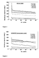
- Figure 3 shows, as an example, the discharge capacity, at current densities ranging between 18.6-744.0 mAg -1 , of the cell wherein the graphite nanofibre named GNF-6-7/2800 was used as the active material in the working electrode (see Table 3 and Figure 2 ).
- the GNF-6-7/2800 graphite nanofibres exhibit a good cyclability (retention of the discharge capacity throughout the cycling), even at high current densities. Moreover, the discharge capacities provided by these GNFs are comparable to and even higher than (at current densities > 100 mAg -1 ) those of a synthetic micrometric-size graphite used as an anode for commercial lithium-ion batteries ( Figure 4 ).
- the nanometric size of the GNFs favours the diffusion of the lithium ions in the structure and, as the current density, i.e. the charge-discharge rate in the cell, increases, this positive effect becomes more evident.
Landscapes
- Chemical & Material Sciences (AREA)
- Engineering & Computer Science (AREA)
- Chemical Kinetics & Catalysis (AREA)
- General Chemical & Material Sciences (AREA)
- Nanotechnology (AREA)
- Physics & Mathematics (AREA)
- Materials Engineering (AREA)
- Thermal Sciences (AREA)
- Textile Engineering (AREA)
- Electrochemistry (AREA)
- Inorganic Chemistry (AREA)
- Organic Chemistry (AREA)
- Composite Materials (AREA)
- Condensed Matter Physics & Semiconductors (AREA)
- General Physics & Mathematics (AREA)
- Crystallography & Structural Chemistry (AREA)
- Carbon And Carbon Compounds (AREA)
- Battery Electrode And Active Subsutance (AREA)
Applications Claiming Priority (2)
| Application Number | Priority Date | Filing Date | Title |
|---|---|---|---|
| ES201331057A ES2540005B1 (es) | 2013-07-11 | 2013-07-11 | Procedimiento de preparación de nanofibras de grafito a partir de biogás |
| PCT/ES2014/070509 WO2015004295A1 (es) | 2013-07-11 | 2014-06-23 | Procedimiento de preparacion de nanofibras de grafito a partir de biogas |
Publications (2)
| Publication Number | Publication Date |
|---|---|
| EP3045575A1 true EP3045575A1 (de) | 2016-07-20 |
| EP3045575A4 EP3045575A4 (de) | 2017-01-18 |
Family
ID=52279380
Family Applications (1)
| Application Number | Title | Priority Date | Filing Date |
|---|---|---|---|
| EP14822242.5A Withdrawn EP3045575A4 (de) | 2013-07-11 | 2014-06-23 | Verfahren zur herstellung von graphitnanofasern aus biogas |
Country Status (3)
| Country | Link |
|---|---|
| EP (1) | EP3045575A4 (de) |
| ES (1) | ES2540005B1 (de) |
| WO (1) | WO2015004295A1 (de) |
Cited By (1)
| Publication number | Priority date | Publication date | Assignee | Title |
|---|---|---|---|---|
| ES2717199A1 (es) * | 2017-12-19 | 2019-06-19 | Pamies Javier Biela | Planta de biogas |
Family Cites Families (3)
| Publication number | Priority date | Publication date | Assignee | Title |
|---|---|---|---|---|
| JP4697941B2 (ja) | 2005-05-11 | 2011-06-08 | 株式会社日本製鋼所 | 低級炭化水素の直接分解による機能性ナノ炭素及び水素の製造方法 |
| KR101021581B1 (ko) * | 2008-06-19 | 2011-03-17 | 주식회사 나노솔루션 | 바이오 매스를 이용한 탄소나노튜브 또는 탄소나노섬유합성방법 |
| ES2345805B1 (es) | 2009-03-31 | 2011-07-22 | Consejo Superior De Investigaciones Científicas (Csic) | Catalizadores de hierro para la produccion simultanea de hidrogeno y nanofilamentos de carbono mediante descomposicon catalitica de metano. |
-
2013
- 2013-07-11 ES ES201331057A patent/ES2540005B1/es not_active Expired - Fee Related
-
2014
- 2014-06-23 WO PCT/ES2014/070509 patent/WO2015004295A1/es not_active Ceased
- 2014-06-23 EP EP14822242.5A patent/EP3045575A4/de not_active Withdrawn
Cited By (3)
| Publication number | Priority date | Publication date | Assignee | Title |
|---|---|---|---|---|
| ES2717199A1 (es) * | 2017-12-19 | 2019-06-19 | Pamies Javier Biela | Planta de biogas |
| WO2019122484A1 (es) * | 2017-12-19 | 2019-06-27 | Javier Biela Pamies | Planta de biogas |
| CN111936611A (zh) * | 2017-12-19 | 2020-11-13 | J·比尔拉帕米尔斯 | 沼气设备 |
Also Published As
| Publication number | Publication date |
|---|---|
| WO2015004295A1 (es) | 2015-01-15 |
| EP3045575A4 (de) | 2017-01-18 |
| ES2540005A1 (es) | 2015-07-07 |
| ES2540005B1 (es) | 2016-04-13 |
Similar Documents
| Publication | Publication Date | Title |
|---|---|---|
| Liu et al. | In situ synthesis of MXene with tunable morphology by electrochemical etching of MAX phase prepared in molten salt | |
| Hong et al. | Bi dots confined by functional carbon as high‐performance anode for lithium ion batteries | |
| Lei et al. | Surface modification of Li‐rich Mn‐based layered oxide cathodes: challenges, materials, methods, and characterization | |
| Xiong et al. | Red phosphorus nanoparticle@ 3D interconnected carbon nanosheet framework composite for potassium‐ion battery anodes | |
| Yin et al. | Synthesis and electrochemical properties of LiNi0. 5Mn1. 5O4 for Li-ion batteries by the metal–organic framework method | |
| Liu et al. | 3D self-supported hierarchical core/shell structured MnCo 2 O 4@ CoS arrays for high-energy supercapacitors | |
| EP3326968B1 (de) | Oberflächenmodifizierter graphit, verfahren zur herstellung davon und anwendungen davon | |
| Bak et al. | Spinel LiMn 2 O 4/reduced graphene oxide hybrid for high rate lithium ion batteries | |
| Yin et al. | Influence of morphologies and pseudocapacitive contributions for charge storage in V2O5 micro/nano-structures | |
| Gürsu et al. | Preparation of N‐doped graphene powders by cyclic voltammetry and a potential application of them: Anode materials of Li‐ion batteries | |
| Bulusheva et al. | Creation of nanosized holes in graphene planes for improvement of rate capability of lithium-ion batteries | |
| Zhang et al. | Morphology‐tuned synthesis of NiCo2O4‐coated 3D graphene architectures used as binder‐free electrodes for lithium‐ion batteries | |
| Li et al. | Micrometer‐Sized, Dual‐Conductive MoO2/β‐MoO3‐x Mosaics for High Volumetric Capacity Li/Na‐Ion Batteries | |
| Khan et al. | Cobalt oxide nanoparticle embedded N-CNTs: lithium ion battery applications | |
| Yan et al. | High‐pressure induction and quantitative regulation of oxygen vacancy defects in lithium titanate | |
| Leng et al. | MOF‐derived MnV2O4/C microparticles with graphene coating anchored on graphite sheets: oxygen defect engaged high performance aqueous zinc‐ion battery | |
| Huang et al. | Carbon-coated lithium titanium phosphate nanoporous microplates with superior electrochemical performance | |
| Fan et al. | Microwave Shock Synthesis of Porous 2D Non‐Layered Transition Metal Carbides for Efficient Hydrogen Evolution | |
| Kim et al. | Electrochemical performance of Mn3O4 nanorods by N‐doped reduced graphene oxide using ultrasonic spray pyrolysis for lithium storage | |
| Kuang et al. | Metal oxide-and N-codoped carbon nanosheets: facile synthesis derived from MOF nanofibers and their application in oxygen evolution | |
| Zhang et al. | Ballmilling-assisted synthesis and electrochemical performance of LiFePO4/C for lithium-ion battery adopting citric acid as carbon precursor | |
| Bi et al. | Nickel foam deposited with borophene sheets used as a self-supporting binder-free anode for lithium-ion batteries | |
| He et al. | Three-dimensional K3V3 (PO4) 4@ Carbon core-shell coaxial nanowire networks for High-rate sodium-ion batteries | |
| Sharma et al. | Binder‐Free MoO2‐MoO3 Nanoarrays as High‐Performance Anodes for Li‐Ion Batteries | |
| Li et al. | Insight into effects of niobium on electrospun Li2TiSiO5 fibers as anode materials in lithium-ion batteries |
Legal Events
| Date | Code | Title | Description |
|---|---|---|---|
| PUAI | Public reference made under article 153(3) epc to a published international application that has entered the european phase |
Free format text: ORIGINAL CODE: 0009012 |
|
| PUAB | Information related to the publication of an a document modified or deleted |
Free format text: ORIGINAL CODE: 0009199EPPU |
|
| PUAI | Public reference made under article 153(3) epc to a published international application that has entered the european phase |
Free format text: ORIGINAL CODE: 0009012 |
|
| 17P | Request for examination filed |
Effective date: 20160211 |
|
| AK | Designated contracting states |
Kind code of ref document: A1 Designated state(s): AL AT BE BG CH CY CZ DE DK EE ES FI FR GB GR HR HU IE IS IT LI LT LU LV MC MK MT NL NO PL PT RO RS SE SI SK SM TR |
|
| AX | Request for extension of the european patent |
Extension state: BA ME |
|
| DAX | Request for extension of the european patent (deleted) | ||
| A4 | Supplementary search report drawn up and despatched |
Effective date: 20161220 |
|
| RIC1 | Information provided on ipc code assigned before grant |
Ipc: D01F 9/127 20060101ALI20161209BHEP Ipc: H01M 4/58 20100101ALI20161209BHEP Ipc: C01B 31/02 00000000ALI20161209BHEP Ipc: H01M 4/13 20100101ALI20161209BHEP Ipc: B82Y 30/00 20110101ALI20161209BHEP Ipc: C01B 31/04 00000000AFI20161209BHEP |
|
| STAA | Information on the status of an ep patent application or granted ep patent |
Free format text: STATUS: REQUEST FOR EXAMINATION WAS MADE |
|
| STAA | Information on the status of an ep patent application or granted ep patent |
Free format text: STATUS: THE APPLICATION IS DEEMED TO BE WITHDRAWN |
|
| 18D | Application deemed to be withdrawn |
Effective date: 20170720 |