EP3045635A1 - Mécanisme d'aide à l'ouverture et à la fermeture de fenêtre ou de porte - Google Patents
Mécanisme d'aide à l'ouverture et à la fermeture de fenêtre ou de porte Download PDFInfo
- Publication number
- EP3045635A1 EP3045635A1 EP15200421.4A EP15200421A EP3045635A1 EP 3045635 A1 EP3045635 A1 EP 3045635A1 EP 15200421 A EP15200421 A EP 15200421A EP 3045635 A1 EP3045635 A1 EP 3045635A1
- Authority
- EP
- European Patent Office
- Prior art keywords
- wing
- opening
- spring
- closing
- window
- Prior art date
- Legal status (The legal status is an assumption and is not a legal conclusion. Google has not performed a legal analysis and makes no representation as to the accuracy of the status listed.)
- Withdrawn
Links
Images


Classifications
-
- E—FIXED CONSTRUCTIONS
- E05—LOCKS; KEYS; WINDOW OR DOOR FITTINGS; SAFES
- E05D—HINGES OR SUSPENSION DEVICES FOR DOORS, WINDOWS OR WINGS
- E05D15/00—Suspension arrangements for wings
- E05D15/48—Suspension arrangements for wings allowing alternative movements
- E05D15/52—Suspension arrangements for wings allowing alternative movements for opening about a vertical as well as a horizontal axis
- E05D15/5202—Suspension arrangements for wings allowing alternative movements for opening about a vertical as well as a horizontal axis with non-horizontally extending checks
-
- E—FIXED CONSTRUCTIONS
- E05—LOCKS; KEYS; WINDOW OR DOOR FITTINGS; SAFES
- E05F—DEVICES FOR MOVING WINGS INTO OPEN OR CLOSED POSITION; CHECKS FOR WINGS; WING FITTINGS NOT OTHERWISE PROVIDED FOR, CONCERNED WITH THE FUNCTIONING OF THE WING
- E05F1/00—Closers or openers for wings, not otherwise provided for in this subclass
- E05F1/08—Closers or openers for wings, not otherwise provided for in this subclass spring-actuated, e.g. for horizontally sliding wings
- E05F1/10—Closers or openers for wings, not otherwise provided for in this subclass spring-actuated, e.g. for horizontally sliding wings for swinging wings, e.g. counterbalance
- E05F1/1041—Closers or openers for wings, not otherwise provided for in this subclass spring-actuated, e.g. for horizontally sliding wings for swinging wings, e.g. counterbalance with a coil spring perpendicular to the pivot axis
-
- E—FIXED CONSTRUCTIONS
- E05—LOCKS; KEYS; WINDOW OR DOOR FITTINGS; SAFES
- E05F—DEVICES FOR MOVING WINGS INTO OPEN OR CLOSED POSITION; CHECKS FOR WINGS; WING FITTINGS NOT OTHERWISE PROVIDED FOR, CONCERNED WITH THE FUNCTIONING OF THE WING
- E05F1/00—Closers or openers for wings, not otherwise provided for in this subclass
- E05F1/08—Closers or openers for wings, not otherwise provided for in this subclass spring-actuated, e.g. for horizontally sliding wings
- E05F1/10—Closers or openers for wings, not otherwise provided for in this subclass spring-actuated, e.g. for horizontally sliding wings for swinging wings, e.g. counterbalance
- E05F1/14—Closers or openers for wings, not otherwise provided for in this subclass spring-actuated, e.g. for horizontally sliding wings for swinging wings, e.g. counterbalance with double-acting springs, e.g. for closing and opening or checking and closing no material
-
- E—FIXED CONSTRUCTIONS
- E05—LOCKS; KEYS; WINDOW OR DOOR FITTINGS; SAFES
- E05F—DEVICES FOR MOVING WINGS INTO OPEN OR CLOSED POSITION; CHECKS FOR WINGS; WING FITTINGS NOT OTHERWISE PROVIDED FOR, CONCERNED WITH THE FUNCTIONING OF THE WING
- E05F5/00—Braking devices, e.g. checks; Stops; Buffers
- E05F5/02—Braking devices, e.g. checks; Stops; Buffers specially for preventing the slamming of swinging wings during final closing movement, e.g. jamb stops
-
- E—FIXED CONSTRUCTIONS
- E05—LOCKS; KEYS; WINDOW OR DOOR FITTINGS; SAFES
- E05F—DEVICES FOR MOVING WINGS INTO OPEN OR CLOSED POSITION; CHECKS FOR WINGS; WING FITTINGS NOT OTHERWISE PROVIDED FOR, CONCERNED WITH THE FUNCTIONING OF THE WING
- E05F5/00—Braking devices, e.g. checks; Stops; Buffers
- E05F5/06—Buffers or stops limiting opening of swinging wings, e.g. floor or wall stops
- E05F5/08—Buffers or stops limiting opening of swinging wings, e.g. floor or wall stops with springs
-
- E—FIXED CONSTRUCTIONS
- E05—LOCKS; KEYS; WINDOW OR DOOR FITTINGS; SAFES
- E05Y—INDEXING SCHEME ASSOCIATED WITH SUBCLASSES E05D AND E05F, RELATING TO CONSTRUCTION ELEMENTS, ELECTRIC CONTROL, POWER SUPPLY, POWER SIGNAL OR TRANSMISSION, USER INTERFACES, MOUNTING OR COUPLING, DETAILS, ACCESSORIES, AUXILIARY OPERATIONS NOT OTHERWISE PROVIDED FOR, APPLICATION THEREOF
- E05Y2201/00—Constructional elements; Accessories therefor
- E05Y2201/40—Motors; Magnets; Springs; Weights; Accessories therefor
- E05Y2201/404—Function thereof
- E05Y2201/408—Function thereof for braking
-
- E—FIXED CONSTRUCTIONS
- E05—LOCKS; KEYS; WINDOW OR DOOR FITTINGS; SAFES
- E05Y—INDEXING SCHEME ASSOCIATED WITH SUBCLASSES E05D AND E05F, RELATING TO CONSTRUCTION ELEMENTS, ELECTRIC CONTROL, POWER SUPPLY, POWER SIGNAL OR TRANSMISSION, USER INTERFACES, MOUNTING OR COUPLING, DETAILS, ACCESSORIES, AUXILIARY OPERATIONS NOT OTHERWISE PROVIDED FOR, APPLICATION THEREOF
- E05Y2201/00—Constructional elements; Accessories therefor
- E05Y2201/40—Motors; Magnets; Springs; Weights; Accessories therefor
- E05Y2201/47—Springs
- E05Y2201/496—Double acting springs
Definitions
- the invention relates to a device for a window or a door according to the preamble of claim 1.
- the invention relates to devices for Drehkipperiel-, rotary wing, Kipperiel- or Parallelabstelleriel- for windows or doors.
- the part to be opened and closed will be referred to as a wing and the part fixed to it as a frame.
- the device has the task by the opening and closing support to support the wing to the frame from a closed position or from an opening end position and to generate a damping during movement in the closed position and in the opening end position.
- This can be when opening, for example, in the opening end position for tilting and closing the wing from the tilted opening end position in the closed position, control the opening speed and adversely affect forces and impact noises occurring on the fitting.
- the occurring forces of such a system are dependent on the initial speed and the mass, so that in particular large-scale windows or doors can burden the espagnolette fitting and cause loud stop noises in the opening end position and closing position.
- the large weight of the wing also complicates the closing process from the opening end position. Therefore, it is further desired to ensure by the use of the easy-to-install device to facilitate the closing process from the opening end position in the applied closed position and from the closed position to the opening end position.
- the necessary manual force for the execution of the tilting of the wing is neglected by frictional influences by the handle height, wing mass and position of the blade center of gravity with respect to the tipping point.
- the shift of the position of the center of gravity of the wing relative to the tipping point of the wing, the lower horizontal spar of the wing to the frame, the tilting, causes a reversal of the operating force on the operating handle.
- the device may also have the task of forming an additional escapement against the blade falling in a gust of wind, while acting as a safeguard against possible falling out of the wing.
- the invention relates to a device which is used as a relief and assistance in the operation of the window or the door from the closed position to the opening end position and vice versa in the closed position of the wing.
- fittings are known that forward via espagnolette and corner deflections an actuating movement of an operating lever over more than one or all sides of the wing to lock at several distributed the wing circumference by closure devices locking and by a display device a rotational and / or Kippö Stamms sued the Wing against the frame effect.
- a fitting part of this kind is by the DE 2001369 A1 already known.
- the known device makes it possible to facilitate the opening and closing of windows and doors, which consists of a pivot arm arranged between the pivotable part and a sliding guide.
- the device is attached to an inner side wall of a frame part resting, wherein a pivoting arm connects a wing articulated.
- the other free end of the pivot arm is rotatably mounted with a slidable in the device of a guide slider.
- an elastic means is arranged, which counteracts the tendency of the wing when tilting down to counteract, wherein the wing rotates about a hinge and the elastic element generates a counterbalance.
- the devices for components in the form of sliding doors and partitions in interior design are very expensive in construction, have a variety of components and are expensive to manufacture.
- a combination for accelerating from the situation located in the closed position of the sash to the frame out into the tilted, with damping opening end position and from the opening end position in the applied with damping effect closing position is not known.
- WO 2013/135545 A1 comprising a combined device for decelerating and accelerating a wing of windows or doors, and an espagnolette drivable in a fitting groove and in a folding room, which includes an opening scissors.
- the opening width of the Ausstellschere is pivotally articulated in a tilted position by a on the one hand on the frame and on the other hand on the wing Swivel arm limited by this engages with a pin or the like.
- the longitudinal guide forms at its Kippö Samuelsend ein the wing end facing a limit stop for the pin.
- the device is concealed in the rebate and / or the fitting groove between the frame and the wing mountable.
- An arranged on the device pull rod forms the movable coupling with the pivot arm, which is arranged on the frame with a hinge movably coupled Ausstellschere, acting between the tie rod and the pivot arm in the longitudinal direction of the fitting groove, a force storage.
- the energy storage counteracts the movement of the wing in the Kippö Maschinensend too, so that a slowed movement of the wing is effected. Furthermore, the wing from the securely held Kippö Maschinensend ein - with the release of the stored force of the energy storage - accelerated and transferred almost automatically in the closed position.
- the device described above can be mounted concealed in the rebate of the window or door, but the device proves to be expensive to manufacture and is only suitable to the wing in the Kippö Stammsend ein to damp or brake and the wing from the Kippö Stammsend ein with Accelerate release of the stored force of the energy accumulator and transfer to the closed position.
- the present embodiment of the espagnolette also allows no linear translation, which can affect the device in an advantageous manner.
- the invention has for its object to provide a device for opening and closing support of the wing to the frame from a closed position, and from an opening end position, and to allow a damping of the movement in the closed position and in the opening end position, the good optics of the window or the door is inexpensive and can be mounted in a simple, fast, safe and precise manner with little space and adjusted and eliminates the above disadvantages.
- a combined deceleration and acceleration device which, to assist and facilitate the opening and closing of a wing of a window or door, acts at least one between a frame and the wing of the window or the door for opening and closing support Having spring device, and is operatively connected to a Ausstellschere whose opening width can be limited in an opening end position by a hinged on the one hand on the frame and on the other hand on the wing extension arm.
- the spring device is spring-loaded in a closed position of the wing and accelerates the wing with movement of the extension arm from the closed position of the wing with remove from the frame in the direction of an opening pivoting position and returns the stored spring force.
- the spring force of the spring device is stored constructively, so that the wing is moved damping in the opening end position.
- the stored energy of the spring device is released and accelerates the wing in the direction of a Sch Strukturschwenklage.
- the spring force of the spring device is stored constructively, so that the wing dampening reaches the closed position.
- the spring device relaxes during the opening process from the adjacent closed position of the wing to the frame, energy is automatically released, which causes a support of the opening of the wing from the closed position in the direction of the opening pivot position.
- the spring device Upon reaching the opening pivot position, the spring device is relaxed and builds up with further actuation of the wing in the direction of the opening end position, so that the spring device stores the energy upon reaching the opening end position.
- the stored energy discharges with relaxation of the spring device into the Sch thoroughlyschwenklage.
- the relaxed spring device is tensioned with further movement of the wing from the closing pivot position in the direction of the closed position and builds up energy that is stored in the closed position.
- the wing In opening pivot position and in closing pivot position, the wing is located to the frame in a partially open position, with a fully released energy of the spring device.
- the comfort operation by the device thus facilitates the operation of the tilting operation in the case of large and heavy wings, wherein the device can likewise influence the turning or stopping operation in an advantageous manner.
- the manual force on the actuating handle, for example, to perform the tilting operation is reduced.
- the force resulting from the displacement of the center of gravity of the wing during the tilting process is stored in the spring device.
- the previously stored spring force supports and reduces the necessary manual force on the actuating handle for performing the tilting operation.
- a reduction of the dynamics of the wing succeeds by the optimal damping effect of the spring means on the wing in the direction of the closed position and the opening end position.
- the damping effect also reduces the loads on the espagnolette fitting components, in particular the hinge components, the window or the door.
- the device is used in rotary, tilt or turn-tilt windows or - Doors their use. It is also conceivable to mount the device in Parallelabstellpper or doors.
- the device adapts advantageously to the dimensions, for example in height to the in the rebate and / or the fitting by the actuating handle operably arranged espagnolette , As a result, a compact and simple construction of the device is achieved.
- the device is dimensioned in the cross-sectional dimensions so that an assembly requires no further processing on the window or the door.
- the components on which the device is based in particular the components for performing a functional actuation, are aligned in the longitudinal direction of the fitting groove.
- the spring device comprises a compression spring as a helical compression spring, the compression spring acting in the longitudinal direction of the fitting groove, claimed from the closed position of the wing out in the direction of the opening pivot position to pressure is and is claimed with movement of the extension arm of the Ausstellschere from the opening pivot position in the direction of the opening end position of the wing to train, with relaxed closing movement of the wing and movement of Ausstellarms from the ⁇ réellesendlage out in the direction of Schinneschwenklage, relaxes the claimed compression spring, and the compression spring is loaded with movement of the extension arm from the closing pivot position in the direction of the closing position of the wing to pressure.
- the compression spring is actively connected to the opening arm of the Ausstellschere, wherein a free end of the compression spring non-positively and / or positively, for example screwed onto a pin attached to a driver, and a rotatable end of the stay attached to a longitudinally displaceable hinged to the Ausstellschere driver.
- the compression spring engages over the length of their turns a round rod or is held by a arranged outside the turns sleeve in the longitudinal direction of the fitting leader dimensionally stable encompassing. Positive and / or non-positively connected, the round rod or sleeve on a fortified in the direction of the fitting groove on the wing faceplate of the Ausstellschere the device.
- the spring device has an adjustment device for spring stiffness.
- the active spring length is changed with the actively loaded turns in the opening pivot position or closing pivot position or between the transition point of the opening to closing support. Based on an equation or diagram depending on the position of the center of gravity of the wing and its mass, the setting of the active windings for the spring stiffness can be determined and adjusted.
- the spring preload can also be adjusted via the adjusting device.
- the determination of the adjustment of the spring bias of the spring means is carried out either by means of an equation or a diagram, if the position of the center of gravity of the wing is known.
- the setting of the spring preload for example, in a tiltable wing by a tilt test, determine.
- the number of turns of the compression spring is divided into a number of active turns and a number of inactive, passive turns.
- the adjusting device has a blocking element which consists of a Klipsring, snap ring, split pin or other known connection components.
- the Klipsring, snap ring or split pin passes through a predetermined distance having free space between the turns of the compression spring, the clip ring or snap ring engage in the round rod gradual grooves arranged or infinitely, spindle-like grooves and the sapwood on the round rod arranged holes and form a and / or force-locking connection effect.
- a further advantageous embodiment of an adjustment, with which the spring stiffness can be adjusted consists of a threaded spindle or threaded rod, which rotatably guided with a free end with a fixed in Wirkverinrung the sleeve on the faceplate Ausstellschere web through a through hole or through another through hole , is connected to the through-hole with each arranged on both sides of the web nuts non-positively.
- the distance between the first hinged end and the second hinged end of the spring device having compression spring is adjustable.
- a first advantageous embodiment of the biasing means consists of a threaded pin, the form-fitting and / or non-positively, for example, by a retaining ring, held and rotatably supported by meshing with a shoulder in a bore forms a first coupling point, and with a second tapered in cross-section Journal in a receiving bore of the round rod in the longitudinal direction leading slidably having the second coupling point, wherein the threaded pin and the round rod form a central axis.
- the threaded pin rotatably receives a threaded sleeve, which is operatively connected to the end of the compression spring and linear leader, for example, by a non-positively attached to the threaded sleeve dowel pin or dowel pin, mounted in a longitudinal direction of the faceplate elongated hole of the Ausstellschere , wherein the threaded pin at the coupling point to the driver facing out, a tool engagement preferably a hexagon socket, and by means of a tool causes an adjustment of the threaded sleeve, so that the distance of the compression spring can be changed.
- a further advantageous embodiment of the biasing device which has a threaded spindle or threaded rod, which rotatably guided with a free end with a fixed in Wirkverinrung the sleeve on the faceplate Ausstellschere web through a through hole, each with two Pages of the web arranged nuts is frictionally connected.
- a head on the other free end engages by means of external windings between the turns of the compression spring on the inside, via a tool by releasing the remote from the compression spring nut and turning the nut directed to the compression spring, depending on the direction of the threaded rod, the compression spring tensioned by the threaded rod or relieved, is relaxing.
- Another simple and inexpensive to manufacture embodiment of the spring device results from two compression springs as helical compression springs, acting in the longitudinal direction of the fitting groove, from the closed position of the wing to the frame out the first pressure-loaded compression spring in the direction of the opening pivot position emits the stored energy of the spring force and finally completely released and wherein with movement of the extension of the Ausstellschere from the opening pivot position in the direction of the opening end position of the wing to the frame, the second relieved compression spring is subjected to pressure and thereby Energy building stores.
- the compression springs are actively connected to the extension arm of the Ausstellschere, wherein the rotatable end of the extension arm is attached to a longitudinally displaceable hinged on the Ausstellschere the fitting groove driver.
- the compression springs are operatively connected, each having one end to a web of a driver depending on the opening position of the extension arm and are held by each arranged on a fixed to the faceplate stop fixations with the other other ends leader.
- Conceivable is a combination of the design of the spring device, consisting of two compression springs as helical compression springs, with the present adjustment and biasing devices.
- the tension springs act in the longitudinal direction of the fitting groove. From the closed position of the wing to the frame out a first tensile loaded in the direction of the opening pivot position releases the stored energy of the spring force completely released, with movement of the extension of the Ausstellschere from the opening pivot position in the direction of the opening end position of the wing to the frame, the second relieved Tension spring is subjected to train while storing energy building.
- the tension springs are actively connected to the extension arm of the Ausstellschere, wherein the rotatable end of the extension arm is attached to a longitudinally displaceable hinged to the Ausstellschere the fitting groove driver.
- the tension springs are operatively connected, each having one end to a web of a driver depending on the opening position of the extension arm and are held by a respective attached to the wing faceplate pins with the respective other ends.
- Conceivable is a combination of the design of the spring device, consisting of two tension springs as fferenzugfedern, with the present adjustment and biasing devices.
- the spring device For easy design and connection of the device during assembly, form the spring device together with the adjuster, the biasing device and the Ausstellschere a structural unit. This is a clear separation of the device and the espagnolette fitting of the window or door. Nevertheless, the assembly of the device is maintained by a positive and / or non-positive connection. Due to the adapted dimensions of the device for espagnolette, this also creates an adaptable in its length to the espagnolette fitting device that can be mounted as needed on both the vertical spar or the horizontal spar of the wing.
- the Ausstellschere on a handlebar which is pivotally mounted with a free end of the faceplate and with the other free End is slidably guided via a pin mounted on the handlebar in a slot in the extension arm, with a link having on the handlebars with the intervention of a driver attached to the slide follower, the extension arm forcibly controlled is pivotable and allows a linear thrust movement of the wing-side Ausstellarmwindgelenken.
- the assembled conventional espagnolette fitting in operative connection with latching engagements disposed on the frame, is capable of effecting a sealing action by pressure.
- the guide fitting has an inlet and outlet opening for uncoupling for the guide pin from the guide groove, so that the wing without the influence of the device, for example in a tilt-and-turn window or door in tiltable operative connection of the device at a Drehrschafts ein the espagnolette, can be opened.
- a securing device is further provided, which prevents the self-emergence of the guide pin of the extension arm in a tilt-and-turn window or door in tiltable operative connection from the inlet and outlet opening.
- the guide fitting For easy design and connection of the guide fitting during assembly to the frame, the guide fitting has a base plate with mounting holes for mounting screws for attachment to the frame.
- the guide slide in a slot of Base plate slidably guided in the longitudinal direction of the fitting groove and can be forcibly moved to the appropriate position provided.
- the formation of the securing device proves in a production of an L-shaped strip material.
- the safety device is fixed to the base plate non-positively and / or positively.
- An increase in the reliability of the coupling and uncoupling of the guide pin with the Ausstellschere, for example, in a tilt and turn window or door, in the respective positions of the closed position, the rotation readiness position and Kippö Maschinenslage the espagnolette is thereby made possible that the securing device with the guide slide in the respective positions by a fixing device is releasably coupled and thus the guide pin during the Kippö Maschinensschi in the guide groove of the guide slide movably supports.
- the releasable coupling of the fixing device is a latching / snap connection.
- the guide slide and the securing device are spaced transversely to the fitting groove of the wing and form one Gap, which produces the free field of action of the guide pin of the stay of the Ausstellschere.
- the guide pin of the extension is transferred by compulsory displacement of the guide slide in the guide, wherein the securing device with an arm closes the inlet and outlet of the guide slide.
- the invention relates to a method for operating a device for assisting and facilitating the opening and closing of a wing of a window or door, in which between a frame and the wing of the window or the door spring means is provided, wherein the spring means in operative connection with a scissors is.
- the changing effect of accelerating or damping the wing by an exchange of spring force or energy of the spring device in the closed position and succeeds in the opening end position which is achieved by the spring means in the direction of the closed position or opening end position, spring force or energy applied to store and dampen the wing and with delivery of the stored spring force or energy from the closed position or opening end position allows acceleration of the wing, wherein the spring force of the spring device is relaxed and re-tensioned in an opening or closing pivoting position.
- the simple coupling of the device to the espagnolette fitting and the fact that the device is designed as a unit independent of the espagnolette fitting, allows mounting with the espagnolette fitting or, if necessary, a subsequent mounting on the already pre-assembled espagnolette fitting.
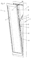
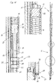
- a device 1 which as a relief and assistance in the operation of the window or door 3 from the closed position to Fig. 4 in the opening end position Fig. 1 and vice versa in the closed position of a wing 2 to the frame 4 is used.
- espagnolettes 77 are known which forward via espagnolette and corner deflections an actuating movement of an operating lever over more than one or all sides of the wing 2, at several the wing circumference distributed locations by locking devices a lock and by a display device a rotary and / or Kippö Stammswolf or parallel shutdown of the wing 2 against the frame 4 to effect.
- the combined decelerating and accelerating device 1 for the wing 2 of windows or doors 3 provided to assist and facilitate the opening and closing of a wing 2 of a window or door 3 at least one between the frame 4 and the wing 2 of the window or the door 3 for opening and closing support acting spring means 5, and is operatively connected to a Ausstellschere 6 whose opening width is limited in an opening end position by a hinged on the one hand on the frame 4 and on the other hand pivotally hinged 2 Ausstellarm 7.
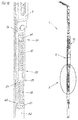
- the spring device 5 In the closed position of the wing 2 to the frame 4 after 4 to 5 , The spring device 5, based on the unloaded state of the spring device 5 due to a first change in length 8 spring force acts stored and accelerates the wing 2 with movement of the stay 7 from the closed position of the wing 2 with removal from the frame 4 in the direction of an opening pivot position Fig. 2a and releases the stored spring force.
- the spring force of the spring means 5 Upon further change of the distance of the wing 2 to the frame 4 with movement of the extension arm 7 from the opening pivot position in the direction of a limited opening end position of the wing 2 after Fig. 1 to 3 , The spring force of the spring means 5, starting from the unloaded state of the spring means 5 at a second change in length 9 after Fig. 2b and Fig.
- the relaxed spring device 5 is with further movement of the wing 2 from the Schröschwenklage in the direction of the closed position to Fig. 4 excited and builds energy which is stored in the closed position.
- Fig. 2a In opening pivot position and in closing pivot position Fig. 2a is the wing 2 to the frame 4 in a part open position, an intermediate layer or transitional position, with one of the spring means 5 relieved completely released energy.
- the device 1 can be used in the operating modes of the wing 2 for a tilting, turning or shutdown, which will be discussed in more detail below on the tilting.
- the manual force on the actuating handle, not shown, for example, to perform the tilting operation is reduced.
- the force resulting from the displacement of the center of gravity of the wing 2 during the tilting process is stored in the spring device 5.
- the previously stored spring force supports and reduces the necessary manual force on the actuating handle for performing the tilting operation.
- a reduction in the dynamics of the wing 2 by the optimal damping effect of the spring device 5 on the wing 2 in the direction of the closed position and the opening end position succeeds.
- the damping effect also reduces the loads on the espagnolette fitting components 77, in particular the hinge components, the window or the door 3.
- the device 1 in the dimensions, for example in the height of the in the rebate space 11 and / or the fitting groove 10 operatively arranged by the actuating handle arranged drive rod fitting 77 adapted.
- the device 1 is dimensioned in the cross-sectional dimensions and in the length so that an assembly requires no further processing on the window or the door 3.
- the functionally acting components of the device 1 are aligned in the longitudinal direction of the fitting groove 10 ( Fig. 4 ).
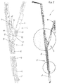
- the spring device 5 after Fig. 1 to Fig. 6 a compression spring 12 as a helical compression spring, wherein the compression spring 12 acting in the longitudinal direction of the fitting groove 10, from the closed position to Fig. 4 the wing 2 out in the direction of the opening pivot position Fig. 2a is loaded on pressure and with movement of the stay 7 of the Ausstellschere 6 from the opening pivot position in the direction of the opening end position Fig. 1 of the wing 2 is loaded to train, with reverse closing movement of the wing 2 and movement of the stay 7 from the opening end position after Fig. 1 out in the direction of the closing pivot position Fig. 2a , Relaxed on train pressure spring 12, and the compression spring 12 is loaded with movement of the stay 7 from the Sch concentratedschwenklage in the direction of the closed position of the wing 2 to pressure.
- the compression spring 12 is after Fig. 3 actively operatively connected to the stay 7 of the stay-scissors 6, wherein a free end 13 of the compression spring 12 force and / or positive fit according to an embodiment of Fig. 3 and Fig. 6 turned on a pin 15 attached to the pin and a rotatable end 14 of the stay 7 are attached to the longitudinally slidably hinged to the Ausstellschere 6 driver 15.
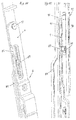
- Fig. 5 to Fig. 7 surrounds the compression spring 12 over the length of their turns 16 a rod 17 or is after Fig. 10 held by a outside of the windings 16 arranged sleeve 18 in the longitudinal direction of the fitting groove 10 leading dimensionally encompassing.
- the round rod 17 or the sleeve 18 is connected in a positive and / or non-positive manner to a faceplate 19 of the setting-out scissors 6 of the device 1 attached to the wing 2 in the direction of the fitting groove 10.
- the connection itself is not shown further, but can be achieved, for example, by a riveted connection. a screw connection or a connection can be created by a welding process.
- the spring device 5 has an adjusting device 20, 25 for spring stiffness.
- the active spring length is changed with the actively loaded turns 21 in the opening pivot position or closing pivot position or between the transition point of the opening to closing support.
- the setting of the active windings 21 for the spring stiffness can be determined and adjusted.
- the spring preload can also be adjusted via the adjusting device 20, 25.
- the determination of the adjustment of the spring bias of the spring means 5 is carried out either by means of an equation or a diagram, if the position of the center of gravity of the wing 2 is known.
- the setting of the spring preload for example, in a tiltable wing 2 by a tilt test, determine.
- the number of turns 16 of the compression spring 12 is divided into a number of active, claimed turns 21 and a number of inactive, passive windings 22nd
- the adjuster 20 after Fig. 5 to 6 a blocking element 23, which consists in this embodiment of a clip ring or snap ring. But there are also other connection components conceivable.
- the clip ring or snap ring goes through Fig. 5 a space having a predetermined distance between the turns 16 of the compression spring 12, wherein the clip ring or snap ring in the round rod 17 arranged in stages grooves or continuously form spindle-like grooves 24 and a positive and / or non-positive connection cause.
- an adjusting device 25 consists of a threaded spindle or threaded rod 26 which rotatably with a free end 27 with an effective extension of the sleeve 18 on the faceplate 19 of the stay scissors 6 fixed web 28 through a through hole 29 or through a further through hole guided on the through hole 29 with each of both sides of the web 28 arranged nuts 30, 31 is non-positively connected. It takes effect Fig.
- the distance 40, 21 between the first hinged end 13 and the second hinged end 41, 32 of the spring means 5 having compression spring 12 is adjustable.
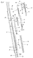
- a first advantageous embodiment of the biasing device 39 after Fig. 7 to 9 Consists of a threaded pin 42 which by interlocking with a shoulder 43 in a bore 44 on the driver 15 form and / or non-positively according to an embodiment of Fig. 8 held by a retaining ring and rotatably mounted a first coupling point 45 forms, and with a second tapered in cross-section pin 46 in a receiving bore 47 of the round rod 17 in the longitudinal direction leading sliding the second coupling point 48, wherein the threaded pin 42 and the rod 17 has a central axis 49th form.
- the grub screw 42 receives a threaded sleeve 50 rotatably, which is operatively connected to the end 13 of the compression spring 12 and, for example, by a non-positively attached to the threaded sleeve 50 cylinder pin or dowel pin Fig. 9 a straight leader in a longitudinal direction of the faceplate 19 arranged slot 51 of the Ausstellschere 6 is mounted, wherein the threaded pin 42 pointing to the coupling point 45 to the driver 15, a tool engagement preferably a hexagon socket 52, and causes an adjustment of the threaded sleeve 50 by means of a tool , so that the distance 40 of the compression spring 12 can be changed.
- FIG. 10 to 11 Another embodiment of the pretensioner 53 is after Fig. 10 to 11 provided, which has a threaded spindle or threaded rod 26 which rotatably guided with a free end 27 with an effective extension of the sleeve 18 on the faceplate 19 of the Ausstellschere 6 fixed web 28 through a through hole 29, each with arranged from both sides of the web 28 nuts 30, 31 is positively connected.
- a at the other free end 32 having head 33 engages by means of external windings 34 between the turns 16 of the compression spring 12 inside 35, wherein a tool by releasing the remote from the compression spring 12 nut 31 and turning the compression spring 12 directed nut 30, depending on Direction of adjustment of the threaded rod 26, the compression spring 12 by the threaded rod 26 tensioned or relieved, is relaxed.
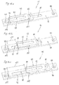
- a further embodiment of the spring device 5 is according to the Fig. 12 demonstrated.
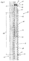
- two compression springs 54, 55 act as helical compression springs in the longitudinal direction of the fitting groove 10, wherein from the closed position of the wing 2 to the frame 4 out the first compression spring 54 claimed to pressure, in the direction of the opening pivot position Fig. 2a the stored energy of the spring force and finally releases completely, with with movement of the stay 7 of the Ausstellschere 6 from the opening pivot position in the direction of the opening end position Fig. 1 of the wing 2 to the frame 4, the second unloaded compression spring 55 is subjected to pressure while storing energy building.
- the pressure springs 54, 55 acting in the spring device 5 are actively connected to the deployment arm 7 of the deployment scissors 6 for functional transfer, the rotatable end 14 of the deployment arm 7 being fastened to a carrier 56 which is longitudinally displaceably linked to the deployment scissors 6 of the fitting groove 10.
- the compression springs 54, 55 with one end 57, 58 operatively connected to a web 59 of a driver 56 depending on the opening position of the extension arm 7 and are arranged in each case on a fixed to the wing 2 faceplate 60 stop fixings 61, 62 with the respective other Ends 63, 64 held leader.
- a further embodiment of the spring device 5 results from two tension springs 65, 66 as Screw tension springs after Fig. 13 ,
- the tension springs 65, 66 in the longitudinal direction of the fitting groove 10 acting.
- From the closed position to Fig. 4 of the wing 2 to the frame 4 out is a first claimed to train tension spring 65 in the direction of the opening pivot position from the stored energy of the spring force, which is finally completely released, with movement of the stay 7 of the Ausstellschere 6 from the opening pivot position Fig. 2a in the direction of the opening end position of the wing 2 to the frame 4, the second unloaded tension spring 66 is claimed to train while energy builds up.
- the tension springs 65, 66 acting in the spring device 5 follow Fig. 13 are actively connected to the deployment arm 7 of the stay scissors 6 for functional transmission, wherein the rotatable end 14 of the stay 7 is attached to a longitudinally displaceable on the Ausstellschere 6 of the fitting groove 10 driver 67.
- the tension springs 65, 66 with one end 68, 69 operatively connected to a web 70, 71 of a driver 67 depending on the opening position of the stay 7 and are each arranged by a fixed to the wing 2 face plate 72 pins 73, 74 with the respective other ends 75, 76 held.
- the device 1 consists of the spring device 5, the adjusting device 20, 25, the biasing means 39, 53 and the Ausstellschere 6 and forms a structural unit.
- the assembly of the device 1 does not occur in dependence of the espagnolette 77. Nevertheless, the assembly of the device 1 is maintained by a positive and / or frictional connection. Due to the adapted dimensions of the device 1 to the espagnolette 77 thereby also creates an adjustable in length on the espagnolette fitting device 1, which can be mounted as needed both on the vertical bar or on the horizontal spar of the wing 2.
- the device in particular the Ausstellschere 6, independently and in conjunction with a manually or motor-driven espagnolette fitting 77 in the fitting groove 10 and in the rebate space 11 and arrange.
- the assembled conventional espagnolette fitting 77 in operative connection with locking engagements disposed on the frame 4, is capable of effecting a sealing action by pressure.
- the Ausstellschere 7 with a frame 4 arranged on the guide fitting 91 can be coupled or coupled.
- the stay 7 of the stay-scissors 6 to the frame 4 facing out by means of a guide pin 90 with the frame 4 attached to the guide fitting 91 in a guide groove 92 of a guide slide 93 leading stored.
- a securing device 95 is provided, which prevents the self-emergence of the guide pin 90 of the extension arm 7 from the inlet and outlet opening 94.
- the guide fitting 91 For mounting the guide fitting 91 to the frame 4, the guide fitting 91 after Fig. 16 a base plate 96 with mounting holes 97 for mounting screws for attachment to the frame 4.
- the Guide slide 93 In order to prevent leakage of the guide pin 90 from the guide groove 92 during movement of the wing 2 to the frame 4 from the closed position in the opening end position preferably Kippö Stammlage and to allow entry and exit of the guide pin 90 of the Ausstellschere 6 to the guide fitting 91, is the Guide slide 93 after Fig. 16 in a slot 98 of the base plate 96 slidably guided in the longitudinal direction of the fitting groove 10 and can be forcibly moved to the correspondingly provided position.
- the securing device 95 consists of an L-shaped strip material. Attached is the securing device 95 on the base plate 96 either by force and / or positive engagement.
- the connection of the guide pin 90 of the Ausstellschere 6 to the guide fitting 91 must be designed to be coupled and uncoupled.
- the securing device 95 in the respective positions of the closed position, the rotational readiness position and Kippö réelleslage the espagnolette 77, releasably coupled to the guide slide 93 in the respective positions by a fixing device 100, wherein the guide pin 90 during the Kippö Maschinensschi after Fig. 16a and Fig. 17a is movably mounted in the guide groove 92 of the guide slide 93.
- the releasable coupling of the fixing device 100 is designed as a latch / snap connection.
- the guide slide 93 and the securing device 95 are spaced transversely to the fitting groove 10 of the wing 2 and form a gap 101, which establishes the free operating field of the guide pin 90 of the stay 7 of the Ausstellschere 6.
- the guide pin 90 of the stay 7 is by compulsory Moving the guide slide 93 transferred into the guide groove 92, wherein the securing device 95 with an arm 102, the inlet and outlet opening 94 of the guide slide 93 closes ( Fig. 16a and Fig. 17a ).
- the device 1 after Fig. 17 or Fig. 5 on the faceplate 19 and at the end of the base plate 96 of the guide fitting 91 at a right angle to the guide fitting 91 facing web 103, which forms a Aushebetik for the window or the door 3.
- the invention relates to a method for operating a device 1 for assisting and facilitating the opening and closing of a wing 2 of a window or a door 3 Fig. 1 to 4 in which between a frame 4 and the wing 2 of the window or door 3, a spring means 5 is provided, wherein the spring means 5 is in operative connection with a Ausstellschere 6, that depending on the direction of movement of the wing 2 to the frame 4 in a closed position Fig. 4 or in an opening end position Fig. 1 , in alternation accelerating or damping of the wing 2 is achieved, wherein the changing effect of accelerating or damping the wing 2 by an exchange of the spring force or energy of the spring means 5 in the closed position after Fig.
Landscapes
- Engineering & Computer Science (AREA)
- Mechanical Engineering (AREA)
- Closing And Opening Devices For Wings, And Checks For Wings (AREA)
Applications Claiming Priority (1)
| Application Number | Priority Date | Filing Date | Title |
|---|---|---|---|
| DE102015000452.2A DE102015000452A1 (de) | 2015-01-15 | 2015-01-15 | Vorrichtung zur Unterstützung und Erleichterung des Öffnens und Schließens für ein Fenster oder eine Tür |
Publications (1)
| Publication Number | Publication Date |
|---|---|
| EP3045635A1 true EP3045635A1 (fr) | 2016-07-20 |
Family
ID=54850110
Family Applications (1)
| Application Number | Title | Priority Date | Filing Date |
|---|---|---|---|
| EP15200421.4A Withdrawn EP3045635A1 (fr) | 2015-01-15 | 2015-12-16 | Mécanisme d'aide à l'ouverture et à la fermeture de fenêtre ou de porte |
Country Status (2)
| Country | Link |
|---|---|
| EP (1) | EP3045635A1 (fr) |
| DE (1) | DE102015000452A1 (fr) |
Cited By (5)
| Publication number | Priority date | Publication date | Assignee | Title |
|---|---|---|---|---|
| US20180030769A1 (en) * | 2016-08-01 | 2018-02-01 | Wilh. Schlechtendahl & Söhne Gmbh & Co. Kg (Wss) | Leaf unit of a scissor mechanism of a fitting and method for installing such a leaf unit |
| CN110107185A (zh) * | 2019-04-29 | 2019-08-09 | 广东永强奥林宝国际消防汽车有限公司 | 一种安全且开度可达90度的消防车侧翻门 |
| CN111379488A (zh) * | 2020-03-31 | 2020-07-07 | 盐城工学院 | 一种车门连接铰链 |
| EP3702562A1 (fr) * | 2019-10-29 | 2020-09-02 | Wilh. Schlechtendahl & Söhne GmbH & Co. KG | Ferrure de fixation ainsi qu'agencement de ferrure et agencement de cadre et de battant |
| US11339598B2 (en) | 2018-08-30 | 2022-05-24 | Caldwell Manufacturing Company North America, LLC | Window vent assist mechanism for vent window assembly |
Families Citing this family (1)
| Publication number | Priority date | Publication date | Assignee | Title |
|---|---|---|---|---|
| DE102018201994B4 (de) | 2018-02-08 | 2020-10-01 | Roto Frank Ag | Unterstützungsbeschlag für einen kippbaren Flügel eines Fensters oder einer Tür |
Citations (6)
| Publication number | Priority date | Publication date | Assignee | Title |
|---|---|---|---|---|
| DE2001369A1 (de) | 1969-01-15 | 1971-01-21 | Louis Bartolini | Vorrichtung zur Erleichterung des OEffnens und Schliessens von Tueren,Fenstern,Klappen od.dgl. |
| EP0960999A1 (fr) | 1998-05-26 | 1999-12-01 | Rudolf Boog | Fenêtre basculante |
| EP1471197A1 (fr) * | 2003-04-17 | 2004-10-27 | Tan-Cheng Huang | Ferme-porte |
| WO2009100717A1 (fr) * | 2008-02-13 | 2009-08-20 | Zimmer Guenther | Dispositif d’accélération et de ralentissement comprenant deux éléments d’entraînement |
| EP2505753A1 (fr) * | 2011-03-28 | 2012-10-03 | NEXTER Systems | Dispositif d'ouverture et de fermeture d'un ouvrant |
| WO2013135545A1 (fr) | 2012-03-13 | 2013-09-19 | Siegenia-Aubi Kg | Dispositif combiné de ralentissement et d'accélération pour battant de fenêtre ou de porte |
Family Cites Families (3)
| Publication number | Priority date | Publication date | Assignee | Title |
|---|---|---|---|---|
| DE8701261U1 (de) * | 1987-01-27 | 1987-03-12 | Gretsch-Unitas GmbH Baubeschläge, 7257 Ditzingen | Beschlag für einen wenigstens kippbaren Flügel eines Fensters, einer Tür od.dgl. |
| DE8707044U1 (de) * | 1987-05-15 | 1987-07-09 | W. Hautau GmbH, 3068 Helpsen | Beschlag für einen mittels Ausstellarm abstellbaren Schiebeflügel für Fenster, Türen o. dgl. |
| DE102011000166B4 (de) * | 2011-01-16 | 2012-11-15 | Hautau Gmbh | Beschlag für ein Kippschiebesystem zum Dämpfen der Schließbewegung eines Abstellfensters |
-
2015
- 2015-01-15 DE DE102015000452.2A patent/DE102015000452A1/de not_active Withdrawn
- 2015-12-16 EP EP15200421.4A patent/EP3045635A1/fr not_active Withdrawn
Patent Citations (6)
| Publication number | Priority date | Publication date | Assignee | Title |
|---|---|---|---|---|
| DE2001369A1 (de) | 1969-01-15 | 1971-01-21 | Louis Bartolini | Vorrichtung zur Erleichterung des OEffnens und Schliessens von Tueren,Fenstern,Klappen od.dgl. |
| EP0960999A1 (fr) | 1998-05-26 | 1999-12-01 | Rudolf Boog | Fenêtre basculante |
| EP1471197A1 (fr) * | 2003-04-17 | 2004-10-27 | Tan-Cheng Huang | Ferme-porte |
| WO2009100717A1 (fr) * | 2008-02-13 | 2009-08-20 | Zimmer Guenther | Dispositif d’accélération et de ralentissement comprenant deux éléments d’entraînement |
| EP2505753A1 (fr) * | 2011-03-28 | 2012-10-03 | NEXTER Systems | Dispositif d'ouverture et de fermeture d'un ouvrant |
| WO2013135545A1 (fr) | 2012-03-13 | 2013-09-19 | Siegenia-Aubi Kg | Dispositif combiné de ralentissement et d'accélération pour battant de fenêtre ou de porte |
Cited By (7)
| Publication number | Priority date | Publication date | Assignee | Title |
|---|---|---|---|---|
| US20180030769A1 (en) * | 2016-08-01 | 2018-02-01 | Wilh. Schlechtendahl & Söhne Gmbh & Co. Kg (Wss) | Leaf unit of a scissor mechanism of a fitting and method for installing such a leaf unit |
| US10480235B2 (en) * | 2016-08-01 | 2019-11-19 | Wilh. Schlechtendahl & Söhne Gmbh & Co. Kg (Wss) | Leaf unit of a scissor mechanism of a fitting and method for installing such a leaf unit |
| US11339598B2 (en) | 2018-08-30 | 2022-05-24 | Caldwell Manufacturing Company North America, LLC | Window vent assist mechanism for vent window assembly |
| CN110107185A (zh) * | 2019-04-29 | 2019-08-09 | 广东永强奥林宝国际消防汽车有限公司 | 一种安全且开度可达90度的消防车侧翻门 |
| CN110107185B (zh) * | 2019-04-29 | 2024-06-07 | 广东永强奥林宝国际消防汽车有限公司 | 一种安全且开度可达90度的消防车侧翻门 |
| EP3702562A1 (fr) * | 2019-10-29 | 2020-09-02 | Wilh. Schlechtendahl & Söhne GmbH & Co. KG | Ferrure de fixation ainsi qu'agencement de ferrure et agencement de cadre et de battant |
| CN111379488A (zh) * | 2020-03-31 | 2020-07-07 | 盐城工学院 | 一种车门连接铰链 |
Also Published As
| Publication number | Publication date |
|---|---|
| DE102015000452A1 (de) | 2016-07-21 |
Similar Documents
| Publication | Publication Date | Title |
|---|---|---|
| EP2126492B1 (fr) | Appareil de réfrigération et/ou de congélation | |
| EP2122097B1 (fr) | Dispositif d'entraînement de vantail | |
| EP2122093B1 (fr) | Ferme-porte | |
| EP3045635A1 (fr) | Mécanisme d'aide à l'ouverture et à la fermeture de fenêtre ou de porte | |
| DE102020108110B3 (de) | Türband und Verfahren zu dessen Montage | |
| EP3045636A1 (fr) | Mécanisme d'aide à l'ouverture et à la fermeture avec dispositif de régulation pour fenêtre ou porte | |
| EP3969703B1 (fr) | Système de guidage pour guider au moins un battant de porte | |
| EP3702562B1 (fr) | Ferrure de fixation ainsi qu'agencement de ferrure et agencement de cadre et de battant | |
| EP2828460B1 (fr) | Ferrure de fenetre ou porte avec un battant deplaceable vers un plan parallèle et coulissable horizontalement dans ledit plan parallèle | |
| WO2013135545A1 (fr) | Dispositif combiné de ralentissement et d'accélération pour battant de fenêtre ou de porte | |
| EP2050908A1 (fr) | Mécanisme integré | |
| EP2165868B1 (fr) | Système de porte coulissante pivotante | |
| DE19548202A1 (de) | Türschließer mit kontrolliertem Schließablauf | |
| EP4532878A1 (fr) | Dispositif de coulissement comprenant un élément de montage profilé, et unité fonctionnelle | |
| WO2023143824A1 (fr) | Dispositif de décalage pour le décalage forcé d'un vantail, en particulier d'un vantail coulissant, d'une fenêtre ou d'une porte | |
| EP1788178B1 (fr) | Palier pour fenêtres, portes ou similaires | |
| EP3420166B1 (fr) | Dispositif anti-relèvement pour un battant à coulissement parallèle se présentant sous forme d'oscillo-battant coulissant ou de battant coulissant | |
| EP0863286B1 (fr) | Dispositif de fermeture de porte ou similaire | |
| DE10300333B4 (de) | Elektromagnetische Feststellung | |
| DE19545402A1 (de) | Schließfolgesteuerung für eine automatisch schließende, zweiflügelige Tür | |
| EP1614844A2 (fr) | Dispositif d'articulation | |
| DE19855029C2 (de) | Begrenzungsschere und Halbzeug für ein Führungsteil zum Verbinden der Begrenzungsschere mit ihrem Drehflügel | |
| EP1746235B1 (fr) | Ensemble de ferrure | |
| EP2527575B1 (fr) | Ferrure de porte coulissante | |
| EP2071110B1 (fr) | Dispositif de guidage et de verrouillage d'un système basculant coulissant |
Legal Events
| Date | Code | Title | Description |
|---|---|---|---|
| PUAI | Public reference made under article 153(3) epc to a published international application that has entered the european phase |
Free format text: ORIGINAL CODE: 0009012 |
|
| AK | Designated contracting states |
Kind code of ref document: A1 Designated state(s): AL AT BE BG CH CY CZ DE DK EE ES FI FR GB GR HR HU IE IS IT LI LT LU LV MC MK MT NL NO PL PT RO RS SE SI SK SM TR |
|
| AX | Request for extension of the european patent |
Extension state: BA ME |
|
| 17P | Request for examination filed |
Effective date: 20161006 |
|
| STAA | Information on the status of an ep patent application or granted ep patent |
Free format text: STATUS: REQUEST FOR EXAMINATION WAS MADE |
|
| RBV | Designated contracting states (corrected) |
Designated state(s): AL AT BE BG CH CY CZ DE DK EE ES FI FR GB GR HR HU IE IS IT LI LT LU LV MC MK MT NL NO PL PT RO RS SE SI SK SM TR |
|
| STAA | Information on the status of an ep patent application or granted ep patent |
Free format text: STATUS: EXAMINATION IS IN PROGRESS |
|
| 17Q | First examination report despatched |
Effective date: 20181030 |
|
| GRAP | Despatch of communication of intention to grant a patent |
Free format text: ORIGINAL CODE: EPIDOSNIGR1 |
|
| STAA | Information on the status of an ep patent application or granted ep patent |
Free format text: STATUS: GRANT OF PATENT IS INTENDED |
|
| INTG | Intention to grant announced |
Effective date: 20211216 |
|
| STAA | Information on the status of an ep patent application or granted ep patent |
Free format text: STATUS: THE APPLICATION IS DEEMED TO BE WITHDRAWN |
|
| 18D | Application deemed to be withdrawn |
Effective date: 20220427 |