EP3045714B1 - Ionenstrommessvorrichtung - Google Patents
Ionenstrommessvorrichtung Download PDFInfo
- Publication number
- EP3045714B1 EP3045714B1 EP15202741.3A EP15202741A EP3045714B1 EP 3045714 B1 EP3045714 B1 EP 3045714B1 EP 15202741 A EP15202741 A EP 15202741A EP 3045714 B1 EP3045714 B1 EP 3045714B1
- Authority
- EP
- European Patent Office
- Prior art keywords
- substrate
- resistance
- ion current
- conductor
- value
- Prior art date
- Legal status (The legal status is an assumption and is not a legal conclusion. Google has not performed a legal analysis and makes no representation as to the accuracy of the status listed.)
- Active
Links
Images


Classifications
-
- F—MECHANICAL ENGINEERING; LIGHTING; HEATING; WEAPONS; BLASTING
- F02—COMBUSTION ENGINES; HOT-GAS OR COMBUSTION-PRODUCT ENGINE PLANTS
- F02P—IGNITION, OTHER THAN COMPRESSION IGNITION, FOR INTERNAL-COMBUSTION ENGINES; TESTING OF IGNITION TIMING IN COMPRESSION-IGNITION ENGINES
- F02P19/00—Incandescent ignition, e.g. during starting of internal combustion engines; Combination of incandescent and spark ignition
- F02P19/02—Incandescent ignition, e.g. during starting of internal combustion engines; Combination of incandescent and spark ignition electric, e.g. layout of circuits of apparatus having glowing plugs
- F02P19/028—Incandescent ignition, e.g. during starting of internal combustion engines; Combination of incandescent and spark ignition electric, e.g. layout of circuits of apparatus having glowing plugs the glow plug being combined with or used as a sensor
-
- F—MECHANICAL ENGINEERING; LIGHTING; HEATING; WEAPONS; BLASTING
- F02—COMBUSTION ENGINES; HOT-GAS OR COMBUSTION-PRODUCT ENGINE PLANTS
- F02D—CONTROLLING COMBUSTION ENGINES
- F02D35/00—Controlling engines, dependent on conditions exterior or interior to engines, not otherwise provided for
- F02D35/02—Controlling engines, dependent on conditions exterior or interior to engines, not otherwise provided for on interior conditions
- F02D35/021—Controlling engines, dependent on conditions exterior or interior to engines, not otherwise provided for on interior conditions using an ionic current sensor
-
- F—MECHANICAL ENGINEERING; LIGHTING; HEATING; WEAPONS; BLASTING
- F23—COMBUSTION APPARATUS; COMBUSTION PROCESSES
- F23Q—IGNITION; EXTINGUISHING-DEVICES
- F23Q7/00—Incandescent ignition; Igniters using electrically-produced heat, e.g. lighters for cigarettes; Electrically-heated glowing plugs
- F23Q7/001—Glowing plugs for internal-combustion engines
- F23Q2007/002—Glowing plugs for internal-combustion engines with sensing means
Definitions
- the present invention relates to ion current measurement apparatus.
- a glow plug is a heater which is used as an auxiliary heat source of a compression-ignition-type internal combustion engine (e.g., a diesel engine or the like).
- a function of measuring ion current originating from ions generated in a combustion chamber may be added to such a glow plug.
- EP-A2-1136697 discloses such a glow plug in which ion current is measured by measuring current through the heating element in the glow plug and estimating the resistivity of the substrate forming the front of the glow plug from knowledge of the variation of substrate resistivity with temperature and the temperature obtained by measuring the heater resistivity. Measurement of the value of the ion current (hereinafter also referred to as an "ion current value”) allows estimation of the combustion state of fuel within the combustion chamber.
- an object of the present invention is to mitigate the influence, on the accuracy in detecting the ion current value, of a change in the temperature of a detection section which detects the ion current value.
- the present invention provides an ion current measurement apparatus as defined in claim 1and which includes a control section and a detection section.
- the detection section is in a glow plug.
- the electrical resistance (hereinafter referred to as the "second substrate resistance") of the substrate between the second conductor and the above-mentioned space changes, the influence of the change on the detection accuracy of the ion current value can be reduced.
- the first and second substrate resistances have a strong correlation therebetween.
- the influence of the change on the detection accuracy of the ion current can be reduced.
- the first conductor may be a heating element which generates heat when electricity is supplied thereto.
- the detection section can function as a heater.
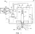
- FIG. 1 schematically shows the configuration of an ion current measurement apparatus 100.
- the ion current measurement apparatus 100 is mounted on a diesel engine vehicle and measures the value of ion current originating from ions generated in a combustion chamber of a diesel engine. Further, the ion current measurement apparatus 100 heats the interior of the combustion chamber. This heating is performed so as to assist the ignition of fuel injected from an injector 459.
- the ion current measurement apparatus 100 includes a glow plug 1 and a control section 50.
- the glow plug 1 is a ceramic glow plug. As shown in FIG. 1 , the glow plug 1 is attached to a cylinder block 45 by screwing an external thread portion of a housing 4 into the cylinder block 45. As a result, the glow plug 1 is attached in a state in which a forward end portion of the glow plug 1 is exposed to a combustion chamber of the cylinder block 45.
- the control section 50 includes an ECU 52, a glow relay 53, a battery 54, and a glow relay 531.
- the glow relay 53 is disposed between the positive terminal of the battery 54 and an external lead wire 233 of the glow plug 1.
- the negative terminal of the battery 54 is connected to the cylinder block 45 through the glow relay 531.
- the glow relay 531 When the glow relay 531 is on, the negative terminal of the battery 54 electrically communicates with the cylinder block 45. Since the potential of the cylinder block 45 is the ground potential, when the glow relay 531 is on, the negative terminal of the battery 54 is grounded.
- the ECU 52 supplies the electrical power of the battery 54 to the glow plug 1 through the external lead wire 233 by turning on the glow relay 53 and the glow relay 531. By this supply of the electrical power, the ECU 52 causes the glow plug 1 to generate heat.
- the ECU 52 controls the heat generation of the glow plug 1 by controlling the ratio between the on time and off time of the glow relay 53.
- the glow relay 531 is always maintained in its on state during a period during which heating is performed, and is turned off when heating is stopped.
- the control section 50 further includes a DC power supply 51, a relay 55, a resistor 521, and a potentiometer 522.
- the relay 55 is disposed between the resistor 521 and an external lead wire 333 of the glow plug 1.
- the relay 55 allows and prohibits the supply of electricity from the DC power supply 51 to the glow plug 1 through switching operation.
- the negative terminal of the DC power supply 51 is connected to the cylinder block 45, whereby the negative terminal of the DC power supply 51 is grounded.
- the resistor 521 is disposed on the positive terminal side of the DC power supply 51.
- the potentiometer 522 measures a voltage (drop voltage) by which the voltage of the DC power supply 51 drops at the resistor 521.
- the ECU 52 measures the ion current value by using these circuit configurations and utilizing the glow plug 1 as a detection section.
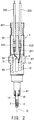
- FIG. 2 is a partially sectioned view of the glow plug 1.
- FIG. 3 is a sectional view of a distal end of the glow plug 1 and its vicinity, and shows the state in which the glow plug 1 is attached to the cylinder block 45. Below, the glow plug 1 will be described with reference to FIGS. 2 and 3 .
- the glow plug 1 includes the housing 4, a heater 10, a terminal portion 23, a terminal portion 31, an internal lead wire 33, an internal lead wire 231, a connection terminal 232, the external lead wire 233, a connection terminal 332, the external lead wire 333, and a rubber bush 421. These members are assembled along the axial line O of the glow plug 1.
- the side of the glow plug 1 where the heater 10 is located will be referred to as the "forward end side,” and the side opposite thereto will be referred to as the "rear end side.”
- the housing 4 includes an outer tube 41, a protection tube 42, and a metallic shell 47.
- the protection tube 42 is an approximately cylindrical member extending along the axial line O and has openings on the forward end side and rear end side thereof. A forward-end-side opening portion of the protection tube 42 is attached to the rear end of the metallic shell 47.
- the rubber bush 421 is inserted into a rear-end-side opening portion of the protection tube 42.
- the rubber bush 421 is a circular columnar member made of rubber.
- the rubber bush 421 inserted into the protection tube 42 seals the space located forward of the rubber bush 421.
- the outer tube 41 is disposed on the forward end side of the protection tube 42.
- the metallic shell 47 has an external thread portion 43. The external thread portion 43 is used to attach the glow plug 1 to the cylinder block 45 of the engine.
- the heater 10 has a generally rod-shaped member which has a hemispherical forward end portion and extends along the axial line O.
- the heater 10 is fixed within the housing 4 via the outer tube 41.
- the outer tube 41 is a ring-shaped member made of metal.
- the heater 10 has an electro-heating element 2, an electrode 3, a substrate 11, and a pair of lead wires 21 and 22.
- the electro-heating element 2, the electrode 3, and the lead wires 21 and 22 are embedded in the substrate 11 and are held.
- the substrate 11 is formed of a ceramic which contains Si 3 N 4 (silicon nitride) as a main component.
- the external lead wires 233 and 333 extend through the rubber bush 421 and reach the interior of the glow plug 1.
- the external lead wire 233 is connected to the terminal portion 23 through the connection terminal 232 and the internal lead wire 231.
- the terminal portion 23 is disposed on the outer circumferential surface of the substrate 11 with a gap formed between the terminal portion 23 and the inner circumferential surface of the housing 4.
- the terminal portion 23 electrically communicates with the housing 4 through the heater 10.
- the housing 4 is fixed to the cylinder block 45 as described above, whereby the housing 4 electrically communicates with the cylinder block 45 which is the ground potential.
- the cylinder block 45 is connected to the negative terminal of the battery 54. Therefore, when the glow relays 53 and 531 are turned on, a closed circuit is formed.
- the lead wire 21 is connected to the terminal portion 23.
- the lead wire 21 extends through the interior of the substrate 11 and is connected to one end of the electro-heating element 2 having a U-like shape.
- the other end of the electro-heating element 2 is connected to the outer tube 41 through the lead wire 22. Therefore, when the glow relays 53 and 531 are turned on, the voltage of the battery 54 is applied to the electro-heating element 2, and a current flows through the electro-heating element 2 embedded in the substrate 11.
- the electro-heating element 2 is formed of a ceramic which is smaller in electrical resistance than the substrate 11. When the voltage of the battery 54 is applied to the electro-heating element 2, a portion of the electro-heating element 2 near the forward end of the heater 10 generates heat.
- the external lead wire 333 is connected to the terminal portion 31 disposed at the rear end of the substrate 11 through the connection terminal 332 and the internal lead wire 33.
- the electrode 3 is connected, at one end thereof, to the terminal portion 31 and extends along the direction of the axial line O within the substrate 11. The other end of the electrode 3 is disposed near the forward end of the electro-heating element 2.
- the electrode 3 is formed of an electrically conductive ceramic and is embedded in the substrate 11 such that the electrode 3 is separated from the electro-heating element 2. Therefore, when the relay 55 is turned on and the DC power supply 51 electrically communicates with the electrode 3, the potential of the electrode 3 becomes higher than the ground potential. When the potential of the electrode 3 rises, the potential of the substrate 11 also becomes higher than the ground potential. When the potential of the substrate 11 is high and ions exist in the combustion chamber, an ion current is produced. This ion current flows through the space between the substrate 11 and the cylinder block 45. Since the negative terminal of the DC power supply 51 is connected to the cylinder block 45, when an ion current is produced, a closed circuit is formed.
- FIG. 4 is a flowchart showing ion current measurement processing. The ion current measurement processing is repeatedly executed by the ECU 52.
- the ECU 52 obtains a drop voltage V 521 at the resistor 521 through use of the potentiometer 522 (step S610). Since the drop voltage V 521 varies due to the influence of the ion current, in step S610, the ECU 52 obtains the value of the drop voltage V 521 over at least a time corresponding to one cycle of the engine.
- FIG. 5 is a graph exemplifies I(t) which shows a time course variation in the current value I obtained as a result of the conversion in step S620.
- the ECU 52 calculates a first substrate resistance R 11 (step S630).
- the first substrate resistance R 11 refers to the electrical resistance of the substrate 11 between the electro-heating element 2 and the electrode 3.
- the substrate 11 is formed of ceramic and has an electrical resistance on the basis of which the substrate 11 is generally classified as an insulator. However, since the electrical resistance of the substrate 11 is naturally finite, when a high voltage is applied to the electrode 3, a slight current flows through the substrate 11. This current flows toward conductors embedded in the substrate 11 and conductors in contact with the substrate 11, and finally flows to the cylinder block 45, which is the ground potential.
- the conductors disposed in the substrate 11 are the electro-heating element 2, the lead wire 21, and the lead wire 22.
- the conductors in contact with the substrate 11 include ions produced within the combustion chamber, in addition to the terminal portion 23, the terminal portion 31, and the outer tube 41.
- the ion current value varies within a time corresponding to one cycle of the engine.
- the currents flowing through other paths hardly vary in such a short period of time. Therefore, the current value obtained as a result of the conversion in step S620 can be divided into a portion corresponding to the ion current and a portion corresponding to the current flowing through the other paths. Specifically, as shown in FIG.
- the minimum value Imin of the current value which is obtained as a result of the conversion in step S620 and which varies with time is the portion corresponding to the current flowing through the other paths, and a value obtained by subtracting the minimum value Imin from the current value is the portion corresponding to the ion current.
- the value obtained by subtracting the minimum value Imin from the current value (I(t) - Imin) will be referred to as a "current value lion(t)."
- the greater part of the current flowing through the other paths flows from the vicinity of the forward end of the electrode 3 to the vicinity of the forward end of the electro-heating element 2. This is because a portion of the substrate 11 having a higher temperature has a smaller electrical resistance as will be described later. Since the electro-heating element 2 generates heat in the vicinity of the forward end thereof as described above, a portion of the substrate 11 near the forward end of the electro-heating element 2 has a higher temperature as compared with other portions.
- the current flowing to the conductors other than the electrode 3 is ignored in the calculation of the first substrate resistance R 11 .
- the electrical resistance of the electro-heating element 2 is smaller than the first substrate resistance R 11 , the electrical resistance of the electro-heating element 2 is ignored in the calculation of the first substrate resistance R 11 .
- the electro-heating element 2 is treated as a conductor.
- the first substrate resistance R 11 is calculated by the following expression (3).
- V 11 represents the potential difference between the electro-heating element 2 and the electrode 3 and V 0 represents the voltage of the DC power supply 51.
- R 11 V 11 / Imin
- V 11 V 0 ⁇ V 521
- the ECU 52 judges whether or not the first substrate resistance R 11 is equal to or less than a predetermined value (step S640).
- a predetermined value the relation between the first substrate resistance R 11 and the highest surface temperature of the substrate 11 will be described.
- the highest surface temperature of the substrate 11 refers to the highest value among the surface temperatures of the substrate 11.
- the substrate 11 has different surface temperatures in different portions thereof, and normally, a portion near the forward end of the electro-heating element 2 has the highest surface temperature.
- FIG. 6 is a graph approximately showing the relation between the first substrate resistance R 11 and the highest surface temperature of the substrate 11.
- This graph is a semilogarithmic graph which shows the first substrate resistance R 11 in logarithm scale. This relation was obtained in advance by an experiment in which the first substrate resistance R 11 was actually measured while the highest surface temperature of the substrate 11 was changed, and is stored in the ECU 52.
- the first substrate resistance R 11 becomes about one-thousandth. Since the substrate 11 has such a characteristic, the highest surface temperature of the substrate 11 has a large influence on the measurement of the ion current value. This is because the substrate 11 acts as a resistor even in a closed circuit formed as a result of generation of the ion current.
- the resistance of the substrate 11 serving as a resistance in this closed circuit will be referred to as a second substrate resistance R 12 .
- Rion(t) represents ion resistance Rion(t).
- the ion resistance Rion(t) is the electrical resistance in the combustion chamber and a variable which varies with the amount of ions generated in the combustion chamber.
- the highest surface temperature of the substrate 11 is a parameter controlled in accordance with the operating state of the engine.
- the highest surface temperature of the substrate 11 is controlled to a target temperature of 1200°C. After that, the target temperature is changed to a temperature lower than 1200°C or heating is stopped.
- the second substrate resistance R 12 depends on the highest surface temperature of the substrate 11. Therefore, as can be understood from the expression (5), the current value lion (t) depends on the highest surface temperature of the substrate 11.
- the current value lion(t) hardly depends on the second substrate resistance R 12 and hardly depends on the highest surface temperature of the substrate 11.
- the expression (6) stands even at the time when the ion resistance Rion(t) is the minimum.
- the "time when the ion resistance Rion(t) is the minimum” is the time when the electrical resistance within the combustion chamber becomes the smallest within one cycle of the engine.
- the predetermined value of the first substrate resistance R 11 in step S640 is the first substrate resistance R 11 at the time when the highest surface temperature is 1200°C (a resistance A in FIG. 6 ; in the following description, denoted as R 11 @1200°C).
- step S640 the ECU 52 judges whether or not the highest surface temperature of the substrate 11 is equal to or higher than 1200°C.
- the ECU 52 obtains the current value lion(t) as the ion current value (step S660).
- the ECU 52 corrects the current value lion(t) (step S650) and obtains the corrected current value as the ion current value (step S660).
- the corrected current value is represented by Ic(t)
- this correction is expressed by the following expression (7).
- Ic t Iion t ⁇ R 12 + Rion t / R 12 @ 1200 ° C + Rion t
- R 12 @1200°C represents the second substrate resistance R 12 at the time when the highest surface temperature of the substrate 11 is 1200°C.
- R 12 @1200°C is very small value as compared with the smallest value of Rion(t). Therefore, the expression (7) can be simplified to obtain the following expression (8).
- Ic t Iion t ⁇ R 12 + Rion t / Rion t
- the second substrate resistance R 12 is calculated by the following expression (11).
- R 12 R 11 ⁇ R 12 @ 1200 ° C / R 11 @ 1200 ° C
- the corrected current Ic(t) is calculated by the expressions (10) and (11).
- the value of R 12 @1200°C/R 11 @1200°C was obtained in advance by an experiment and is stored in the ECU 52.
- the ECU 52 executes steps S670 to S690 for controlling the heating of the combustion chamber.
- the ECU 52 determines a target temperature (step S670).
- the target temperature refers to a target value of the highest surface temperature of the substrate 11.
- the target temperature is determined on the basis of the input value from the water temperature sensor 525, the input value from the engine speed sensor 526, and other values relating to the engine (e.g., the temperature of intake gas).
- the ECU 52 determines a target resistance (step S680).
- the target resistance refers to the first substrate resistance R 11 corresponding to the target temperature determined in step S670. This determination is made on the basis of the relation shown in FIG. 6 .
- the ECU 52 controls the energization of the heater 10 (step S690). Specifically, the ECU 52 controls the ratio between the on time and off time of the glow relay 53 such that the first substrate resistance R 11 approaches the target resistance. After that, the ECU 52 ends the ion current measurement processing.
- the second substrate resistance R 12 strongly depends on the highest surface temperature of the substrate 11 as in the case of the first substrate resistance R 11 . Therefore, the value of ion current which actually flows strongly depends on the highest surface temperature of the substrate 11. However, even when the highest surface temperature of the substrate 11 changes, its influence can be cancelled out, because the measured ion current value is corrected in the present embodiment.
- the electrical resistance of the substrate 11 decreases greatly when its temperature increases, the electrical resistance of a portion of the substrate 11 between the electro-heating element 2 and the electrode 3, which portion has the highest temperature, becomes the dominant factor of the first substrate resistance R 11 .
- the portion of the substrate 11 between the electro-heating element 2 and the electrode 3, which portion has the highest temperature, is located near the forward end of the electro-heating element 2.
- the electrical resistance of a portion of the substrate 11 between the electrode 3 and the surface of the substrate 11, which portion has the highest temperature becomes the dominant factor of the second substrate resistance R 12 .
- the portion of the substrate 11 between the electrode 3 and the surface of the substrate 11, which portion has the highest temperature, is also located near the forward end of the electro-heating element 2.
- the first substrate resistance R 11 and the second substrate resistance R 12 have a strong correlation therebetween. Therefore, the first substrate resistance R 11 is an excellent parameter for estimating the variation of the second substrate resistance R 12 .
- the first substrate resistance R 11 and the second substrate resistance R 12 are parameters which strongly reflect the state of a local portion as described above, they are less likely to be affected by a variation in the production of the glow plug and disturbances.
- the disturbances refer to the cooling water temperature of the engine, the temperature of engine oil, the temperature within the combustion chamber, etc.
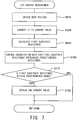
- FIG. 7 is a flowchart showing the ion current measurement processing in the second embodiment. Since steps S610 to S630 are the same as those of the first embodiment, their description will not be repeated.
- the ECU 52 controls the ratio between the on time and off time of the glow relay 53 such that the first substrate resistance R 11 approaches a predetermined resistance (step S700).
- the predetermined resistance is a fixed value determined in advance. This fixed value will be described later.
- the ECU 52 judges whether or not the first substrate resistance R 11 falls within a predetermined range (step S710).
- the predetermined range is determined by adding errors to the above-mentioned predetermined resistance.
- the ECU 52 obtains the current value lion(t) as the ion current value (step S720), and ends the ion current measurement processing.
- step S710 the ECU 52 ends the ion current measurement processing without obtaining the ion current value.
- the processing be executed in the case where the engine can be operated without any problem even when the highest surface temperature of the glow plug 1 is maintained constant.
- the predetermined resistance in step S700 is a resistance corresponding to 1200°C.
- a conceivable alternative method is executing the ion current measurement processing when heating is not requested. Even in the case where the highest surface temperature of the glow plug 1 is low and the ion current value is affected by the second substrate resistance R 12 , correction can be avoided through use of the method of the second embodiment. This is because, when the measurement is performed under the condition that the highest surface temperature of the glow plug 1 falls within the predetermined range as described above, the influence of the second substrate resistance R 12 on the ion current value is approximately constant, and the behavior of the ion current can be monitored without any problem.
- the highest surface temperature is preferably set such that the engine can be operated without any problem.
- the predetermined resistance in step S700 is a resistance corresponding to that highest surface temperature.
- the ion current measurement processing of the second embodiment can accurately estimate the state of combustion within the combustion chamber without correcting the ion current value.
- the method in which the highest surface temperature of the glow plug 1 is maintained at 1200°C as described above can accurately measure the ion current value as having been described in the first embodiment.
- the glow plug 1 and the control section 50 are contained in the ion current measurement apparatus 100.
- the control section 50 may considered as an ion current measurement apparatus, and the ion current measurement apparatus 100 may be considered as an ion current measurement system.
- the material of the substrate may be changed to other ceramics.
- the material may be titanium diboride or a mixture of silicon nitride and titanium diboride.
- the material may be alumina, sialon, or the like.
- a circuit for obtaining the first substrate resistance may be added.
- the circuit may be configured to apply a voltage between the pair of external lead wires and measure the value of current. Since this configuration allows accurate grasping of the voltage applied between the electro-heating element and the electrode, the accuracy in measuring the first substrate resistance improves.
- the highest surface temperature may be estimated from the relation shown in FIG. 6 and the calculated first substrate resistance.
Landscapes
- Engineering & Computer Science (AREA)
- Chemical & Material Sciences (AREA)
- Combustion & Propulsion (AREA)
- Mechanical Engineering (AREA)
- General Engineering & Computer Science (AREA)
- Ignition Installations For Internal Combustion Engines (AREA)
Claims (2)
- Ionenstrommessvorrichtung (100), umfassend einen Erfassungsabschnitt (1) und einen Steuerabschnitt (50);
wobei der Erfassungsabschnitt (1) erste und zweite Leiter (2, 3) und ein Substrat (11) umfasst, das aus Keramik gebildet ist und in dem die ersten und zweiten Leiter (2, 3) separat eingebettet und gehalten werden, wobei ein Ende des zweiten Leiters (3) in der Nähe des vorderen Endes des ersten Leiters (2) angeordnet ist, wobei der der Erfassungsabschnitt (1) für die Befestigung an einem Verbrennungsmotor eingerichtet ist, sodass das Substrat (11) einer Verbrennungskammer des Verbrennungsmotors ausgesetzt ist, worin Ionen infolge der Verbrennung von Kraftstoff erzeugt werden;
wobei der Steuerabschnitt (50) Folgendes umfasst:einen Messabschnitt (52, S610, S620), der dazu eingerichtet ist, einen Stromwert (Iion) zu messen, der als ein Ionenstrom, der von den erzeugten Ionen stammt, durch den zweiten Leiter (3) fließt,einen Erlangungsabschnitt (S630), der dazu eingerichtet ist, einen ersten elektrischen Substrat-Widerstand (Rn) des Substrats (11) zwischen dem ersten Leiter (2) und dem zweiten Leiter (3) beruhend auf einem potentiellen Unterschied zwischen dem ersten Leiter (2) und dem zweiten Leiter (3) und einem elektrischen Strom, der zwischen dem ersten Leiter (2) und dem zweiten Leiter (3) fließt, zu erlangen; undeinen Korrekturabschnitt (S640, S650), der dazu eingerichtet ist, zu beurteilen (S640), ob der erste Substratwiderstand (Rn) größer ist als ein festgelegter Wert, und in dem Fall, in dem der erste Substratwiderstand (R11) größer ist als der festgelegte Wert, wird ein zweiter Substratwiderstand (R12) beruhend auf dem ersten Substratwiderstand (R11) berechnet, wobei der zweite Substratwiderstand (R12) der elektrische Widerstand des Substrats (11) zwischen dem zweiten Leiter (3) und der Verbrennungskammer des Verbrennungsmotors ist, worin Ionen infolge der Verbrennung von Kraftstoff erzeugt werden, und der dazu eingerichtet, den vom Messabschnitt (S610, S620) gemessenen Stromwert (Iion) beruhend auf dem zweiten Substratwiderstand (R12) zu korrigieren. - Ionenstrommessvorrichtung (100) nach Anspruch 1, wobei der erste Leiter (2) ein Heizelement ist, das Wärme erzeugt, wenn ihm Elektrizität zugeführt wird.
Priority Applications (1)
| Application Number | Priority Date | Filing Date | Title |
|---|---|---|---|
| EP17150296.6A EP3171018B1 (de) | 2015-01-16 | 2015-12-24 | Ionenstrommessvorrichtung |
Applications Claiming Priority (1)
| Application Number | Priority Date | Filing Date | Title |
|---|---|---|---|
| JP2015006313A JP6435200B2 (ja) | 2015-01-16 | 2015-01-16 | イオン電流測定装置 |
Related Child Applications (2)
| Application Number | Title | Priority Date | Filing Date |
|---|---|---|---|
| EP17150296.6A Division EP3171018B1 (de) | 2015-01-16 | 2015-12-24 | Ionenstrommessvorrichtung |
| EP17150296.6A Division-Into EP3171018B1 (de) | 2015-01-16 | 2015-12-24 | Ionenstrommessvorrichtung |
Publications (2)
| Publication Number | Publication Date |
|---|---|
| EP3045714A1 EP3045714A1 (de) | 2016-07-20 |
| EP3045714B1 true EP3045714B1 (de) | 2018-02-28 |
Family
ID=55083303
Family Applications (2)
| Application Number | Title | Priority Date | Filing Date |
|---|---|---|---|
| EP15202741.3A Active EP3045714B1 (de) | 2015-01-16 | 2015-12-24 | Ionenstrommessvorrichtung |
| EP17150296.6A Active EP3171018B1 (de) | 2015-01-16 | 2015-12-24 | Ionenstrommessvorrichtung |
Family Applications After (1)
| Application Number | Title | Priority Date | Filing Date |
|---|---|---|---|
| EP17150296.6A Active EP3171018B1 (de) | 2015-01-16 | 2015-12-24 | Ionenstrommessvorrichtung |
Country Status (2)
| Country | Link |
|---|---|
| EP (2) | EP3045714B1 (de) |
| JP (1) | JP6435200B2 (de) |
Family Cites Families (9)
| Publication number | Priority date | Publication date | Assignee | Title |
|---|---|---|---|---|
| DE3742102A1 (de) * | 1987-12-11 | 1989-06-22 | Beru Werk Ruprecht Gmbh Co A | Verfahren zum regeln eines heizelementes und heizelement zur durchfuehrung dieses verfahrens |
| JP3605965B2 (ja) | 1996-09-12 | 2004-12-22 | 株式会社デンソー | グロープラグ |
| JPH1144282A (ja) * | 1997-07-28 | 1999-02-16 | Denso Corp | イオン電流検出装置 |
| JP2001336468A (ja) * | 2000-03-22 | 2001-12-07 | Ngk Spark Plug Co Ltd | グロープラグ制御装置、グロープラグ、及びエンジンの燃焼室内のイオン検出方法 |
| JP2001295744A (ja) * | 2000-04-12 | 2001-10-26 | Ngk Spark Plug Co Ltd | イオン電流検出装置 |
| JP4094205B2 (ja) * | 2000-05-23 | 2008-06-04 | 日本特殊陶業株式会社 | セラミックヒータ又はグロープラグの特性測定方法 |
| JP4109516B2 (ja) * | 2002-08-29 | 2008-07-02 | 日本特殊陶業株式会社 | イオン電流検知装置 |
| JP4346343B2 (ja) * | 2003-04-30 | 2009-10-21 | 日本特殊陶業株式会社 | イオン電流検知装置 |
| US20050098136A1 (en) * | 2003-11-10 | 2005-05-12 | Visteon Global Technologies, Inc. | Architecture to integrate ionization detection electronics into and near a diesel glow plug |
-
2015
- 2015-01-16 JP JP2015006313A patent/JP6435200B2/ja active Active
- 2015-12-24 EP EP15202741.3A patent/EP3045714B1/de active Active
- 2015-12-24 EP EP17150296.6A patent/EP3171018B1/de active Active
Non-Patent Citations (1)
| Title |
|---|
| None * |
Also Published As
| Publication number | Publication date |
|---|---|
| EP3171018A1 (de) | 2017-05-24 |
| EP3045714A1 (de) | 2016-07-20 |
| JP2016133004A (ja) | 2016-07-25 |
| EP3171018B1 (de) | 2018-03-14 |
| JP6435200B2 (ja) | 2018-12-05 |
Similar Documents
| Publication | Publication Date | Title |
|---|---|---|
| US8847118B2 (en) | Energization control apparatus for glow plug | |
| US9074575B2 (en) | Energization control apparatus for glow plug | |
| US8217310B2 (en) | Glow plug electrification control apparatus and glow plug electrification control system | |
| US6414273B1 (en) | Glow plug control apparatus, glow plug, and method of detecting ions in engine combustion chamber | |
| JP5465263B2 (ja) | NOxセンサ制御装置 | |
| EP1505298B1 (de) | Steuerung für glühkerze und glühkerze | |
| JP5851366B2 (ja) | センサ制御装置及びセンサ制御システム | |
| US9255564B2 (en) | Glow plug tip temperature estimating method and glow plug drive control device | |
| KR101188072B1 (ko) | 글로 플러그의 통전 제어장치 및 발열 시스템 | |
| EP3046395B1 (de) | Heizvorrichtung, temperaturschätzungsvorrichtung und heizungsregelungsvorrichtung | |
| EP3045714B1 (de) | Ionenstrommessvorrichtung | |
| US10436695B2 (en) | Particulate matter detection system | |
| JP4723174B2 (ja) | グロープラグ通電制御装置及びグロープラグ通電制御方法 | |
| EP3096000A2 (de) | Heizvorrichtung, heizzustandsschätzvorrichtung und heizzustandsschätzverfahren | |
| JP6736254B2 (ja) | グロープラグ | |
| US8228659B2 (en) | Glow plug electrification control apparatus and glow plug electrification control system | |
| JP5653517B2 (ja) | グロープラグ及びグロープラグ新品判別方法並びにグロープラグ駆動制御装置 | |
| JP2009121401A (ja) | 内燃機関の排気温度推定装置に関する。 | |
| JP6667327B2 (ja) | 加熱装置及び温度推定装置 | |
| JPH1144282A (ja) | イオン電流検出装置 | |
| JP5537280B2 (ja) | グロープラグの通電制御装置 | |
| JP2001295744A (ja) | イオン電流検出装置 |
Legal Events
| Date | Code | Title | Description |
|---|---|---|---|
| PUAI | Public reference made under article 153(3) epc to a published international application that has entered the european phase |
Free format text: ORIGINAL CODE: 0009012 |
|
| AK | Designated contracting states |
Kind code of ref document: A1 Designated state(s): AL AT BE BG CH CY CZ DE DK EE ES FI FR GB GR HR HU IE IS IT LI LT LU LV MC MK MT NL NO PL PT RO RS SE SI SK SM TR |
|
| AX | Request for extension of the european patent |
Extension state: BA ME |
|
| STAA | Information on the status of an ep patent application or granted ep patent |
Free format text: STATUS: REQUEST FOR EXAMINATION WAS MADE |
|
| 17P | Request for examination filed |
Effective date: 20161220 |
|
| RBV | Designated contracting states (corrected) |
Designated state(s): AL AT BE BG CH CY CZ DE DK EE ES FI FR GB GR HR HU IE IS IT LI LT LU LV MC MK MT NL NO PL PT RO RS SE SI SK SM TR |
|
| STAA | Information on the status of an ep patent application or granted ep patent |
Free format text: STATUS: EXAMINATION IS IN PROGRESS |
|
| 17Q | First examination report despatched |
Effective date: 20170421 |
|
| RIC1 | Information provided on ipc code assigned before grant |
Ipc: F02P 19/02 20060101AFI20170928BHEP Ipc: F23Q 7/00 20060101ALI20170928BHEP Ipc: F02D 35/02 20060101ALN20170928BHEP |
|
| GRAP | Despatch of communication of intention to grant a patent |
Free format text: ORIGINAL CODE: EPIDOSNIGR1 |
|
| STAA | Information on the status of an ep patent application or granted ep patent |
Free format text: STATUS: GRANT OF PATENT IS INTENDED |
|
| INTG | Intention to grant announced |
Effective date: 20171109 |
|
| GRAS | Grant fee paid |
Free format text: ORIGINAL CODE: EPIDOSNIGR3 |
|
| GRAA | (expected) grant |
Free format text: ORIGINAL CODE: 0009210 |
|
| STAA | Information on the status of an ep patent application or granted ep patent |
Free format text: STATUS: THE PATENT HAS BEEN GRANTED |
|
| GRAT | Correction requested after decision to grant or after decision to maintain patent in amended form |
Free format text: ORIGINAL CODE: EPIDOSNCDEC |
|
| AK | Designated contracting states |
Kind code of ref document: B1 Designated state(s): AL AT BE BG CH CY CZ DE DK EE ES FI FR GB GR HR HU IE IS IT LI LT LU LV MC MK MT NL NO PL PT RO RS SE SI SK SM TR |
|
| REG | Reference to a national code |
Ref country code: GB Ref legal event code: FG4D Ref country code: CH Ref legal event code: EP |
|
| REG | Reference to a national code |
Ref country code: AT Ref legal event code: REF Ref document number: 974441 Country of ref document: AT Kind code of ref document: T Effective date: 20180315 |
|
| RAP2 | Party data changed (patent owner data changed or rights of a patent transferred) |
Owner name: NGK SPARK PLUG CO., LTD. |
|
| REG | Reference to a national code |
Ref country code: IE Ref legal event code: FG4D |
|
| REG | Reference to a national code |
Ref country code: DE Ref legal event code: R096 Ref document number: 602015008326 Country of ref document: DE |
|
| REG | Reference to a national code |
Ref country code: DE Ref legal event code: R081 Ref document number: 602015008326 Country of ref document: DE Owner name: NKG SPARK PLUG CO., LTD., NAGOYA, JP Free format text: FORMER OWNER: NGK SPARK PLUG COMPANY LIMITED, NAGOYA, AICHI, JP |
|
| REG | Reference to a national code |
Ref country code: NL Ref legal event code: MP Effective date: 20180228 |
|
| REG | Reference to a national code |
Ref country code: LT Ref legal event code: MG4D |
|
| REG | Reference to a national code |
Ref country code: AT Ref legal event code: MK05 Ref document number: 974441 Country of ref document: AT Kind code of ref document: T Effective date: 20180228 |
|
| PG25 | Lapsed in a contracting state [announced via postgrant information from national office to epo] |
Ref country code: ES Free format text: LAPSE BECAUSE OF FAILURE TO SUBMIT A TRANSLATION OF THE DESCRIPTION OR TO PAY THE FEE WITHIN THE PRESCRIBED TIME-LIMIT Effective date: 20180228 Ref country code: NL Free format text: LAPSE BECAUSE OF FAILURE TO SUBMIT A TRANSLATION OF THE DESCRIPTION OR TO PAY THE FEE WITHIN THE PRESCRIBED TIME-LIMIT Effective date: 20180228 Ref country code: FI Free format text: LAPSE BECAUSE OF FAILURE TO SUBMIT A TRANSLATION OF THE DESCRIPTION OR TO PAY THE FEE WITHIN THE PRESCRIBED TIME-LIMIT Effective date: 20180228 Ref country code: NO Free format text: LAPSE BECAUSE OF FAILURE TO SUBMIT A TRANSLATION OF THE DESCRIPTION OR TO PAY THE FEE WITHIN THE PRESCRIBED TIME-LIMIT Effective date: 20180528 Ref country code: HR Free format text: LAPSE BECAUSE OF FAILURE TO SUBMIT A TRANSLATION OF THE DESCRIPTION OR TO PAY THE FEE WITHIN THE PRESCRIBED TIME-LIMIT Effective date: 20180228 Ref country code: LT Free format text: LAPSE BECAUSE OF FAILURE TO SUBMIT A TRANSLATION OF THE DESCRIPTION OR TO PAY THE FEE WITHIN THE PRESCRIBED TIME-LIMIT Effective date: 20180228 Ref country code: CY Free format text: LAPSE BECAUSE OF FAILURE TO SUBMIT A TRANSLATION OF THE DESCRIPTION OR TO PAY THE FEE WITHIN THE PRESCRIBED TIME-LIMIT Effective date: 20180228 |
|
| PG25 | Lapsed in a contracting state [announced via postgrant information from national office to epo] |
Ref country code: GR Free format text: LAPSE BECAUSE OF FAILURE TO SUBMIT A TRANSLATION OF THE DESCRIPTION OR TO PAY THE FEE WITHIN THE PRESCRIBED TIME-LIMIT Effective date: 20180529 Ref country code: BG Free format text: LAPSE BECAUSE OF FAILURE TO SUBMIT A TRANSLATION OF THE DESCRIPTION OR TO PAY THE FEE WITHIN THE PRESCRIBED TIME-LIMIT Effective date: 20180528 Ref country code: LV Free format text: LAPSE BECAUSE OF FAILURE TO SUBMIT A TRANSLATION OF THE DESCRIPTION OR TO PAY THE FEE WITHIN THE PRESCRIBED TIME-LIMIT Effective date: 20180228 Ref country code: SE Free format text: LAPSE BECAUSE OF FAILURE TO SUBMIT A TRANSLATION OF THE DESCRIPTION OR TO PAY THE FEE WITHIN THE PRESCRIBED TIME-LIMIT Effective date: 20180228 Ref country code: RS Free format text: LAPSE BECAUSE OF FAILURE TO SUBMIT A TRANSLATION OF THE DESCRIPTION OR TO PAY THE FEE WITHIN THE PRESCRIBED TIME-LIMIT Effective date: 20180228 Ref country code: AT Free format text: LAPSE BECAUSE OF FAILURE TO SUBMIT A TRANSLATION OF THE DESCRIPTION OR TO PAY THE FEE WITHIN THE PRESCRIBED TIME-LIMIT Effective date: 20180228 |
|
| PG25 | Lapsed in a contracting state [announced via postgrant information from national office to epo] |
Ref country code: PL Free format text: LAPSE BECAUSE OF FAILURE TO SUBMIT A TRANSLATION OF THE DESCRIPTION OR TO PAY THE FEE WITHIN THE PRESCRIBED TIME-LIMIT Effective date: 20180228 Ref country code: EE Free format text: LAPSE BECAUSE OF FAILURE TO SUBMIT A TRANSLATION OF THE DESCRIPTION OR TO PAY THE FEE WITHIN THE PRESCRIBED TIME-LIMIT Effective date: 20180228 Ref country code: RO Free format text: LAPSE BECAUSE OF FAILURE TO SUBMIT A TRANSLATION OF THE DESCRIPTION OR TO PAY THE FEE WITHIN THE PRESCRIBED TIME-LIMIT Effective date: 20180228 Ref country code: AL Free format text: LAPSE BECAUSE OF FAILURE TO SUBMIT A TRANSLATION OF THE DESCRIPTION OR TO PAY THE FEE WITHIN THE PRESCRIBED TIME-LIMIT Effective date: 20180228 |
|
| REG | Reference to a national code |
Ref country code: DE Ref legal event code: R097 Ref document number: 602015008326 Country of ref document: DE |
|
| PG25 | Lapsed in a contracting state [announced via postgrant information from national office to epo] |
Ref country code: SM Free format text: LAPSE BECAUSE OF FAILURE TO SUBMIT A TRANSLATION OF THE DESCRIPTION OR TO PAY THE FEE WITHIN THE PRESCRIBED TIME-LIMIT Effective date: 20180228 Ref country code: CZ Free format text: LAPSE BECAUSE OF FAILURE TO SUBMIT A TRANSLATION OF THE DESCRIPTION OR TO PAY THE FEE WITHIN THE PRESCRIBED TIME-LIMIT Effective date: 20180228 Ref country code: DK Free format text: LAPSE BECAUSE OF FAILURE TO SUBMIT A TRANSLATION OF THE DESCRIPTION OR TO PAY THE FEE WITHIN THE PRESCRIBED TIME-LIMIT Effective date: 20180228 Ref country code: SK Free format text: LAPSE BECAUSE OF FAILURE TO SUBMIT A TRANSLATION OF THE DESCRIPTION OR TO PAY THE FEE WITHIN THE PRESCRIBED TIME-LIMIT Effective date: 20180228 |
|
| PLBE | No opposition filed within time limit |
Free format text: ORIGINAL CODE: 0009261 |
|
| STAA | Information on the status of an ep patent application or granted ep patent |
Free format text: STATUS: NO OPPOSITION FILED WITHIN TIME LIMIT |
|
| 26N | No opposition filed |
Effective date: 20181129 |
|
| PG25 | Lapsed in a contracting state [announced via postgrant information from national office to epo] |
Ref country code: SI Free format text: LAPSE BECAUSE OF FAILURE TO SUBMIT A TRANSLATION OF THE DESCRIPTION OR TO PAY THE FEE WITHIN THE PRESCRIBED TIME-LIMIT Effective date: 20180228 |
|
| REG | Reference to a national code |
Ref country code: CH Ref legal event code: PL |
|
| PG25 | Lapsed in a contracting state [announced via postgrant information from national office to epo] |
Ref country code: MC Free format text: LAPSE BECAUSE OF FAILURE TO SUBMIT A TRANSLATION OF THE DESCRIPTION OR TO PAY THE FEE WITHIN THE PRESCRIBED TIME-LIMIT Effective date: 20180228 Ref country code: LU Free format text: LAPSE BECAUSE OF NON-PAYMENT OF DUE FEES Effective date: 20181224 |
|
| REG | Reference to a national code |
Ref country code: IE Ref legal event code: MM4A |
|
| REG | Reference to a national code |
Ref country code: BE Ref legal event code: MM Effective date: 20181231 |
|
| PG25 | Lapsed in a contracting state [announced via postgrant information from national office to epo] |
Ref country code: IE Free format text: LAPSE BECAUSE OF NON-PAYMENT OF DUE FEES Effective date: 20181224 |
|
| PG25 | Lapsed in a contracting state [announced via postgrant information from national office to epo] |
Ref country code: BE Free format text: LAPSE BECAUSE OF NON-PAYMENT OF DUE FEES Effective date: 20181231 |
|
| PG25 | Lapsed in a contracting state [announced via postgrant information from national office to epo] |
Ref country code: LI Free format text: LAPSE BECAUSE OF NON-PAYMENT OF DUE FEES Effective date: 20181231 Ref country code: CH Free format text: LAPSE BECAUSE OF NON-PAYMENT OF DUE FEES Effective date: 20181231 |
|
| PG25 | Lapsed in a contracting state [announced via postgrant information from national office to epo] |
Ref country code: MT Free format text: LAPSE BECAUSE OF NON-PAYMENT OF DUE FEES Effective date: 20181224 |
|
| PGFP | Annual fee paid to national office [announced via postgrant information from national office to epo] |
Ref country code: IT Payment date: 20191209 Year of fee payment: 5 Ref country code: FR Payment date: 20191115 Year of fee payment: 5 |
|
| PG25 | Lapsed in a contracting state [announced via postgrant information from national office to epo] |
Ref country code: TR Free format text: LAPSE BECAUSE OF FAILURE TO SUBMIT A TRANSLATION OF THE DESCRIPTION OR TO PAY THE FEE WITHIN THE PRESCRIBED TIME-LIMIT Effective date: 20180228 |
|
| PG25 | Lapsed in a contracting state [announced via postgrant information from national office to epo] |
Ref country code: PT Free format text: LAPSE BECAUSE OF FAILURE TO SUBMIT A TRANSLATION OF THE DESCRIPTION OR TO PAY THE FEE WITHIN THE PRESCRIBED TIME-LIMIT Effective date: 20180228 |
|
| PG25 | Lapsed in a contracting state [announced via postgrant information from national office to epo] |
Ref country code: HU Free format text: LAPSE BECAUSE OF FAILURE TO SUBMIT A TRANSLATION OF THE DESCRIPTION OR TO PAY THE FEE WITHIN THE PRESCRIBED TIME-LIMIT; INVALID AB INITIO Effective date: 20151224 Ref country code: MK Free format text: LAPSE BECAUSE OF NON-PAYMENT OF DUE FEES Effective date: 20180228 |
|
| PG25 | Lapsed in a contracting state [announced via postgrant information from national office to epo] |
Ref country code: IS Free format text: LAPSE BECAUSE OF FAILURE TO SUBMIT A TRANSLATION OF THE DESCRIPTION OR TO PAY THE FEE WITHIN THE PRESCRIBED TIME-LIMIT Effective date: 20180628 |
|
| GBPC | Gb: european patent ceased through non-payment of renewal fee |
Effective date: 20191224 |
|
| PG25 | Lapsed in a contracting state [announced via postgrant information from national office to epo] |
Ref country code: GB Free format text: LAPSE BECAUSE OF NON-PAYMENT OF DUE FEES Effective date: 20191224 |
|
| PG25 | Lapsed in a contracting state [announced via postgrant information from national office to epo] |
Ref country code: FR Free format text: LAPSE BECAUSE OF NON-PAYMENT OF DUE FEES Effective date: 20201231 Ref country code: IT Free format text: LAPSE BECAUSE OF NON-PAYMENT OF DUE FEES Effective date: 20201224 |
|
| REG | Reference to a national code |
Ref country code: DE Ref legal event code: R081 Ref document number: 602015008326 Country of ref document: DE Owner name: NITERRA CO., LTD., NAGOYA-SHI, JP Free format text: FORMER OWNER: NKG SPARK PLUG CO., LTD., NAGOYA, AICHI, JP |
|
| PGFP | Annual fee paid to national office [announced via postgrant information from national office to epo] |
Ref country code: DE Payment date: 20251028 Year of fee payment: 11 |