EP3096000A2 - Heizvorrichtung, heizzustandsschätzvorrichtung und heizzustandsschätzverfahren - Google Patents
Heizvorrichtung, heizzustandsschätzvorrichtung und heizzustandsschätzverfahren Download PDFInfo
- Publication number
- EP3096000A2 EP3096000A2 EP16164940.5A EP16164940A EP3096000A2 EP 3096000 A2 EP3096000 A2 EP 3096000A2 EP 16164940 A EP16164940 A EP 16164940A EP 3096000 A2 EP3096000 A2 EP 3096000A2
- Authority
- EP
- European Patent Office
- Prior art keywords
- heater
- heating unit
- base
- unit
- state
- Prior art date
- Legal status (The legal status is an assumption and is not a legal conclusion. Google has not performed a legal analysis and makes no representation as to the accuracy of the status listed.)
- Withdrawn
Links
Images



Classifications
-
- F—MECHANICAL ENGINEERING; LIGHTING; HEATING; WEAPONS; BLASTING
- F02—COMBUSTION ENGINES; HOT-GAS OR COMBUSTION-PRODUCT ENGINE PLANTS
- F02P—IGNITION, OTHER THAN COMPRESSION IGNITION, FOR INTERNAL-COMBUSTION ENGINES; TESTING OF IGNITION TIMING IN COMPRESSION-IGNITION ENGINES
- F02P19/00—Incandescent ignition, e.g. during starting of internal combustion engines; Combination of incandescent and spark ignition
- F02P19/02—Incandescent ignition, e.g. during starting of internal combustion engines; Combination of incandescent and spark ignition electric, e.g. layout of circuits of apparatus having glowing plugs
-
- F—MECHANICAL ENGINEERING; LIGHTING; HEATING; WEAPONS; BLASTING
- F23—COMBUSTION APPARATUS; COMBUSTION PROCESSES
- F23Q—IGNITION; EXTINGUISHING-DEVICES
- F23Q7/00—Incandescent ignition; Igniters using electrically-produced heat, e.g. lighters for cigarettes; Electrically-heated glowing plugs
- F23Q7/001—Glowing plugs for internal-combustion engines
Definitions
- the present invention relates to estimation of the state of a heater.
- a glow plug includes a heater that includes a heating unit and a base in which the heating unit is held.
- the glow plug is used as an auxiliary heat source for a compression ignition type internal combustion engine (e.g., a diesel engine or the like).
- a compression ignition type internal combustion engine e.g., a diesel engine or the like.
- a crack may occur in the heating unit. This abnormality causes an increase in the resistance of the heating unit, and the temperature of the heater becomes less likely to increase. As a result, startability of the engine may be degraded, or a soot component in exhaust gas may increase.
- Patent Document 1 discloses a technique of detecting abnormality of a heating unit on the basis of an increase in the resistance of the heating unit.
- Patent Document 1 Japanese Patent No. 4780056
- the resistance of the heating unit in the case where abnormality occurs in the heating unit increases only slightly as compared to that in the normal state. Therefore, in the technique of Patent Document 1, abnormality of the heating unit should be detected on the basis of the very small change in the resistance of the heating unit. Accordingly, the detection accuracy is poor, and slight abnormality of the heating unit cannot be detected. Thus, a technique for improving the accuracy of detecting abnormality of the heating unit has been demanded. Meanwhile, since the base is exposed to the atmosphere in a combustion chamber or the like, the base may be worn due to corrosion caused by chemical reaction with components contained in fuel and oil, or erosion caused by high-pressure fuel injection and swirl in the engine.
- the present invention has been made to solve the above-described problem, and can be embodied in the following modes.
- the present invention can be realized in various modes.
- the present invention can be realized as a heater state estimating device, a heater state estimating method, a glow plug abnormality detecting device, and the like.
- FIG. 1 is an explanatory view showing the schematic configuration of a heating device which is one embodiment of the present invention.
- the heating device 100 according to the present embodiment is mounted on a diesel engine vehicle, and heats a combustion chamber 610 of the diesel engine 600 to assist ignition of fuel injected from an injector 459 of the diesel engine 600.
- the heating device 100 includes a glow plug 1 and a controller 50.
- the glow plug 1 is a ceramic glow plug.
- the glow plug 1 is mounted to a cylinder head 620 of the diesel engine 600 with a front end portion thereof being exposed in the combustion chamber 610. The configuration of the glow plug 1 will be described later in detail.
- the controller 50 includes an electronic control unit (ECU) 52, a first glow relay 53, a battery 54, a second glow relay 531, a relay 55, a DC power supply 51, a resistor 521, and a potentiometer 522.
- the ECU 52 is configured as a microcomputer including a CPU, a RAM, and a ROM, and controls heat generation of the glow plug 1.
- the ECU 52 includes a resistance detecting unit 60 and a state estimating unit 70.
- the resistance detecting unit 60 detects an electric resistance of a base described later.
- the state estimating unit 70 estimates the state of a heater on the basis of the electric resistance of the base in a heater state estimating process described later.
- the first glow relay 53 is disposed between a positive electrode of the battery 54 and an external lead wire 233 of the glow plug 1.
- a negative electrode of the battery 54 is connected to the cylinder head 620 via the second glow relay 531, and is electrically connected to the cylinder head 620 when the second glow relay 531 is in its on state. Since the potential of the cylinder head 620 is the ground potential, the negative electrode of the battery 54 is grounded when the second glow relay 531 is in the on state.
- the ECU 52 turns on the first glow relay 53 and the second glow relay 531 to supply power from the battery 54 to the glow plug 1 via the external lead wire 233, and thereby causes the glow plug 1 to generate heat.
- the ECU 52 controls the ratio between the on time and the off time of the first glow relay 53 to control the heat generation of the glow plug 1.
- the second glow relay 531 is constantly in the on state while heating is executed, and is turned off when heating is stopped.
- the relay 55 is disposed between the resistor 521 and an external lead wire 333 of the glow plug 1.
- the relay 55 turns on and off power supply from the DC power supply 51 to the glow plug 1.
- a negative electrode of the DC power supply 51 is grounded by being connected to the cylinder head 620.
- the resistor 521 is connected to a positive electrode of the DC power supply 51.
- the potentiometer 522 measures a voltage value that drops (voltage drop) in the resistor 521.
- the ECU 52 is electrically connected to an external water temperature sensor 525 and an external rotation speed sensor 526.
- the water temperature sensor 525 measures the temperature of engine cooling water.
- the rotation speed sensor 526 measures the rotation speed of the engine. The ECU 52 obtains these values and uses them for control of heat generation of the glow plug 1.
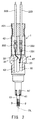
- FIG. 2 is a partial cross-sectional view showing the configuration of the glow plug 1 in detail.
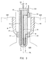
- FIG. 3 is an enlarged cross-sectional view showing the structure of a front end portion of the glow plug 1.
- FIG. 3 shows the state where the glow plug 1 is mounted to the cylinder head 620.
- an axis OL of the glow plug 1 is shown by an alternate long and short dash line.
- a side where a later-described heater 10 is disposed is referred to as a "front side”
- a side where the external lead wires 233 and 333 are disposed is referred to as a "rear side”.
- the glow plug 1 includes a housing 4, a rubber bush 421, a heater 10, two terminal portions 23 and 31, two external lead wires 233 and 333, and two internal lead wires 33 and 231.
- the housing 4 forms an outline of the glow plug 1, and includes a metallic shell 47, a protection tube 42, and a sheath 41.
- the metallic shell 47 has a substantially tubular appearance extending along the axis OL, and is located on the front side in the housing 4.
- an external thread portion 43 is formed on an outer peripheral surface of the metallic shell 47 on the front side.
- the external thread portion 43 is screwed into an internal thread portion (not shown) formed on the cylinder head 620 of the diesel engine 600.
- the protection tube 42 has a substantially tubular appearance extending along the axis OL, and is located on the rear side in the housing 4.
- the protection tube 42 has opening portions on the front side and the rear side.
- the front-side opening portion of the protection tube 42 is attached to a rear end portion of the metallic shell 47.
- the rearside opening portion of the protection tube 42 is closed by the rubber bush 421.
- the rubber bush 421 has a substantially cylindrical appearance, and is made of a rubber.
- the rubber bush 421 inserted in the protection tube 42 seals a space on the front side relative to the rubber bush 421.
- the sheath 41 has a ring-shaped appearance, is made of a metal, and is disposed on the front end portion of the metallic shell 47.
- the heater 10 has a hemispheric front end portion, and has a substantially rod-like appearance extending along the axis OL.
- the heater 10 is fixed by the sheath 41 so that a rear end portion thereof is housed in the housing 4 and a front end portion thereof is exposed from the housing 4.
- the heater 10 includes a base 11, an energization heating unit 2, an electrode 3, and two lead wires 21 and 22.
- the base 11 holds the energization heating unit 2 and the electrode 3 so that the energization heating unit 2 and the electrode 3 are buried in the base 11 so as to be isolated from each other.
- the base 11 is made of a ceramic containing silicon nitride (Si 3 N 4 ) as a principal component, and has high insulating property.
- the energization heating unit 2 has a U-shaped appearance, and is buried in the front end portion of the heater 10.
- the energization heating unit 2 is made of a silicon nitride-based ceramic to which electrical conductivity is given, and generates heat by energization.
- the electric resistance of the energization heating unit 2 is smaller than the electric resistance of the base 11.
- the lead wires 21 and 22 are connected, respectively.
- the lead wires 21 and 22 buried in the base 11.
- One end of the energization heating unit 2 is connected to the terminal portion 23 via the lead wire 21.
- the other end of the energization heating unit 2 is connected to the sheath 41 via the lead wire 22.
- the electrode 3 has a rod-shaped appearance extending in the direction along the axis OL. One end of the electrode 3 is connected to the terminal portion 31, and the other end thereof is disposed near the front end of the energization heating unit 2.
- the electrode 3 is used to detect the electric resistance of the base 11, and is made of an electrically conductive ceramic.
- the terminal portion 23 is disposed on an outer peripheral surface of the base 11 with a gap between the terminal portion 23 and an inner peripheral surface of the housing 4.
- the terminal portion 23 electrically communicates with the housing 4 via the heater 10 and the sheath 41.
- the terminal portion 31 is disposed in contact with the rear end portion of the heater 10.
- the external lead wires 233 and 333 penetrate the rubber bush 421, and communicate with the inside of the glow plug 1.
- the external lead wire 233 is connected to the terminal portion 23 via a connection terminal 232 and the internal lead wire 231.
- the external lead wire 333 is connected to the terminal portion 31 via a connection terminal 332 and the internal lead wire 33.
- the energization heating unit 2 corresponds to a subordinate concept of a heating unit in claims
- the electrode 3 corresponds to a subordinate concept of an electric conductor in claims
- the controller 50 corresponds to a subordinate concept of an energization unit in claims
- the resistance detecting unit 60 corresponds to a subordinate concept of a detection unit in claims
- the state estimating unit 70 corresponds to a subordinate concept of an estimation unit in claims.
- the housing 4 is mounted on the cylinder head 620 as shown in FIG. 1 , and therefore electrically communicates with the cylinder head 620 at the ground potential. Therefore, when the glow relays 53 and 531 are turned on, a closed circuit is formed, and a voltage from the battery 54 is applied to the energization heating unit 2. Then, a current flows in the energization heating unit 2, and the heater 10 is heated. When the relay 55 is turned on and the DC power supply 51 and the electrode 3 electrically communicate with each other, a potential difference occurs between the electrode 3 and the energization heating unit 2.
- the electric resistance of the base 11 (hereinafter also referred to as "base resistance R 11 ") is detected on the basis of the potential difference.
- the base resistance R 11 means the electric resistance of the base 11 between the energization heating unit 2 and the electrode 3.
- the base 11 is made of a ceramic having high insulating property, and therefore has high electric resistance. However, since the electric resistance of the base 11 is finite, when a high voltage is applied to the electrode 3, a small amount of current flows in the base 11. This current flows through the electric conductors embedded in the base 11 and the electric conductors in contact with the base 11, and finally flows to the cylinder head 620.
- the electric conductors embedded in the base 11 correspond to the energization heating unit 2 and the lead wires 21 and 22.
- the electric conductors in contact with the base 11 correspond to the terminal portions 23 and 31, and the sheath 41.
- the energization heating unit 2 generates heat in the state where it is embedded in the front end portion of the heater 10. Therefore, the temperature of the base 11 on the front side, adjacent to the energization heating unit 2, is more likely to increase as compared to the temperature of the base 11 on the rear side.
- insulating ceramics have the following properties. That is, the higher the temperature of an insulating ceramic is, the more the electric resistance thereof decreases, and more current flows therethrough. The lower the temperature of the insulating ceramic is, the more the electric resistance thereof increases, and less current flows therethrough. Therefore, a greater part of the current flowing in the base 11 flows from near the front end of the electrode 3 to near the front end of the energization heating unit 2.
- the energization heating unit 2 is treated as an electric conductor in the present embodiment.
- the base resistance R 11 is calculated by the following formula (5).
- V 11 represents a potential difference between the energization heating unit 2 and the electrode 3
- I represents a current that flows in the resistor 521
- V 0 represents a voltage of the DC power supply 51
- V 521 represents voltage drop in the resistor 521
- R 521 represents an electric resistance of the resistor 521.
- R 11 V 11 / I
- Formulae (2) and (3) are substituted into formula (1) to obtain formula (4).
- R 11 V 0 ⁇ V 521 / V 521 / R 521 Since V 521 «V 0 in the present embodiment, formula (4) is transformed to obtain formula (5).
- R 11 V 0 ⁇ R 521 / V 521
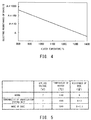
- FIG. 4 is a graph showing the relationship between the base resistance R 11 and the temperature of the heater 10.
- the vertical axis indicates the base resistance R 11 ( ⁇ ) represented as a logarithm to a certain value A, and the horizontal axis indicates the temperature (°C) of the heater 10.
- the certain value A 10 k ⁇ or the like may be adopted.
- the temperature of the heater 10 means the maximum value of the surface temperature of the base 11.
- the surface temperature of the base 11 varies depending on positions in the base 11. Usually, a portion near the front end of the energization heating unit 2 has the maximum temperature value.
- the base resistance R 11 decreases with increase in the temperature of the heater 10, and increases with decrease in the temperature of the heater 10.
- the electric resistance of the energization heating unit 2 increases, and the energization heating unit 2 may be broken in some cases. If the energization heating unit 2 is energized so as to significantly exceed the heat-resistant temperature thereof, atoms of the energization heating unit 2 are diffused due to migration effect, and the energization heating unit 2 is made porous, resulting in increase in the electric resistance of the energization heating unit 2. If a voltage is applied to the energization heating unit 2 under the situation that such abnormality occurs, since the temperature of the energization heating unit 2 is less likely to increase, the temperature of the heater 10 is lower than that in the normal state. Therefore, based on the relationship shown in FIG. 4 , the base resistance R 11 increases more than that in the normal state.
- the temperature of the heater 10 is likely to increase due to reduction in the diameter of the base 11, and becomes higher than that in the normal state. Therefore, based on the relationship shown in FIG. 4 , the base resistance R 11 decreases more than that in the normal state.
- FIG. 5 is an explanatory view showing examples of the base resistance R 11 depending on different states of the heater 10.
- a reference resistance value of the base resistance R 11 of the heater 10 in the normal state is B( ⁇ )
- the base resistance R 11 of the heater 10 having abnormality of the energization heating unit 2 and the base resistance R 11 of the heater 10 having the worn base 11 are represented as ratios to B.
- the base resistances R 11 detected when a constant voltage (7 V) is applied to the energization heating unit 2 are shown together with the respective temperatures of the heater 10.
- the temperature of the heater 10 in the case where the energization heating unit 2 has abnormality is lower than that in the normal state. Therefore, the base resistance R 11 increases more than that in the normal state.
- the temperature of the heater 10 in the case where the base 11 is worn is higher than that in the normal state. Therefore, the base resistance R 11 decreases more than that in the normal case.
- the heater state estimating process described later is executed, whereby the state of the heater 10 such as abnormality of the energization heating unit 2 and wear of the base 11 can be estimated based on the base resistance R 11 .
- FIG. 6 is a flowchart showing the procedure of the heater state estimating process.
- the heater state estimating process is executed when, at start-up of the diesel engine 600, a predetermined voltage is applied to the energization heating unit 2 to energize the glow plug 1, and thereby the diesel engine 600 enters its idle state.
- the ECU 52 obtains the voltage drop V 521 in the resistor 521 by using the potentiometer 522 (step S105).
- the resistance detecting unit 60 detects the base resistance R 11 on the basis of the above formula (5) (step S110).
- the state estimating unit 70 determines whether or not the base resistance R 11 exceeds a reference range (exceeds an upper limit value) (step S115).
- the reference range of the base resistance R 11 is set on the basis of data obtained through an experiment in advance. For example, assuming that the reference resistance value of the base resistance R 11 in the heater 10 in the normal state is B ( ⁇ ), the reference range of the base resistance R 11 in the heater 10 in the normal state can be set to B ⁇ 0.5 ( ⁇ ) to B ⁇ 2.5 ( ⁇ ), for example.
- the "heater 10 in the normal state” means the heater 10 in the state where heat generation is not hindered.
- the "abnormality of the energization heating unit 2" means the state where a crack or the like, exceeding a predetermined degree, occurs in the energization heating unit 2 (e.g., the state where a predetermined number or more of cracks having a predetermined size occur). This state can be paraphrased as "the state where heat generation of the heater 10 is hindered", for example.
- the "wear of the base 11” means the state where the base 11 is worn by a predetermined degree or more (e.g., by a predetermined percentage or more of the entire volume of the base 11). This state also can be paraphrased as "the state where heat generation of the heater 10 is hindered", for example.
- step S115 YES
- the state estimating unit 70 estimates that the energization heating unit 2 has abnormality (step S120), and proceeds to step S135 described later.
- step S115: NO the state estimating unit 70 determines whether or not the base resistance R 11 goes below the reference range (is less than a lower limit value) (step S125).
- step S125 When it is determined that the base resistance R 11 goes below the reference range (step S125: YES), the state estimating unit 70 estimates that the base 11 is worn (step S130). After step S120 and step S130, the state estimating unit 70 estimates that the heater 10 has abnormality (step S135), and the heater state estimating process is ended.
- step S125 NO
- step S140 the state estimating unit 70 estimates that the heater 10 does not have abnormality
- the user is notified of the abnormality of the heater 10 by ECU 52.
- the heating device 100 when the base resistance R 11 is outside the predetermined range, it is estimated that the heater 10 has abnormality such as abnormality of the energization heating unit 2 and wear of the base 11. As shown in FIG. 4 , the base resistance R 11 exponentially changes with respect to change in the temperature of the heater 10. Therefore, by executing the heater state estimating process based on the base resistance R 11 , the accuracy of estimating the state of the heater 10 can be improved. In addition, since the user is notified of the detected abnormality of the heater 10, the user can take an appropriate countermeasure (e.g., replacement of the glow plug 1).
- an appropriate countermeasure e.g., replacement of the glow plug 1).
- detection of the base resistance R 11 is performed under substantially fixed conditions.
- the heater state estimating process is executed when the diesel engine 600 enters the idle state. Therefore, parameters having influences on the temperature of the heater 10, such as the temperature of the engine cooling water, the rotation speed of the engine, and the like, are relatively stable, whereby detection errors of the base resistance R 11 can be reduced, resulting in improved accuracy of estimating the state of the heater 10. Further, since the heater state estimating process can be executed somewhat periodically, abnormality of the energization heating unit 2 and wear of the base 11, which gradually progress, can be estimated, whereby convenience for the user can be improved.
- the resistance detecting unit 60 detects the base resistance R 11 when the predetermined voltage is applied to the energization heating unit 2, the circuit for the detection is prevented from being complicated, and the base resistance R 11 can be easily detected.
- the conditions such as the temperature of the engine cooling water, the rotation speed of the engine, and the like are fixed, errors in the temperature of the heater 10 when the predetermined voltage is applied to the energization heating unit 2 are small. Therefore, by detecting the base resistance R11 when the predetermined voltage is applied, detection errors in the base resistance R11 can be reduced, whereby the accuracy of estimating the state of the heater 10 can be improved.
- the state estimating unit 70 estimates the state of the heater 10 by performing the determination on the basis of the result of the comparison between the preset reference range of the base resistance R 11 and the base resistance R 11 detected by the resistance detecting unit 60. Since the determination is performed on the basis of the absolute value, load on the ECU 52 can be reduced.
- abnormality of the heater 10 abnormality of the energization heating unit 2 and wear of the base 11 can be separately estimated. Therefore, it is easy to specify the cause of the abnormality of the heater 10, whereby convenience for the user can be improved.
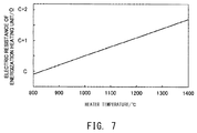
- FIG. 7 is a graph showing, as a comparative example, the relationship between the electric resistance of the energization heating unit 2 and the temperature of the heater 10.
- the vertical axis indicates the electric resistance ( ⁇ ) (hereinafter also referred to as "heating unit resistance R 2 ") of the energization heating unit 2, and the horizontal axis indicates the temperature (°C) of the heater 10.
- ⁇ electric resistance
- R 2 heating unit resistance
- the heating unit resistance R 2 in the case where abnormality occurs in the energization heating unit 2 increases only slightly as compared to the heating unit resistance R 2 in the normal state. Therefore, as shown in FIG. 7 , the rate of change in the heating unit resistance R 2 with respect to change in the temperature of the heater 10 is very small. Accordingly, the configuration of detecting abnormality of the energization heating unit 2 on the basis of the heating unit resistance R 2 has poor detection accuracy, and cannot detect slight abnormality such as a minute crack or the like generated in the energization heating unit 2.
- the heating device 100 since the heating device 100 according to the present embodiment estimates the state of the heater 10 on the basis of the base resistance R 11 that exponentially and greatly changes with respect to change in the temperature of the heater 10, the accuracy of estimating the state of the heater 10 can be improved. Further, in addition to abnormality of the energization heating unit 2, wear of the base 11 can also be estimated.
- the state of the heater 10 is estimated on the basis of the base resistance R 11 detected when the predetermined voltage is applied to the energization heating unit 2, the present invention is not limited thereto.
- the base resistance R 11 may be detected under any other energization condition as long as the energization condition is the same as that for detection of the base resistance R 11 previously set as a reference range.
- the energization heating unit 2 may be caused to generate heat at predetermined power, or may be caused to generate heat to provide a predetermined current, or may be caused to generated heat so that the electric resistance of the energization heating unit 2 has a predetermined value. Also this configuration achieves the same effect as the heating device 100 according to the embodiment.
- the state estimating unit 70 estimates abnormality of the energization heating unit 2 and wear of the base 11 to be distinguished from each other, the state estimating unit 70 may estimate the state of the heater 10 without distinguishing abnormality of the energization heating unit 2 and wear of the base 11 from each other.
- FIG. 8 is a flowchart showing the procedure of a heater state estimating process according to Modification 2.
- the heater state estimating process according to Modification 2 is different from the heater state estimating process according to the embodiment shown in FIG. 6 in that step S115a is executed instead of step S115 and steps S120 to S130 are omitted. Since other steps and the configuration of the heating device 100 in the heater state estimating process according to Modification 2 are identical to those of the above embodiment, the same components are designated by the same reference numerals, and detailed description thereof is omitted.
- the state estimating unit 70 determines whether or not the base resistance R 11 is within a predetermined range (step S115a). When it is determined that the base resistance R 11 is not within the predetermined range (step S115a: NO), the state estimating unit 70 may estimate that the heater 10 has abnormality (step S135). When it is determined that the base resistance R 11 is within the predetermined range (step S115a: YES), the state estimating unit 70 may estimate that the heater 10 has no abnormality (step S140). This configuration also achieves the same effect as the heating device 100 according to the embodiment.
- the heater state estimating process is executed when the diesel engine 600 enters the idle state
- the heater state estimating process may be executed at any other timing as long as the base resistance R 11 is detected under the same detection condition as that for the base resistance R 11 previously set as the reference range.
- the heater state estimating process may be executed at the time of idle stop, or fuel cut, or engine stop.
- the heater state estimating process may be executed after a predetermined period has passed from a certain time.
- the heater state estimating process may be executed after a predetermined period has passed from start of energization of the glow plug 1.
- the heater state estimating process may be executed after determination as to whether or not the parameters such as the temperature of the engine cooling water and the rotation speed of the engine are within a predetermined range. Also this configuration achieves the same effect as the heating device 100 according to the above embodiment.
- the state estimating unit 70 estimates the state of the heater 10 by using the preset reference range of the base resistance R 11
- the ECU 52 may store an initial value of the base resistance R 11 , and a difference between the initial value of the base resistance R 11 and the detected base resistance R 11 may be calculated to perform estimation based on the difference. For example, assuming that the initial value of the base resistance R 11 in the heater 10 in the normal state is D ( ⁇ ), when the absolute value of a difference between the initial value of the base resistance R 11 and the detected base resistance R 11 is outside the range from D ⁇ 0.5 ( ⁇ ) to D ⁇ 2.5 ( ⁇ ), it may be estimated that the heater 10 has abnormality. In this configuration, since the estimation is performed on the basis of the relative value, influence of variation in the base resistance R 11 due to individual differences of the glow plug 1 can be reduced, whereby the accuracy of estimating the state of the heater 10 can be improved.
- the state estimating unit 70 estimates the state of the heater 10 by using one preset reference range of the base resistance R 11
- the state estimating unit 70 may estimate the state of the heater 10 by using two or more reference ranges. For example, assuming that the reference resistance value of the base resistance R 11 in the heater 10 in the normal state is B ( ⁇ ), a first reference range may be set to B ⁇ 0.5 ( ⁇ ) to B ⁇ 2.5 ( ⁇ ) and a second reference range may be set to B ⁇ 0.75 ( ⁇ ) to B ⁇ 2 ( ⁇ ) or the like, whereby the state of the heater 10 may be estimated in two stages. In this configuration, when the detected base resistance R 11 is within the first reference range but is outside the second reference range, the heater 10 can be set to a desired temperature by changing the applied voltage.
- the configuration of the heating device 100 according to the above embodiment is merely an example, and can be modified in various ways.
- the base 11 may be made of, instead of the silicon nitride-based ceramic, any other insulating ceramics such as titanium diboride, alumina, or sialon.
- the electrode 3 may be made of a metal material instead of the electrically conductive ceramic. Also this configuration achieves the same effect as the heating device 100 according to the above embodiment.
- the present invention is not limited thereto.
- a glow control unit that exclusively control the glow plug 1 may be arranged separately from the ECU 52, and the glow control unit may execute the heater state estimating process.
- the glow control unit may receive the temperature of the engine cooling water, the rotation speed of the engine, and the like from the ECU 52. This configuration also achieves the same effect as the heating device 100 according to the above embodiment.
- the circuit configuration for detecting the base resistance R 11 may be modified. For example, a voltage may be applied between the pair of external lead wires 233 and 333 to measure a current value. In this configuration, it is easy to grasp the voltage applied between the energization heating unit 2 and the electrode 3, whereby the accuracy of detecting the base resistance R 11 can be improved.
- the present invention is applied to the heating device 100 including the glow plug 1
- the present invention may be applied to any other ceramic heater instead of the glow plug 1.
- the present invention may be applied to heaters, heat sources for soldering iron, warm-water toilet seats, heat sources for semiconductor manufacturing devices, heat sources for measurement equipment, parts of chemical equipment, and the like.
- the present invention is not limited to the above embodiments and modifications/variations and can be embodied in various forms without departing from the scope of the present invention.
Landscapes
- Engineering & Computer Science (AREA)
- Chemical & Material Sciences (AREA)
- Combustion & Propulsion (AREA)
- Mechanical Engineering (AREA)
- General Engineering & Computer Science (AREA)
- Control Of Resistance Heating (AREA)
- Resistance Heating (AREA)
Applications Claiming Priority (1)
| Application Number | Priority Date | Filing Date | Title |
|---|---|---|---|
| JP2015100775A JP6590521B2 (ja) | 2015-05-18 | 2015-05-18 | 加熱装置、ヒータ状態推定装置およびヒータの状態の推定方法 |
Publications (2)
| Publication Number | Publication Date |
|---|---|
| EP3096000A2 true EP3096000A2 (de) | 2016-11-23 |
| EP3096000A3 EP3096000A3 (de) | 2016-12-21 |
Family
ID=55970763
Family Applications (1)
| Application Number | Title | Priority Date | Filing Date |
|---|---|---|---|
| EP16164940.5A Withdrawn EP3096000A3 (de) | 2015-05-18 | 2016-04-12 | Heizvorrichtung, heizzustandsschätzvorrichtung und heizzustandsschätzverfahren |
Country Status (2)
| Country | Link |
|---|---|
| EP (1) | EP3096000A3 (de) |
| JP (1) | JP6590521B2 (de) |
Families Citing this family (2)
| Publication number | Priority date | Publication date | Assignee | Title |
|---|---|---|---|---|
| JP6667327B2 (ja) * | 2016-03-17 | 2020-03-18 | 日本特殊陶業株式会社 | 加熱装置及び温度推定装置 |
| JP2021012352A (ja) * | 2019-07-09 | 2021-02-04 | パナソニックi−PROセンシングソリューションズ株式会社 | 監視カメラおよびカバー |
Citations (1)
| Publication number | Priority date | Publication date | Assignee | Title |
|---|---|---|---|---|
| JP4780056B2 (ja) | 2007-08-01 | 2011-09-28 | 株式会社デンソー | グロープラグ劣化判定装置 |
Family Cites Families (6)
| Publication number | Priority date | Publication date | Assignee | Title |
|---|---|---|---|---|
| DE3742102A1 (de) * | 1987-12-11 | 1989-06-22 | Beru Werk Ruprecht Gmbh Co A | Verfahren zum regeln eines heizelementes und heizelement zur durchfuehrung dieses verfahrens |
| JPH0227695U (de) * | 1988-08-09 | 1990-02-22 | ||
| JP3605965B2 (ja) * | 1996-09-12 | 2004-12-22 | 株式会社デンソー | グロープラグ |
| JP2001336468A (ja) * | 2000-03-22 | 2001-12-07 | Ngk Spark Plug Co Ltd | グロープラグ制御装置、グロープラグ、及びエンジンの燃焼室内のイオン検出方法 |
| WO2003092330A1 (fr) * | 2002-04-26 | 2003-11-06 | Ngk Spark Plug Co., Ltd. | Element de chauffage en ceramique et bougie de prechauffage comprenant ledit element |
| DE102013200277A1 (de) * | 2013-01-10 | 2014-01-30 | E.G.O. Elektro-Gerätebau GmbH | Heizeinrichtung und Verfahren zur Temperaturmessung an der Heizeinrichtung |
-
2015
- 2015-05-18 JP JP2015100775A patent/JP6590521B2/ja not_active Expired - Fee Related
-
2016
- 2016-04-12 EP EP16164940.5A patent/EP3096000A3/de not_active Withdrawn
Patent Citations (1)
| Publication number | Priority date | Publication date | Assignee | Title |
|---|---|---|---|---|
| JP4780056B2 (ja) | 2007-08-01 | 2011-09-28 | 株式会社デンソー | グロープラグ劣化判定装置 |
Also Published As
| Publication number | Publication date |
|---|---|
| JP6590521B2 (ja) | 2019-10-16 |
| JP2016219173A (ja) | 2016-12-22 |
| EP3096000A3 (de) | 2016-12-21 |
Similar Documents
| Publication | Publication Date | Title |
|---|---|---|
| JP5240679B2 (ja) | 検出装置 | |
| JP3605965B2 (ja) | グロープラグ | |
| US9074575B2 (en) | Energization control apparatus for glow plug | |
| JP2001336468A (ja) | グロープラグ制御装置、グロープラグ、及びエンジンの燃焼室内のイオン検出方法 | |
| EP3096000A2 (de) | Heizvorrichtung, heizzustandsschätzvorrichtung und heizzustandsschätzverfahren | |
| EP2827061B1 (de) | Keramische glühkerze | |
| KR100697543B1 (ko) | 세라믹 글로우 플러그 | |
| HUP0202789A2 (en) | Ceramic sheathed element glow plug | |
| JP4816385B2 (ja) | グロープラグ | |
| EP3046395B1 (de) | Heizvorrichtung, temperaturschätzungsvorrichtung und heizungsregelungsvorrichtung | |
| JP3674231B2 (ja) | グロープラグ及びその製造方法 | |
| JPH1089687A (ja) | グロープラグ | |
| JP3785699B2 (ja) | グロープラグ | |
| CN102933903B (zh) | 加热器及具备该加热器的火花塞 | |
| JP3823393B2 (ja) | グロープラグ | |
| EP3045714B1 (de) | Ionenstrommessvorrichtung | |
| JP3785698B2 (ja) | グロープラグ | |
| JP3605990B2 (ja) | イオン電流検出装置及びそれに用いられるグロープラグ | |
| JP6736254B2 (ja) | グロープラグ | |
| JP2018013083A (ja) | 排気加熱用の電熱ヒータシステム | |
| JP6667327B2 (ja) | 加熱装置及び温度推定装置 | |
| JPH1144282A (ja) | イオン電流検出装置 | |
| JPH10110950A (ja) | グロープラグ及びその製造方法 | |
| JP2001295744A (ja) | イオン電流検出装置 | |
| JPH11248156A (ja) | グロー装置 |
Legal Events
| Date | Code | Title | Description |
|---|---|---|---|
| PUAI | Public reference made under article 153(3) epc to a published international application that has entered the european phase |
Free format text: ORIGINAL CODE: 0009012 |
|
| PUAL | Search report despatched |
Free format text: ORIGINAL CODE: 0009013 |
|
| AK | Designated contracting states |
Kind code of ref document: A2 Designated state(s): AL AT BE BG CH CY CZ DE DK EE ES FI FR GB GR HR HU IE IS IT LI LT LU LV MC MK MT NL NO PL PT RO RS SE SI SK SM TR |
|
| AX | Request for extension of the european patent |
Extension state: BA ME |
|
| AK | Designated contracting states |
Kind code of ref document: A3 Designated state(s): AL AT BE BG CH CY CZ DE DK EE ES FI FR GB GR HR HU IE IS IT LI LT LU LV MC MK MT NL NO PL PT RO RS SE SI SK SM TR |
|
| AX | Request for extension of the european patent |
Extension state: BA ME |
|
| RIC1 | Information provided on ipc code assigned before grant |
Ipc: F23Q 7/00 20060101ALI20161111BHEP Ipc: F02P 19/02 20060101AFI20161111BHEP |
|
| STAA | Information on the status of an ep patent application or granted ep patent |
Free format text: STATUS: REQUEST FOR EXAMINATION WAS MADE |
|
| 17P | Request for examination filed |
Effective date: 20170609 |
|
| RBV | Designated contracting states (corrected) |
Designated state(s): AL AT BE BG CH CY CZ DE DK EE ES FI FR GB GR HR HU IE IS IT LI LT LU LV MC MK MT NL NO PL PT RO RS SE SI SK SM TR |
|
| STAA | Information on the status of an ep patent application or granted ep patent |
Free format text: STATUS: EXAMINATION IS IN PROGRESS |
|
| 17Q | First examination report despatched |
Effective date: 20190916 |
|
| RAP3 | Party data changed (applicant data changed or rights of an application transferred) |
Owner name: NITERRA CO., LTD. |
|
| STAA | Information on the status of an ep patent application or granted ep patent |
Free format text: STATUS: THE APPLICATION IS DEEMED TO BE WITHDRAWN |
|
| 18D | Application deemed to be withdrawn |
Effective date: 20240312 |