EP3045722B1 - Fester wobbler für hydraulikbaugruppe - Google Patents
Fester wobbler für hydraulikbaugruppe Download PDFInfo
- Publication number
- EP3045722B1 EP3045722B1 EP16151327.0A EP16151327A EP3045722B1 EP 3045722 B1 EP3045722 B1 EP 3045722B1 EP 16151327 A EP16151327 A EP 16151327A EP 3045722 B1 EP3045722 B1 EP 3045722B1
- Authority
- EP
- European Patent Office
- Prior art keywords
- approximately
- inches
- wobbler
- fixed
- fixed wobbler
- Prior art date
- Legal status (The legal status is an assumption and is not a legal conclusion. Google has not performed a legal analysis and makes no representation as to the accuracy of the status listed.)
- Active
Links
Images



Classifications
-
- F—MECHANICAL ENGINEERING; LIGHTING; HEATING; WEAPONS; BLASTING
- F15—FLUID-PRESSURE ACTUATORS; HYDRAULICS OR PNEUMATICS IN GENERAL
- F15B—SYSTEMS ACTING BY MEANS OF FLUIDS IN GENERAL; FLUID-PRESSURE ACTUATORS, e.g. SERVOMOTORS; DETAILS OF FLUID-PRESSURE SYSTEMS, NOT OTHERWISE PROVIDED FOR
- F15B15/00—Fluid-actuated devices for displacing a member from one position to another; Gearing associated therewith
- F15B15/08—Characterised by the construction of the motor unit
- F15B15/14—Characterised by the construction of the motor unit of the straight-cylinder type
- F15B15/1404—Characterised by the construction of the motor unit of the straight-cylinder type in clusters, e.g. multiple cylinders in one block
-
- F—MECHANICAL ENGINEERING; LIGHTING; HEATING; WEAPONS; BLASTING
- F04—POSITIVE - DISPLACEMENT MACHINES FOR LIQUIDS; PUMPS FOR LIQUIDS OR ELASTIC FLUIDS
- F04B—POSITIVE-DISPLACEMENT MACHINES FOR LIQUIDS; PUMPS
- F04B1/00—Multi-cylinder machines or pumps characterised by number or arrangement of cylinders
- F04B1/12—Multi-cylinder machines or pumps characterised by number or arrangement of cylinders having cylinder axes coaxial with, or parallel or inclined to, main shaft axis
- F04B1/20—Multi-cylinder machines or pumps characterised by number or arrangement of cylinders having cylinder axes coaxial with, or parallel or inclined to, main shaft axis having rotary cylinder block
- F04B1/2014—Details or component parts
- F04B1/2078—Swash plates
Definitions
- Exemplary embodiments of this invention generally relate to an integrated drive generator, and more particularly, to a fixed wobbler of a hydraulic unit of an integrated drive generator.
- a typical electrical system utilizes an integrated drive generator (IDG) coupled to each engine to provide a fixed frequency power to the distribution system and loads.
- IDG integrated drive generator
- One type of IDG includes a generator, a hydraulic unit, and a differential assembly arranged in a common housing.
- the differential assembly is operably coupled to a gas turbine engine via an input shaft. The rotational speed of the input shaft varies during the operation of the gas turbine engine.
- the hydraulic unit cooperates with the differential assembly to provide a constant speed to the generator throughout engine operation.
- variable and fixed wobblers Due to packaging constraints, components of the hydraulic unit, such as variable and fixed wobblers must be redesigned.
- a fixed wobbler having no radius at an inner shoulder of its cut out is disclosed in DE 2253419 A1 .
- Other fixed wobblers are disclosed in DE 584665 C1 and DE 10 2008 060491 A1 .
- the angle is between approximately 12.75° and approximately 16.75°, for example approximately 14.75°.
- the body may further comprise a locking feature formed in the body outer diameter, the locking feature defined by an inner rear wall and a pair of side walls; wherein the locking feature has a length of approximately 0.503 ⁇ 0.010 inches (1.2777 ⁇ 0.0254 cm).
- a distance between the side walls may be approximately 0.250 +0.005-0.000 inches (0.635 +0.0127 -0.000 cm).
- a distance from the inner rear wall to a centerpoint of the outer diameter may be approximately 0.982 +0.000 -0.010 inches (2.4943 +0.000 -0.0254).
- the second surface may comprise a friction-reducing coating, which may be between approximately 3 microns and approximately 5 microns.
- the friction-reducing coating may be an Amorphous Diamond-like Carbon Coating.
- the inner wall may include a corner break that is less than or equal to approximately 0.005 inches (0.0127 cm).
- the body first end may include a first corner break disposed adjacent to a second corner break, the first corner break oriented relative to the first surface at a second angle, wherein the second angle is approximately 40° +0.00° -0.25°.
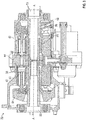
- the system 10 includes a gas turbine engine 12 that provides rotational drive to an integrated drive generator (IDG) 16 through an accessory drive gearbox 14 mounted on the gas turbine engine 12.
- IDG integrated drive generator
- the accessory drive gearbox is coupled to a spool of the engine 12, and the speed of the spool varies throughout the entire engine operation.
- FIG. 2 An example of an IDG 16 including a housing 18 is shown in FIG. 2 .
- the IDG 16 includes an input shaft configured to receive rotational drive from the accessory drive gearbox 14. The rotational speed of the input shaft varies depending upon the operation of the engine.
- a hydraulic unit 32 cooperates with the differential assembly 28 to convert the variable rotational speed from the input shaft to a fixed rotational output speed to the generator 24.
- the hydraulic unit 32 includes a variable displacement hydraulic pump 34 and a fixed displacement hydraulic motor 36.
- the pump 34 and motor 36 have respective cylinder blocks 38 and 40 which are arranged for rotation about a common axis A within a housing 42 on opposite sides of a stationary port plate 44 of the hydraulic unit 32.
- the port plate 44 is formed with apertures 46 through which hydraulic fluid communication between the pump 34 and the motor 36 is established during normal operation of the hydraulic unit 32.
- a biasing mechanism 48 resiliently biases the cylinder blocks 38, 40 in the direction of the port plate 44.
- the operation of the hydraulic unit 32 in an IDG 16 of an aircraft involves transmission of torque from an engine of the airplane to an input, which rotates the input shaft 50 of the hydraulic unit 32 about axis A.
- the cylinder block 38 of the pump 34 is connected to the input shaft 50 for rotation therewith.
- Pistons 52 within the cylinder block 38 of the pump 34 are displaced during this rotation an amount which is a function of the setting of a variable wobbler 54 of the pump 34.
- Variable wobbler 54 sets the stroke of each piston 52 depending on its angular position around axis A and on the setting of the wobbler itself.
- Hydraulic fluid under pressure from the pump 34 is delivered to the hydraulic motor 36 through the port plate 44 for rotating the cylinder block 40 and an output shaft 56 to which it is fixedly connected.
- a fixed wobbler 58 of the motor 36 is fixed so that the operating speed of the motor 36 is a function of the displacement of the pump 34.
- Fixed wobbler 58 sets the stroke of each piston 52 depending on its angular position around axis A.
- the rotary output from output shaft 56 is added to or subtracted from the rotary motion from the engine through the conventional differential gearing of an IDG 16 for operating an electrical generator at a substantially constant rotational speed.
- the position of the variable wobbler 54 is adjusted in response to these detected speed variations for providing the necessary reduction or increase in this speed for obtaining the desired constant output speed to the generator.
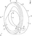
- Fixed wobbler 58 includes a body 62 having a first end 64 and a second, opposite end 66.
- First end 64 defines a first surface 68
- second end 66 defines a second surface 70 configured to contact pistons 52.
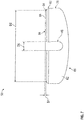
- second surface 70 is oriented with respect to first surface 68 at an angle ⁇ .
- angle ⁇ is between approximately 12.75° and approximately 16.75°.
- angle ⁇ is between 12.75° and 16.75°.
- angle ⁇ is approximately 14.75°.
- angle ⁇ is 14.75°.
- Second surface 70 is configured to contact and reciprocate/translate pistons 52 along an axis parallel to axis A ( FIG. 3 ).
- First end 64 includes a cutout 72 formed in first surface 68 and defining a cutout surface 74, for example, to reduce size and weight of fixed wobbler 58.
- Cutout surface 74 defines an inner shoulder 75 ( FIG. 6 ).
- Inner shoulder 75 has a radius of approximately 0.156 ⁇ 0.015 inches (0.3962 ⁇ 0.1381 cm).
- First surface 68 may include a coating to reduce friction and wear between surface 70 and pistons 52.
- the coating is titanium nitride disposed by physical vapor deposition.
- other friction-reducing coating materials e.g., Amorphous Diamond-like Carbon Coating
- additional portions and surfaces of fixed wobbler 58 may include the coating described herein (e.g., cutout surface 74).
- the coating has a thickness of approximately 1-4 microns.
- the coating has a thickness of 1-4 microns.
- the coating has a thickness of approximately 3-5 microns.
- the coating has a thickness of 3-5 microns.
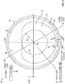
- Body 62 defines an outer diameter 76 and includes an inner wall 78 defining an inner diameter 80.
- Outer diameter 76 is approximately 2.1655 +0.0000 -0.0007 inches (5.5004 +0.000 -0.0018 cm).
- Outer diameter 76 may include a corner break 77 ( FIG. 6 ).
- corner break 77 is less than or equal to approximately 0.005 inches (0.0127 cm). In another embodiment, corner break 77 is less than or equal to 0.005 inches.
- Inner diameter 80 is approximately 1.043 ⁇ 0.003 inches (2.6492 ⁇ 0.0076 cm). As illustrated in FIG. 6 , inner wall 78 has a depth D. In one embodiment, depth D is approximately 0.250 ⁇ 0.015 inches (0.635 ⁇ 0.0381 cm). In another embodiment, depth D is 0.250 ⁇ 0.015 inches. Inner wall may include a corner break 81 ( FIG. 6 ). In one embodiment, corner break 81 is less than or equal to approximately 0.005 inches (0.0127 cm). In another embodiment, corner break 81 is less than or equal to 0.005 inches.
- first end 64 includes a first corner break 82 and a second corner break 84.
- first corner break 82 is approximately 0.035 ⁇ 0.010 inches (0.0889 ⁇ 0.0254 cm). In another embodiment, first corner break 82 is 0.035 ⁇ 0.010 inches.
- a distance D1 from a point (e.g., a midpoint) of second corner break 84 to first surface 68 is approximately 0.032 ⁇ 0.005 inches (0.0813 ⁇ 0.0127 cm). In another embodiment, distance D1 is 0.032 ⁇ 0.005 inches.
- a distance D2 between diametrically disposed midpoints of second corner break 84 is approximately 2.064 inches (5.2426 cm).
- distance D2 is 2.064 inches.
- second corner break 84 is oriented at an angle of approximately 40° +0.00° -0.25° relative to first surface 68. In another embodiment, second corner break 84 is oriented at an angle of 40° +0.00° -0.25°.
- Body 62 includes a locking feature or key 86 formed in outer diameter 76.
- Key 86 is configured to receive a portion of housing 42 or other component (e.g., a stepped pin) to facilitate preventing rotation of fixed wobbler 58 within housing 42.
- Key 86 includes inner rounded corners 88, an inner rear wall 90, and side walls 92 ( FIG. 5 ). In one embodiment, rounded corners 88 have a radius of approximately 0.010 ⁇ 0.005 inches (0.0254 ⁇ 0.0127 cm). In another embodiment, rounded corners 88 have a radius of 0.010 ⁇ 0.005 inches.
- Key 86 includes a length L1 ( FIG. 6 ) extending along outer diameter 76.
- L1 is approximately 0.503 ⁇ 0.010 inches (0.1.278 ⁇ 0.0254 cm). In another embodiment, L1 is 0.503 ⁇ 0.010 inches.
- Body 62 includes a distance D3 between inner rear wall 90 and a centerpoint 94 of outer diameter 76 ( FIG. 6 ). In one embodiment, distance D3 is approximately 0.982 +0.000 -0.010 inches (2.4943 +0.000 - 0.0254 cm). In another embodiment, distance D3 is 0.982 +0.000-0.010 inches.
- Body 62 includes a distance D4 between centerpoint 94 and first surface 68 ( FIG. 6 ). In one embodiment, distance D4 is approximately 0.392 inches (0.9957 cm). In another embodiment, distance D4 is 0.392 inches.
- distance D5 is approximately 0.250 +0.005-0.000 inches (0.635 +0.0127 -0.000 cm). In another embodiment, distance D5 is 0.250 +0.005 -0.000 inches.
Landscapes
- Engineering & Computer Science (AREA)
- Mechanical Engineering (AREA)
- General Engineering & Computer Science (AREA)
- Physics & Mathematics (AREA)
- Fluid Mechanics (AREA)
- Hydraulic Motors (AREA)
- Control Of Turbines (AREA)
- Prostheses (AREA)
Claims (12)
- Fester Wobbler (58) für eine Hydraulikbaugruppe, wobei der feste Wobbler (58) Folgendes umfasst:einen Körper (62), der ein erstes Ende (64) und ein gegenüberliegendes zweites Ende (66) aufweist, wobei das erste Ende (64) eine erste Fläche (68) definiert und das zweite Ende (66) eine zweite Fläche (70) definiert, die in einem Winkel (α) relativ zu der ersten Fläche (68) ausgerichtet ist, wobei der Körper (62) einen Außendurchmesser (76) und eine Innenwand (78), die einen Innendurchmesser (80) definiert, aufweist; wobei der Außendurchmesser (76) ungefähr 2,1655+0,0000-0,0007 Inches (5,5004+0,000-0,0018 cm) beträgt und der Innendurchmesser (80) ungefähr 1,043±0,003 Inches (2,6492±0,0076 cm) beträgt, und wobeider Körper (62) ferner eine Aussparung (72) umfasst, die in der ersten Fläche (68) um wenigstens einen Abschnitt der Innenwand (78) ausgebildet ist, wobei die Aussparung (72) eine Innenschulter (75) definiert, die einen Radius von ungefähr 0,156±0,015 Inches (0,3962±0,1381 cm) aufweist.
- Fester Wobbler nach Anspruch 1, wobei der Winkel (α) zwischen ungefähr 12,75° und ungefähr 16,75° beträgt.
- Fester Wobbler nach Anspruch 2, wobei der Winkel ungefähr 14,75°beträgt.
- Fester Wobbler nach einem der vorhergehenden Ansprüche, wobei der Körper (62) ferner ein Verriegelungsmerkmal (86) umfasst, das in dem Außendurchmesser (76) des Körpers ausgebildet ist, wobei das Verriegelungsmerkmal (86) von einer Innenrückwand (90) und einem Paar von Seitenwänden (92) definiert wird.
- Fester Wobbler nach Anspruch 4, wobei das Verriegelungsmerkmal (86) eine Länge von ungefähr 0,503±0,010 Inches (1,2777±0,0254 cm) aufweist.
- Fester Wobbler nach Anspruch 4 oder 5, wobei ein Abstand zwischen den Seitenwänden (92) ungefähr 0,250+0,005-0,000 Inches (0,635+0,0127-0,000 cm) beträgt.
- Fester Wobbler nach Anspruch 4, 5 oder 6, wobei ein Abstand (D3) von der Innenrückwand (90) zu einem Mittelpunkt (94) des Außendurchmessers (76) ungefähr 0,982+0,000-0,010 Inches (2,4943+0,000-0,0254 cm) beträgt.
- Fester Wobbler nach einem der vorhergehenden Ansprüche, wobei die zweite Fläche (70) eine reibungsreduzierende Beschichtung umfasst.
- Fester Wobbler nach Anspruch 8, wobei die reibungsreduzierende Beschichtung zwischen ungefähr 3 Mikrometer und 5 Mikrometer beträgt.
- Fester Wobbler nach Anspruch 8 oder 9, wobei die reibungsreduzierende Beschichtung eine amorphe diamantartige Kohlenstoffbeschichtung ist.
- Fester Wobbler nach einem der vorhergehenden Ansprüche, wobei die Innenwand (78) eine Eckverbindung (81) einschließt, die geringer als oder gleich ungefähr 0,005 Inches (0,0127 cm) ist.
- Fester Wobbler nach einem der vorhergehenden Ansprüche, wobei das erste Ende (64) des Körpers eine erste Eckverbindung (82) einschließt, die benachbart einer zweiten Eckverbindung (84) angeordnet ist, wobei die erste Eckverbindung (82) relativ zu der ersten Fläche (68) in einem zweiten Winkel ausgerichtet ist, wobei der zweite Winkel ungefähr 40°+0,00°-0,25° beträgt.
Applications Claiming Priority (1)
| Application Number | Priority Date | Filing Date | Title |
|---|---|---|---|
| US14/596,439 US10273990B2 (en) | 2015-01-14 | 2015-01-14 | Fixed wobbler for hydraulic unit |
Publications (2)
| Publication Number | Publication Date |
|---|---|
| EP3045722A1 EP3045722A1 (de) | 2016-07-20 |
| EP3045722B1 true EP3045722B1 (de) | 2018-08-01 |
Family
ID=55129779
Family Applications (1)
| Application Number | Title | Priority Date | Filing Date |
|---|---|---|---|
| EP16151327.0A Active EP3045722B1 (de) | 2015-01-14 | 2016-01-14 | Fester wobbler für hydraulikbaugruppe |
Country Status (2)
| Country | Link |
|---|---|
| US (1) | US10273990B2 (de) |
| EP (1) | EP3045722B1 (de) |
Family Cites Families (8)
| Publication number | Priority date | Publication date | Assignee | Title |
|---|---|---|---|---|
| DE584665C (de) | 1933-09-22 | Heinz Krienelke | Kolbenpumpe | |
| DE2253419A1 (de) | 1972-10-31 | 1974-05-02 | Linde Ag | Axialkolbenmaschine |
| KR970002532B1 (ko) * | 1993-12-30 | 1997-03-05 | 재단법인 한국기계연구원 | 사판식 유압모터의 변속기구 |
| JP2002005013A (ja) * | 2000-06-27 | 2002-01-09 | Toyota Industries Corp | 斜板式圧縮機 |
| KR100714088B1 (ko) * | 2001-02-16 | 2007-05-02 | 한라공조주식회사 | 사판의 가공방법 및 이를 이용한 사판식 가변용량 압축기 |
| US20050025629A1 (en) * | 2003-07-30 | 2005-02-03 | Ford Michael Brent | Method for protecting pump components |
| DE102008060491A1 (de) | 2008-12-04 | 2010-06-10 | Robert Bosch Gmbh | Axialkolbenmaschine und Steuerplatte mit Verschleißschutzschicht |
| US20110314963A1 (en) | 2010-06-28 | 2011-12-29 | Hamilton Sundstrand Corporation | Controllable constant speed gearbox |
-
2015
- 2015-01-14 US US14/596,439 patent/US10273990B2/en active Active
-
2016
- 2016-01-14 EP EP16151327.0A patent/EP3045722B1/de active Active
Also Published As
| Publication number | Publication date |
|---|---|
| US10273990B2 (en) | 2019-04-30 |
| US20160201698A1 (en) | 2016-07-14 |
| EP3045722A1 (de) | 2016-07-20 |
Similar Documents
| Publication | Publication Date | Title |
|---|---|---|
| EP3045721A1 (de) | Variables taumelelement für hydraulikeinheit | |
| EP3023616B1 (de) | Variable welle für hydraulikeinheit | |
| EP3023651B1 (de) | Festwelle für hydraulikeinheit | |
| EP3045722B1 (de) | Fester wobbler für hydraulikbaugruppe | |
| US20160273531A1 (en) | Cylinder block assembly for hydraulic unit | |
| US9435378B1 (en) | Roller bearing outer race for hydraulic unit | |
| EP3048302B1 (de) | Gleitschuhhalter für hydraulikeinheit | |
| US9714702B2 (en) | Variable coaxial shaft for hydraulic unit | |
| US11002259B2 (en) | Variable wobbler for a hydraulic unit | |
| EP3034900B1 (de) | Feste koaxiale welle für ein hydraulikaggregat | |
| EP3061965B1 (de) | Wälzlageraussenring einer hydraulikeinheit | |
| EP3489532B1 (de) | Verschleissring für einen integrierten antriebsgenerator | |
| EP3045720B1 (de) | Gleitschuhhalterkugel für hydraulikeinheit | |
| EP3211228B1 (de) | Hydraulikmaschine und windturbinenstromerzeugungsvorrichtung | |
| US10707792B2 (en) | Variable wobbler plate for integrated drive generator | |
| US20190219139A1 (en) | Fixed block shaft for integrated drive generator | |
| US10670126B2 (en) | Variable block shaft for integrated drive generator | |
| EP3073111A1 (de) | Kolben- und gleitschuhanordnung für eine hydraulikbaugruppe | |
| EP3473896B1 (de) | Dichtungsplatte zwischen zwei gehäuseabschnitten in einem integrierten antriebsgenerator |
Legal Events
| Date | Code | Title | Description |
|---|---|---|---|
| PUAI | Public reference made under article 153(3) epc to a published international application that has entered the european phase |
Free format text: ORIGINAL CODE: 0009012 |
|
| AK | Designated contracting states |
Kind code of ref document: A1 Designated state(s): AL AT BE BG CH CY CZ DE DK EE ES FI FR GB GR HR HU IE IS IT LI LT LU LV MC MK MT NL NO PL PT RO RS SE SI SK SM TR |
|
| AX | Request for extension of the european patent |
Extension state: BA ME |
|
| STAA | Information on the status of an ep patent application or granted ep patent |
Free format text: STATUS: REQUEST FOR EXAMINATION WAS MADE |
|
| 17P | Request for examination filed |
Effective date: 20170118 |
|
| RBV | Designated contracting states (corrected) |
Designated state(s): AL AT BE BG CH CY CZ DE DK EE ES FI FR GB GR HR HU IE IS IT LI LT LU LV MC MK MT NL NO PL PT RO RS SE SI SK SM TR |
|
| GRAP | Despatch of communication of intention to grant a patent |
Free format text: ORIGINAL CODE: EPIDOSNIGR1 |
|
| STAA | Information on the status of an ep patent application or granted ep patent |
Free format text: STATUS: GRANT OF PATENT IS INTENDED |
|
| RIC1 | Information provided on ipc code assigned before grant |
Ipc: F04B 1/20 20060101AFI20180117BHEP |
|
| INTG | Intention to grant announced |
Effective date: 20180213 |
|
| GRAS | Grant fee paid |
Free format text: ORIGINAL CODE: EPIDOSNIGR3 |
|
| GRAA | (expected) grant |
Free format text: ORIGINAL CODE: 0009210 |
|
| STAA | Information on the status of an ep patent application or granted ep patent |
Free format text: STATUS: THE PATENT HAS BEEN GRANTED |
|
| AK | Designated contracting states |
Kind code of ref document: B1 Designated state(s): AL AT BE BG CH CY CZ DE DK EE ES FI FR GB GR HR HU IE IS IT LI LT LU LV MC MK MT NL NO PL PT RO RS SE SI SK SM TR |
|
| REG | Reference to a national code |
Ref country code: GB Ref legal event code: FG4D |
|
| REG | Reference to a national code |
Ref country code: CH Ref legal event code: EP Ref country code: AT Ref legal event code: REF Ref document number: 1024619 Country of ref document: AT Kind code of ref document: T Effective date: 20180815 |
|
| REG | Reference to a national code |
Ref country code: IE Ref legal event code: FG4D |
|
| REG | Reference to a national code |
Ref country code: DE Ref legal event code: R096 Ref document number: 602016004325 Country of ref document: DE |
|
| REG | Reference to a national code |
Ref country code: NL Ref legal event code: MP Effective date: 20180801 |
|
| REG | Reference to a national code |
Ref country code: LT Ref legal event code: MG4D |
|
| REG | Reference to a national code |
Ref country code: AT Ref legal event code: MK05 Ref document number: 1024619 Country of ref document: AT Kind code of ref document: T Effective date: 20180801 |
|
| PG25 | Lapsed in a contracting state [announced via postgrant information from national office to epo] |
Ref country code: LT Free format text: LAPSE BECAUSE OF FAILURE TO SUBMIT A TRANSLATION OF THE DESCRIPTION OR TO PAY THE FEE WITHIN THE PRESCRIBED TIME-LIMIT Effective date: 20180801 Ref country code: RS Free format text: LAPSE BECAUSE OF FAILURE TO SUBMIT A TRANSLATION OF THE DESCRIPTION OR TO PAY THE FEE WITHIN THE PRESCRIBED TIME-LIMIT Effective date: 20180801 Ref country code: AT Free format text: LAPSE BECAUSE OF FAILURE TO SUBMIT A TRANSLATION OF THE DESCRIPTION OR TO PAY THE FEE WITHIN THE PRESCRIBED TIME-LIMIT Effective date: 20180801 Ref country code: IS Free format text: LAPSE BECAUSE OF FAILURE TO SUBMIT A TRANSLATION OF THE DESCRIPTION OR TO PAY THE FEE WITHIN THE PRESCRIBED TIME-LIMIT Effective date: 20181201 Ref country code: PL Free format text: LAPSE BECAUSE OF FAILURE TO SUBMIT A TRANSLATION OF THE DESCRIPTION OR TO PAY THE FEE WITHIN THE PRESCRIBED TIME-LIMIT Effective date: 20180801 Ref country code: NL Free format text: LAPSE BECAUSE OF FAILURE TO SUBMIT A TRANSLATION OF THE DESCRIPTION OR TO PAY THE FEE WITHIN THE PRESCRIBED TIME-LIMIT Effective date: 20180801 Ref country code: BG Free format text: LAPSE BECAUSE OF FAILURE TO SUBMIT A TRANSLATION OF THE DESCRIPTION OR TO PAY THE FEE WITHIN THE PRESCRIBED TIME-LIMIT Effective date: 20181101 Ref country code: NO Free format text: LAPSE BECAUSE OF FAILURE TO SUBMIT A TRANSLATION OF THE DESCRIPTION OR TO PAY THE FEE WITHIN THE PRESCRIBED TIME-LIMIT Effective date: 20181101 Ref country code: GR Free format text: LAPSE BECAUSE OF FAILURE TO SUBMIT A TRANSLATION OF THE DESCRIPTION OR TO PAY THE FEE WITHIN THE PRESCRIBED TIME-LIMIT Effective date: 20181102 Ref country code: FI Free format text: LAPSE BECAUSE OF FAILURE TO SUBMIT A TRANSLATION OF THE DESCRIPTION OR TO PAY THE FEE WITHIN THE PRESCRIBED TIME-LIMIT Effective date: 20180801 Ref country code: SE Free format text: LAPSE BECAUSE OF FAILURE TO SUBMIT A TRANSLATION OF THE DESCRIPTION OR TO PAY THE FEE WITHIN THE PRESCRIBED TIME-LIMIT Effective date: 20180801 |
|
| PG25 | Lapsed in a contracting state [announced via postgrant information from national office to epo] |
Ref country code: HR Free format text: LAPSE BECAUSE OF FAILURE TO SUBMIT A TRANSLATION OF THE DESCRIPTION OR TO PAY THE FEE WITHIN THE PRESCRIBED TIME-LIMIT Effective date: 20180801 Ref country code: AL Free format text: LAPSE BECAUSE OF FAILURE TO SUBMIT A TRANSLATION OF THE DESCRIPTION OR TO PAY THE FEE WITHIN THE PRESCRIBED TIME-LIMIT Effective date: 20180801 Ref country code: LV Free format text: LAPSE BECAUSE OF FAILURE TO SUBMIT A TRANSLATION OF THE DESCRIPTION OR TO PAY THE FEE WITHIN THE PRESCRIBED TIME-LIMIT Effective date: 20180801 |
|
| PG25 | Lapsed in a contracting state [announced via postgrant information from national office to epo] |
Ref country code: CZ Free format text: LAPSE BECAUSE OF FAILURE TO SUBMIT A TRANSLATION OF THE DESCRIPTION OR TO PAY THE FEE WITHIN THE PRESCRIBED TIME-LIMIT Effective date: 20180801 Ref country code: IT Free format text: LAPSE BECAUSE OF FAILURE TO SUBMIT A TRANSLATION OF THE DESCRIPTION OR TO PAY THE FEE WITHIN THE PRESCRIBED TIME-LIMIT Effective date: 20180801 Ref country code: RO Free format text: LAPSE BECAUSE OF FAILURE TO SUBMIT A TRANSLATION OF THE DESCRIPTION OR TO PAY THE FEE WITHIN THE PRESCRIBED TIME-LIMIT Effective date: 20180801 Ref country code: EE Free format text: LAPSE BECAUSE OF FAILURE TO SUBMIT A TRANSLATION OF THE DESCRIPTION OR TO PAY THE FEE WITHIN THE PRESCRIBED TIME-LIMIT Effective date: 20180801 Ref country code: ES Free format text: LAPSE BECAUSE OF FAILURE TO SUBMIT A TRANSLATION OF THE DESCRIPTION OR TO PAY THE FEE WITHIN THE PRESCRIBED TIME-LIMIT Effective date: 20180801 |
|
| REG | Reference to a national code |
Ref country code: DE Ref legal event code: R097 Ref document number: 602016004325 Country of ref document: DE |
|
| PG25 | Lapsed in a contracting state [announced via postgrant information from national office to epo] |
Ref country code: SM Free format text: LAPSE BECAUSE OF FAILURE TO SUBMIT A TRANSLATION OF THE DESCRIPTION OR TO PAY THE FEE WITHIN THE PRESCRIBED TIME-LIMIT Effective date: 20180801 Ref country code: DK Free format text: LAPSE BECAUSE OF FAILURE TO SUBMIT A TRANSLATION OF THE DESCRIPTION OR TO PAY THE FEE WITHIN THE PRESCRIBED TIME-LIMIT Effective date: 20180801 Ref country code: SK Free format text: LAPSE BECAUSE OF FAILURE TO SUBMIT A TRANSLATION OF THE DESCRIPTION OR TO PAY THE FEE WITHIN THE PRESCRIBED TIME-LIMIT Effective date: 20180801 |
|
| PLBE | No opposition filed within time limit |
Free format text: ORIGINAL CODE: 0009261 |
|
| STAA | Information on the status of an ep patent application or granted ep patent |
Free format text: STATUS: NO OPPOSITION FILED WITHIN TIME LIMIT |
|
| 26N | No opposition filed |
Effective date: 20190503 |
|
| REG | Reference to a national code |
Ref country code: DE Ref legal event code: R119 Ref document number: 602016004325 Country of ref document: DE |
|
| PG25 | Lapsed in a contracting state [announced via postgrant information from national office to epo] |
Ref country code: MC Free format text: LAPSE BECAUSE OF FAILURE TO SUBMIT A TRANSLATION OF THE DESCRIPTION OR TO PAY THE FEE WITHIN THE PRESCRIBED TIME-LIMIT Effective date: 20180801 Ref country code: SI Free format text: LAPSE BECAUSE OF FAILURE TO SUBMIT A TRANSLATION OF THE DESCRIPTION OR TO PAY THE FEE WITHIN THE PRESCRIBED TIME-LIMIT Effective date: 20180801 |
|
| REG | Reference to a national code |
Ref country code: CH Ref legal event code: PL |
|
| PG25 | Lapsed in a contracting state [announced via postgrant information from national office to epo] |
Ref country code: LU Free format text: LAPSE BECAUSE OF NON-PAYMENT OF DUE FEES Effective date: 20190114 |
|
| REG | Reference to a national code |
Ref country code: BE Ref legal event code: MM Effective date: 20190131 |
|
| REG | Reference to a national code |
Ref country code: IE Ref legal event code: MM4A |
|
| PG25 | Lapsed in a contracting state [announced via postgrant information from national office to epo] |
Ref country code: DE Free format text: LAPSE BECAUSE OF NON-PAYMENT OF DUE FEES Effective date: 20190801 |
|
| PG25 | Lapsed in a contracting state [announced via postgrant information from national office to epo] |
Ref country code: BE Free format text: LAPSE BECAUSE OF NON-PAYMENT OF DUE FEES Effective date: 20190131 |
|
| PG25 | Lapsed in a contracting state [announced via postgrant information from national office to epo] |
Ref country code: CH Free format text: LAPSE BECAUSE OF NON-PAYMENT OF DUE FEES Effective date: 20190131 Ref country code: LI Free format text: LAPSE BECAUSE OF NON-PAYMENT OF DUE FEES Effective date: 20190131 |
|
| PG25 | Lapsed in a contracting state [announced via postgrant information from national office to epo] |
Ref country code: IE Free format text: LAPSE BECAUSE OF NON-PAYMENT OF DUE FEES Effective date: 20190114 |
|
| PG25 | Lapsed in a contracting state [announced via postgrant information from national office to epo] |
Ref country code: TR Free format text: LAPSE BECAUSE OF FAILURE TO SUBMIT A TRANSLATION OF THE DESCRIPTION OR TO PAY THE FEE WITHIN THE PRESCRIBED TIME-LIMIT Effective date: 20180801 |
|
| PG25 | Lapsed in a contracting state [announced via postgrant information from national office to epo] |
Ref country code: PT Free format text: LAPSE BECAUSE OF FAILURE TO SUBMIT A TRANSLATION OF THE DESCRIPTION OR TO PAY THE FEE WITHIN THE PRESCRIBED TIME-LIMIT Effective date: 20181201 Ref country code: MT Free format text: LAPSE BECAUSE OF NON-PAYMENT OF DUE FEES Effective date: 20190114 |
|
| PG25 | Lapsed in a contracting state [announced via postgrant information from national office to epo] |
Ref country code: CY Free format text: LAPSE BECAUSE OF FAILURE TO SUBMIT A TRANSLATION OF THE DESCRIPTION OR TO PAY THE FEE WITHIN THE PRESCRIBED TIME-LIMIT Effective date: 20180801 |
|
| PG25 | Lapsed in a contracting state [announced via postgrant information from national office to epo] |
Ref country code: HU Free format text: LAPSE BECAUSE OF FAILURE TO SUBMIT A TRANSLATION OF THE DESCRIPTION OR TO PAY THE FEE WITHIN THE PRESCRIBED TIME-LIMIT; INVALID AB INITIO Effective date: 20160114 |
|
| PG25 | Lapsed in a contracting state [announced via postgrant information from national office to epo] |
Ref country code: MK Free format text: LAPSE BECAUSE OF FAILURE TO SUBMIT A TRANSLATION OF THE DESCRIPTION OR TO PAY THE FEE WITHIN THE PRESCRIBED TIME-LIMIT Effective date: 20180801 |
|
| P01 | Opt-out of the competence of the unified patent court (upc) registered |
Effective date: 20230522 |
|
| PGFP | Annual fee paid to national office [announced via postgrant information from national office to epo] |
Ref country code: GB Payment date: 20251217 Year of fee payment: 11 |
|
| PGFP | Annual fee paid to national office [announced via postgrant information from national office to epo] |
Ref country code: FR Payment date: 20251217 Year of fee payment: 11 |