EP3048302B1 - Gleitschuhhalter für hydraulikeinheit - Google Patents
Gleitschuhhalter für hydraulikeinheit Download PDFInfo
- Publication number
- EP3048302B1 EP3048302B1 EP16151672.9A EP16151672A EP3048302B1 EP 3048302 B1 EP3048302 B1 EP 3048302B1 EP 16151672 A EP16151672 A EP 16151672A EP 3048302 B1 EP3048302 B1 EP 3048302B1
- Authority
- EP
- European Patent Office
- Prior art keywords
- slipper
- inches
- retainer
- circular body
- apertures
- Prior art date
- Legal status (The legal status is an assumption and is not a legal conclusion. Google has not performed a legal analysis and makes no representation as to the accuracy of the status listed.)
- Active
Links
Images


Classifications
-
- F—MECHANICAL ENGINEERING; LIGHTING; HEATING; WEAPONS; BLASTING
- F04—POSITIVE - DISPLACEMENT MACHINES FOR LIQUIDS; PUMPS FOR LIQUIDS OR ELASTIC FLUIDS
- F04B—POSITIVE-DISPLACEMENT MACHINES FOR LIQUIDS; PUMPS
- F04B1/00—Multi-cylinder machines or pumps characterised by number or arrangement of cylinders
- F04B1/12—Multi-cylinder machines or pumps characterised by number or arrangement of cylinders having cylinder axes coaxial with, or parallel or inclined to, main shaft axis
- F04B1/122—Details or component parts, e.g. valves, sealings or lubrication means
- F04B1/124—Pistons
- F04B1/126—Piston shoe retaining means
-
- F—MECHANICAL ENGINEERING; LIGHTING; HEATING; WEAPONS; BLASTING
- F03—MACHINES OR ENGINES FOR LIQUIDS; WIND, SPRING, OR WEIGHT MOTORS; PRODUCING MECHANICAL POWER OR A REACTIVE PROPULSIVE THRUST, NOT OTHERWISE PROVIDED FOR
- F03C—POSITIVE-DISPLACEMENT ENGINES DRIVEN BY LIQUIDS
- F03C1/00—Reciprocating-piston liquid engines
- F03C1/02—Reciprocating-piston liquid engines with multiple-cylinders, characterised by the number or arrangement of cylinders
- F03C1/06—Reciprocating-piston liquid engines with multiple-cylinders, characterised by the number or arrangement of cylinders with cylinder axes generally coaxial with, or parallel or inclined to, main shaft axis
- F03C1/0636—Reciprocating-piston liquid engines with multiple-cylinders, characterised by the number or arrangement of cylinders with cylinder axes generally coaxial with, or parallel or inclined to, main shaft axis having rotary cylinder block
- F03C1/0644—Component parts
- F03C1/0668—Swash or actuated plate
- F03C1/0671—Swash or actuated plate bearing means or driven axis bearing means
-
- F—MECHANICAL ENGINEERING; LIGHTING; HEATING; WEAPONS; BLASTING
- F03—MACHINES OR ENGINES FOR LIQUIDS; WIND, SPRING, OR WEIGHT MOTORS; PRODUCING MECHANICAL POWER OR A REACTIVE PROPULSIVE THRUST, NOT OTHERWISE PROVIDED FOR
- F03C—POSITIVE-DISPLACEMENT ENGINES DRIVEN BY LIQUIDS
- F03C1/00—Reciprocating-piston liquid engines
- F03C1/02—Reciprocating-piston liquid engines with multiple-cylinders, characterised by the number or arrangement of cylinders
- F03C1/06—Reciprocating-piston liquid engines with multiple-cylinders, characterised by the number or arrangement of cylinders with cylinder axes generally coaxial with, or parallel or inclined to, main shaft axis
- F03C1/0636—Reciprocating-piston liquid engines with multiple-cylinders, characterised by the number or arrangement of cylinders with cylinder axes generally coaxial with, or parallel or inclined to, main shaft axis having rotary cylinder block
- F03C1/0673—Connection between rotating cylinder and rotating inclined swash plate
-
- F—MECHANICAL ENGINEERING; LIGHTING; HEATING; WEAPONS; BLASTING
- F04—POSITIVE - DISPLACEMENT MACHINES FOR LIQUIDS; PUMPS FOR LIQUIDS OR ELASTIC FLUIDS
- F04B—POSITIVE-DISPLACEMENT MACHINES FOR LIQUIDS; PUMPS
- F04B1/00—Multi-cylinder machines or pumps characterised by number or arrangement of cylinders
- F04B1/12—Multi-cylinder machines or pumps characterised by number or arrangement of cylinders having cylinder axes coaxial with, or parallel or inclined to, main shaft axis
- F04B1/20—Multi-cylinder machines or pumps characterised by number or arrangement of cylinders having cylinder axes coaxial with, or parallel or inclined to, main shaft axis having rotary cylinder block
- F04B1/2014—Details or component parts
- F04B1/2078—Swash plates
-
- F—MECHANICAL ENGINEERING; LIGHTING; HEATING; WEAPONS; BLASTING
- F04—POSITIVE - DISPLACEMENT MACHINES FOR LIQUIDS; PUMPS FOR LIQUIDS OR ELASTIC FLUIDS
- F04B—POSITIVE-DISPLACEMENT MACHINES FOR LIQUIDS; PUMPS
- F04B1/00—Multi-cylinder machines or pumps characterised by number or arrangement of cylinders
- F04B1/12—Multi-cylinder machines or pumps characterised by number or arrangement of cylinders having cylinder axes coaxial with, or parallel or inclined to, main shaft axis
- F04B1/20—Multi-cylinder machines or pumps characterised by number or arrangement of cylinders having cylinder axes coaxial with, or parallel or inclined to, main shaft axis having rotary cylinder block
- F04B1/2014—Details or component parts
- F04B1/2078—Swash plates
- F04B1/2085—Bearings for swash plates or driving axles
-
- F—MECHANICAL ENGINEERING; LIGHTING; HEATING; WEAPONS; BLASTING
- F04—POSITIVE - DISPLACEMENT MACHINES FOR LIQUIDS; PUMPS FOR LIQUIDS OR ELASTIC FLUIDS
- F04B—POSITIVE-DISPLACEMENT MACHINES FOR LIQUIDS; PUMPS
- F04B1/00—Multi-cylinder machines or pumps characterised by number or arrangement of cylinders
- F04B1/12—Multi-cylinder machines or pumps characterised by number or arrangement of cylinders having cylinder axes coaxial with, or parallel or inclined to, main shaft axis
- F04B1/20—Multi-cylinder machines or pumps characterised by number or arrangement of cylinders having cylinder axes coaxial with, or parallel or inclined to, main shaft axis having rotary cylinder block
- F04B1/2092—Means for connecting rotating cylinder barrels and rotating inclined swash plates
Definitions
- Exemplary embodiments of this invention generally relate to an integrated drive generator, and more particularly, to a slipper retainer of a hydraulic unit of an integrated drive generator.
- a typical electrical system utilizes an integrated drive generator coupled to each engine of the aircraft to provide a fixed frequency power to a power distribution system and associated loads.
- One type of integrated drive generator includes a generator, a hydraulic unit, and a differential assembly arranged in a common housing.
- the differential assembly is operably coupled to an aircraft engine, such as a gas turbine engine, via an input shaft. The rotational speed of the input shaft varies during the operation of the engine.
- the hydraulic unit cooperates with the differential assembly to provide a constant speed to the generator throughout engine operation.
- DE 102006042677 A1 describes an axial piston machine with a housing, swash plate and a cylinder drum.
- a slipper retainer of a hydraulic unit includes a circular body having a back surface and an outer edge, the circular body defining a diameter of about 2.240 inches (5.629 cm), a central aperture through a center of the circular body, the circular body having a curved surface defining an edge of the central aperture, wherein the curved surface is defined by a sphere that is centered at a point located a distance of about 0.209 inches (0.531 cm) from the back surface of the body, and a plurality of slipper apertures located between the curved surface of the circular body and the outer edge of the circular body, wherein each slipper aperture of the plurality of slipper apertures has a diameter of about 0.464 inches (1.179 cm), and wherein the circular body (401) defines a first thickness proximal to the central aperture and a second thickness proximal to the outer edge.
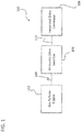
- the generator system 100 includes a gas turbine engine 102 that is configured to rotationally drive an integrated drive generator 106 through an accessory drive gearbox 104 mounted on the gas turbine engine 102.
- the accessory drive gearbox 104 is coupled to a spool 108 of the gas turbine engine 102, and the speed of the spool 108 varies throughout the entire operation of the gas turbine engine 108, depending on operational characteristics, such as high altitude cruising flight or take-off of the aircraft.
- An input shaft 110 is configured to transfer rotational energy to the integrated drive generator 106 from the accessory drive gearbox 104.
- FIG. 2 An example of an integrated drive generator 200 including a housing 202 is shown in FIG. 2 .
- the integrated drive generator 200 includes an input shaft 204 configured to receive rotational drive from an accessory drive gearbox (see FIG. 1 ).
- the rotational speed of the input shaft 204 varies depending upon the operation of the engine (see FIG. 1 ).
- a hydraulic unit 206 cooperates with a differential assembly 208 to convert the variable rotational speed from the input shaft 204 to a fixed rotational output speed that is transferred to a generator 210.
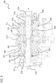
- the hydraulic unit 300 includes a variable displacement hydraulic pump 302 and a fixed displacement hydraulic motor 304.
- the variable displacement hydraulic pump 302 and the fixed displacement hydraulic motor 304 have respective cylinder blocks 306 and 308 which are arranged for rotation about a common axis A within housings 310, 311 on opposite sides of a stationary port plate 312 of the hydraulic unit 300.
- the port plate 312 is formed with one or more kidneys or apertures 314 through which hydraulic fluid communication between the pump 302 and the motor 304 is established during normal operation of the hydraulic unit 300.
- a biasing mechanism 316 resiliently biases the cylinder blocks 306, 308 in the direction of the port plate 312.
- the operation of the hydraulic unit 300 in an integrated drive generator involves transmission of torque from an engine of the aircraft to an input, which rotates an input shaft 318 of the hydraulic unit 300 about axis A.
- the cylinder block 306 of the pump 302 is connected to the input shaft 318 for rotation therewith.
- Pistons 320 within the cylinder block 306 of the pump 302 are displaced during rotation an amount which is a function of the setting of a variable swash plate or wobbler 322 of the pump 302.
- pistons 321 within the cylinder block 308 of the motor 304 are displaced during rotation an amount which is a function of the setting of a variable swash plate or wobbler 322 of the pump 302.
- the system may include nine pistons in each of the motor and the pump, and nine apertures may pass through the port plate.
- the number of apertures is not dependent on the number of pistons, and in some embodiments there may be five apertures when nine pistons are employed.
- the number of pistons and the number apertures may be varied without departing from the scope of the invention.
- Hydraulic fluid under pressure from the hydraulic pump 302 is delivered to the hydraulic motor 304 through the apertures 314 of port plate 312 for rotating the cylinder block 308 and an output shaft 324 to which the cylinder block 308 is fixedly connected.
- the swash plate or wobbler 326 of the motor 304 is fixedly configured so that an operating speed of the motor 304 is a function of a displacement of the pump 302.
- the rotary output from output shaft 324 is added to or subtracted from the rotary motion from the engine through a conventional differential gearing of an integrated drive generator for operating an electrical generator at a substantially constant rotational speed.
- the position of the variable wobbler 322 is adjusted in response to these detected speed variations for providing the necessary reduction or increase in the rotational speed for obtaining a desired constant output speed to the generator.
- the hydraulic unit 300 illustrated and described herein refers to the variable unit as a pump 302 and the fixed unit as a motor 304, hydraulic units having other configurations, such as where the variable unit functions as a motor and the hydraulic unit operates as a pump for example, are within the scope of the invention.
- the wobbler 322 is permitted to turn, rotate, tumble, and/or wobble about a retainer ball 328.
- the wobbler 322 is configured to wobble, etc., in part, as a result of the movement of the pistons 320, 321, respectively.
- a retainer ball 330 is configured to turn or rotate with respect to the wobbler 326.
- Each piston 320, 321 has a ball 332 (ball of piston 320 not labeled for clarity) on one end.
- the ball 332 of the pistons 320, 321 is retained within a slipper 334.
- the slipper 334 is retained by a slipper retainer 336.
- the slipper retainer 336 enables the slipper 334 to be held in contact with the wobbler 322, 326, thus enabling operational coupling and/or contact between the wobblers 322, 326 and the pistons 320, 321, respectively, of the pump 302 and the motor 304.
- FIGS. 4A-4C various views of an exemplary slipper retainer 400 in accordance with embodiments of the invention are shown.
- FIG. 4A is an isometric view of the slipper retainer 400
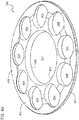
- FIG. 4B is a top plan view of the slipper retainer 400
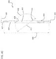
- FIG. 4C is a cross-sectional view of the slipper retainer 400 as viewed along the line A-A of FIG. 4B .
- slipper retainer 400 is formed of a circular body 401 that includes a central aperture 402 and a plurality of slipper apertures 404 that pass through the circular body 401.
- Central aperture 402 is configured to slidably engage with an exterior surface of a slipper retainer ball 328, 330.
- Each of the plurality of slipper apertures 404 is configured to engage and retain a slipper and a ball of a piston (see FIG. 3 ).
- FIG. 4B is a top plan view of the slipper retainer 400, showing the central aperture 402 with nine slipper apertures 404 distributed evenly about the slipper retainer 400.
- the slipper apertures 404 are located between a curved surface 408 of circular body 401 that defines the central aperture 402 and an outer edge or circumference 407 of the circular body 401 of the slipper retainer 400.
- nine slipper apertures 404 are shown in FIGS. 4A and 4B , those of skill in the art will appreciate that any number of slipper apertures may be used without departing from the scope of the invention. Further, those of skill in the art will appreciate that the number of slipper apertures should be configured to correspond to the number of slippers and pistons of the hydraulic unit into which the slipper retainers will be installed.
- the slipper retainer 400 has a slipper retainer diameter 406 that is about 2.240 inches (5.629 cm), with a variability of about +0.000 inches (0.000 cm) and about -0.005 inches (0.013 cm).
- the slipper retainer diameter 406 is the full diameter of the circular body 401 of slipper retainer 400.
- the circular body is configured with two thicknesses, as shown in FIGS. 4A and 4C .
- a first thickness 403 is at the exterior edge of the slipper retainer 400 and has a thickness of about 0.054 inches (0.137 cm) with a variability of about +/- 0.001 inches (0.003 cm).
- a second thickness 405 is positioned at the interior of circular body 401 and surrounds the central aperture 402. The second thickness has a thickness of about 0.108 inches (0.274 cm) with a variability of about +/- 0.003 inches (0.008 cm).
- the central aperture 402 has an arcuate or curved surface 408, in the axial direction of the slipper retainer 400, as shown in FIG. 4C .
- the curved surface 408 is configured to engage with an exterior surface of a retainer ball (see FIG. 3 , retainer ball 328).
- the curvature of the curved surface 408 is defined by a circle or sphere 410 that is located or centered at point 412.
- Point 412 is located at a distance of about 0.209 inches (0.531 cm) with a variability of about +0.000 inches (0.000 cm) and about -0.003 inches (0.008 cm) from a back surface 414 of slipper retainer 400.
- the sphere 410 has a diameter 416 of about 1.1090 inches (2.8168 cm) with a variability of about +0.0010 inches (0.0025 cm) and about -0.0000 inches (0.0000 cm). As noted, the circumference of sphere 410 defines the curved surface 408 of the circular body 401 about the central aperture 402 of slipper retainer 400.
- each slipper aperture 404 is located about 0.820 inches from the center of the slipper retainer 400. That is, in a radial direction, a slipper aperture center point 418 of the slipper aperture 404 is located a radial distance 420 that is about 0.820 inches (2.083 cm) from a central aperture center point 422. Each slipper aperture 404 has a diameter 424 that is about 0.464 inches (1.179 cm) with a variability of about +/- 0.002 inches (0.005 cm).
- FIGS. 4A-4C display certain dimensions not discussed above, but are pertinent and relate to various embodiments and/or alternatives of the invention disclosed herein. Thus, the dimensions detailed on the figures, but not discussed above, are incorporated into this specification.
- slipper retainers configured in accordance with embodiments of the invention appropriately fit within and operate with specific hydraulic units. Further, advantageously, failure and damage is less likely to occur and efficiency is increased within specific hydraulic units when slipper retainers in accordance with embodiments of the invention are employed.
Landscapes
- Engineering & Computer Science (AREA)
- Mechanical Engineering (AREA)
- General Engineering & Computer Science (AREA)
- Chemical & Material Sciences (AREA)
- Combustion & Propulsion (AREA)
- Reciprocating Pumps (AREA)
Claims (12)
- Gleitschuhhalter (400) zur Installation in einer Hydraulikeinheit, wobei der Gleitschuhhalter (400) Folgendes umfasst:einen kreisförmigen Körper, der eine Rückfläche und eine Außenkante aufweist, wobei der kreisförmige Körper einen Durchmesser von 5,629 cm (2,240 Zoll) definiert;eine zentrale Öffnung (402) durch eine Mitte des kreisförmigen Körpers (401), wobei der kreisförmige Körper eine gekrümmte Fläche aufweist, die eine Kante der zentralen Öffnung definiert, wobei die gekrümmte Fläche durch eine Kugel definiert ist, die an einem Punkt zentriert ist, der sich in einem Abstand von 0,531 cm (0,209 Zoll) zu der Rückfläche des Körpers befindet;eine Vielzahl von Gleitschuhöffnungen (404), die sich zwischen der gekrümmten Fläche des kreisförmigen Körpers und der Außenkante des kreisförmigen Körpers befinden, wobei jede Gleitschuhöffnung der Vielzahl von Gleitschuhöffnungen einen Durchmesser von 1,179 cm (0,464 Zoll) aufweist, und wobei der kreisförmige Körper (401) eine erste Dicke proximal zu der zentralen Öffnung und eine zweite Dicke proximal zu der Außenkante definiert.
- Gleitschuhhalter nach Anspruch 1, wobei der Durchmesser des kreisförmigen Körpers (401) eine Variabilität von 0,000 cm (+0,000 Zoll) und 0,013 cm (-0,005 Zoll) aufweist.
- Gleitschuhhalter nach einem der vorhergehenden Ansprüche, wobei der Abstand von dem Punkt der Mitte der Kugel eine Variabilität von 0,000 cm (+0,000 Zoll) und 0,008 cm (-0,003 Zoll) aufweist.
- Gleitschuhhalter nach einem der vorhergehenden Ansprüche, wobei der Durchmesser von jeder der Vielzahl von Gleitschuhöffnungen (404) eine Variabilität von 0,005 cm (+/-0,002 Zoll) aufweist.
- Gleitschuhhalter nach einem der vorhergehenden Ansprüche, wobei die Vielzahl von Gleitschuhöffnungen (404) neun Gleitschuhöffnungen definiert.
- Gleitschuhhalter nach einem der vorhergehenden Ansprüche, wobei die erste Dicke 0,274 cm (0,108 Zoll) entspricht.
- Gleitschuhhalter nach einem der vorhergehenden Ansprüche, wobei die erste Dicke eine Variabilität von 0,008 cm (+/-0,003 Zoll) aufweist.
- Gleitschuhhalter nach einem der vorhergehenden Ansprüche, wobei die zweite Dicke 0,137 cm (0,054 Zoll) entspricht.
- Gleitschuhhalter nach einem der vorhergehenden Ansprüche, wobei die zweite Dicke eine Variabilität von 0,003 cm (+/-0,001 Zoll) aufweist.
- Gleitschuhhalter nach einem der vorhergehenden Ansprüche, wobei die Kugel, welche die gekrümmte Fläche definiert, einen Durchmesser von 2,8168 cm (1,1090 Zoll) aufweist.
- Gleitschuhhalter nach Anspruch 10, wobei der Durchmesser der Kugel eine Variabilität von 0,0025 cm (+0,0010 Zoll) und 0,0000 cm (-0,0000 Zoll) aufweist.
- Gleitschuhhalter nach einem der vorhergehenden Ansprüche, wobei sich jede der Vielzahl von Gleitschuhöffnungen 404 radial in einem Abstand von 2,083 cm (0,820 Zoll) zu einer Mitte des kreisförmigen Körpers befindet.
Applications Claiming Priority (1)
| Application Number | Priority Date | Filing Date | Title |
|---|---|---|---|
| US14/598,291 US9863408B2 (en) | 2015-01-16 | 2015-01-16 | Slipper retainer for hydraulic unit |
Publications (2)
| Publication Number | Publication Date |
|---|---|
| EP3048302A1 EP3048302A1 (de) | 2016-07-27 |
| EP3048302B1 true EP3048302B1 (de) | 2018-04-18 |
Family
ID=55182218
Family Applications (1)
| Application Number | Title | Priority Date | Filing Date |
|---|---|---|---|
| EP16151672.9A Active EP3048302B1 (de) | 2015-01-16 | 2016-01-18 | Gleitschuhhalter für hydraulikeinheit |
Country Status (2)
| Country | Link |
|---|---|
| US (1) | US9863408B2 (de) |
| EP (1) | EP3048302B1 (de) |
Families Citing this family (2)
| Publication number | Priority date | Publication date | Assignee | Title |
|---|---|---|---|---|
| US10422324B2 (en) * | 2017-11-22 | 2019-09-24 | Hamilton Sundstrand Corporation | Wear ring for integrated drive generator |
| DE102023206128A1 (de) * | 2023-06-29 | 2025-01-02 | Robert Bosch Gesellschaft mit beschränkter Haftung | Axialkolbenmaschine mit Rückzugsplatte für hohe Drehzahlen |
Family Cites Families (18)
| Publication number | Priority date | Publication date | Assignee | Title |
|---|---|---|---|---|
| US3303794A (en) * | 1967-02-14 | Piston return mechanism | ||
| US3292553A (en) * | 1963-12-30 | 1966-12-20 | Sunstrand Corp | Piston return mechanism |
| US3382793A (en) * | 1965-08-09 | 1968-05-14 | Sundstrand Corp | Axial piston hydraulic unit |
| DE1945434A1 (de) * | 1969-09-08 | 1971-03-11 | Linde Ag | Axialkolbenmaschine |
| DE3222210A1 (de) | 1982-06-12 | 1983-12-15 | Linde Ag, 6200 Wiesbaden | Schraegscheiben-axialkolbenmaschine |
| JP2963218B2 (ja) * | 1991-01-28 | 1999-10-18 | 本田技研工業株式会社 | 斜板プランジャ式油圧装置 |
| US5704272A (en) | 1996-08-26 | 1998-01-06 | Sundstrand Corporation | Axial piston energy converting device |
| US5862704A (en) * | 1996-11-27 | 1999-01-26 | Caterpillar Inc. | Retainer mechanism for an axial piston machine |
| JPH10266953A (ja) * | 1997-03-25 | 1998-10-06 | Zexel Corp | 斜板式圧縮機 |
| US6352017B1 (en) * | 1999-01-21 | 2002-03-05 | Samjoo Machinery Co., Ltd. | Hydraulic pump |
| DE10300070A1 (de) | 2002-11-15 | 2004-06-03 | Brueninghaus Hydromatik Gmbh | Axialkolbenmaschine, Rückzugplatte und Verfahren zum Herstellen einer Rückzugplatte |
| DE102006042677A1 (de) | 2006-07-10 | 2008-01-17 | Robert Bosch Gmbh | Axialkolbenmaschine mit einer Ansatzscheibe an einer Rückhaltescheibe, entsprechende Rückhaltescheibe und entsprechende Ansatzscheibe |
| DE102007049393A1 (de) * | 2007-10-15 | 2009-04-16 | Linde Material Handling Gmbh | Axialkolbenmaschine |
| DE102010036199B4 (de) | 2010-09-02 | 2021-11-18 | Linde Hydraulics Gmbh & Co. Kg | Axialkolbenmaschine mit verringerter Verlustleistung durch Verwendung geeigneter Dichtmittel im Bereich der Schrägscheibenausnehmung |
| JP4934749B1 (ja) | 2011-02-23 | 2012-05-16 | 株式会社小松製作所 | 可変容量型油圧ポンプ・モータ |
| BR112014013732A8 (pt) * | 2011-12-07 | 2017-06-13 | Ecothermics Corp | compressor/bomba de alta pressão de pistão axial |
| JP6326408B2 (ja) * | 2013-03-29 | 2018-05-16 | Kyb株式会社 | 対向式斜板型液圧回転機 |
| DE102013210416A1 (de) * | 2013-06-05 | 2014-12-11 | Robert Bosch Gmbh | Hydrostatische Axialkolbenmaschine und Rückhalteplatte |
-
2015
- 2015-01-16 US US14/598,291 patent/US9863408B2/en active Active
-
2016
- 2016-01-18 EP EP16151672.9A patent/EP3048302B1/de active Active
Non-Patent Citations (1)
| Title |
|---|
| None * |
Also Published As
| Publication number | Publication date |
|---|---|
| EP3048302A1 (de) | 2016-07-27 |
| US9863408B2 (en) | 2018-01-09 |
| US20160208784A1 (en) | 2016-07-21 |
Similar Documents
| Publication | Publication Date | Title |
|---|---|---|
| EP2541741A1 (de) | Wellengetriebener doppelstator-mehrgeschwindigkeitsmotor mit krümmungen von gleicher breite | |
| US20110314963A1 (en) | Controllable constant speed gearbox | |
| EP3023616B1 (de) | Variable welle für hydraulikeinheit | |
| EP3048302B1 (de) | Gleitschuhhalter für hydraulikeinheit | |
| EP3070330A1 (de) | Zylinderblockanordnung für hydraulikaggregat | |
| EP3045721A1 (de) | Variables taumelelement für hydraulikeinheit | |
| US9435378B1 (en) | Roller bearing outer race for hydraulic unit | |
| EP3023651B1 (de) | Festwelle für hydraulikeinheit | |
| US9714702B2 (en) | Variable coaxial shaft for hydraulic unit | |
| EP3061965B1 (de) | Wälzlageraussenring einer hydraulikeinheit | |
| EP3045720B1 (de) | Gleitschuhhalterkugel für hydraulikeinheit | |
| US9845679B2 (en) | Port plate assembly for hydraulic unit | |
| EP3509199B1 (de) | Hauptgeneratorstatorhülse für integrierten antriebsgenerator | |
| EP3073111A1 (de) | Kolben- und gleitschuhanordnung für eine hydraulikbaugruppe | |
| US20190211871A1 (en) | Fixed block shaft inner bearing race for integrated drive generator | |
| US10707792B2 (en) | Variable wobbler plate for integrated drive generator | |
| EP3045722B1 (de) | Fester wobbler für hydraulikbaugruppe | |
| US10422324B2 (en) | Wear ring for integrated drive generator | |
| EP3511595B1 (de) | Variable blockwelle für einen integrierten antriebsgenerator | |
| EP3519293B1 (de) | Drehschieberlenkgetriebe |
Legal Events
| Date | Code | Title | Description |
|---|---|---|---|
| PUAI | Public reference made under article 153(3) epc to a published international application that has entered the european phase |
Free format text: ORIGINAL CODE: 0009012 |
|
| AK | Designated contracting states |
Kind code of ref document: A1 Designated state(s): AL AT BE BG CH CY CZ DE DK EE ES FI FR GB GR HR HU IE IS IT LI LT LU LV MC MK MT NL NO PL PT RO RS SE SI SK SM TR |
|
| AX | Request for extension of the european patent |
Extension state: BA ME |
|
| STAA | Information on the status of an ep patent application or granted ep patent |
Free format text: STATUS: REQUEST FOR EXAMINATION WAS MADE |
|
| 17P | Request for examination filed |
Effective date: 20170126 |
|
| RBV | Designated contracting states (corrected) |
Designated state(s): AL AT BE BG CH CY CZ DE DK EE ES FI FR GB GR HR HU IE IS IT LI LT LU LV MC MK MT NL NO PL PT RO RS SE SI SK SM TR |
|
| GRAP | Despatch of communication of intention to grant a patent |
Free format text: ORIGINAL CODE: EPIDOSNIGR1 |
|
| STAA | Information on the status of an ep patent application or granted ep patent |
Free format text: STATUS: GRANT OF PATENT IS INTENDED |
|
| INTG | Intention to grant announced |
Effective date: 20171102 |
|
| GRAS | Grant fee paid |
Free format text: ORIGINAL CODE: EPIDOSNIGR3 |
|
| GRAA | (expected) grant |
Free format text: ORIGINAL CODE: 0009210 |
|
| STAA | Information on the status of an ep patent application or granted ep patent |
Free format text: STATUS: THE PATENT HAS BEEN GRANTED |
|
| AK | Designated contracting states |
Kind code of ref document: B1 Designated state(s): AL AT BE BG CH CY CZ DE DK EE ES FI FR GB GR HR HU IE IS IT LI LT LU LV MC MK MT NL NO PL PT RO RS SE SI SK SM TR |
|
| REG | Reference to a national code |
Ref country code: GB Ref legal event code: FG4D |
|
| REG | Reference to a national code |
Ref country code: CH Ref legal event code: EP |
|
| REG | Reference to a national code |
Ref country code: AT Ref legal event code: REF Ref document number: 990780 Country of ref document: AT Kind code of ref document: T Effective date: 20180515 |
|
| REG | Reference to a national code |
Ref country code: IE Ref legal event code: FG4D |
|
| REG | Reference to a national code |
Ref country code: DE Ref legal event code: R096 Ref document number: 602016002412 Country of ref document: DE |
|
| REG | Reference to a national code |
Ref country code: NL Ref legal event code: MP Effective date: 20180418 |
|
| REG | Reference to a national code |
Ref country code: LT Ref legal event code: MG4D |
|
| PG25 | Lapsed in a contracting state [announced via postgrant information from national office to epo] |
Ref country code: NL Free format text: LAPSE BECAUSE OF FAILURE TO SUBMIT A TRANSLATION OF THE DESCRIPTION OR TO PAY THE FEE WITHIN THE PRESCRIBED TIME-LIMIT Effective date: 20180418 |
|
| PG25 | Lapsed in a contracting state [announced via postgrant information from national office to epo] |
Ref country code: LT Free format text: LAPSE BECAUSE OF FAILURE TO SUBMIT A TRANSLATION OF THE DESCRIPTION OR TO PAY THE FEE WITHIN THE PRESCRIBED TIME-LIMIT Effective date: 20180418 Ref country code: FI Free format text: LAPSE BECAUSE OF FAILURE TO SUBMIT A TRANSLATION OF THE DESCRIPTION OR TO PAY THE FEE WITHIN THE PRESCRIBED TIME-LIMIT Effective date: 20180418 Ref country code: BG Free format text: LAPSE BECAUSE OF FAILURE TO SUBMIT A TRANSLATION OF THE DESCRIPTION OR TO PAY THE FEE WITHIN THE PRESCRIBED TIME-LIMIT Effective date: 20180718 Ref country code: PL Free format text: LAPSE BECAUSE OF FAILURE TO SUBMIT A TRANSLATION OF THE DESCRIPTION OR TO PAY THE FEE WITHIN THE PRESCRIBED TIME-LIMIT Effective date: 20180418 Ref country code: NO Free format text: LAPSE BECAUSE OF FAILURE TO SUBMIT A TRANSLATION OF THE DESCRIPTION OR TO PAY THE FEE WITHIN THE PRESCRIBED TIME-LIMIT Effective date: 20180718 Ref country code: AL Free format text: LAPSE BECAUSE OF FAILURE TO SUBMIT A TRANSLATION OF THE DESCRIPTION OR TO PAY THE FEE WITHIN THE PRESCRIBED TIME-LIMIT Effective date: 20180418 Ref country code: SE Free format text: LAPSE BECAUSE OF FAILURE TO SUBMIT A TRANSLATION OF THE DESCRIPTION OR TO PAY THE FEE WITHIN THE PRESCRIBED TIME-LIMIT Effective date: 20180418 Ref country code: ES Free format text: LAPSE BECAUSE OF FAILURE TO SUBMIT A TRANSLATION OF THE DESCRIPTION OR TO PAY THE FEE WITHIN THE PRESCRIBED TIME-LIMIT Effective date: 20180418 |
|
| PG25 | Lapsed in a contracting state [announced via postgrant information from national office to epo] |
Ref country code: GR Free format text: LAPSE BECAUSE OF FAILURE TO SUBMIT A TRANSLATION OF THE DESCRIPTION OR TO PAY THE FEE WITHIN THE PRESCRIBED TIME-LIMIT Effective date: 20180719 Ref country code: HR Free format text: LAPSE BECAUSE OF FAILURE TO SUBMIT A TRANSLATION OF THE DESCRIPTION OR TO PAY THE FEE WITHIN THE PRESCRIBED TIME-LIMIT Effective date: 20180418 Ref country code: RS Free format text: LAPSE BECAUSE OF FAILURE TO SUBMIT A TRANSLATION OF THE DESCRIPTION OR TO PAY THE FEE WITHIN THE PRESCRIBED TIME-LIMIT Effective date: 20180418 Ref country code: LV Free format text: LAPSE BECAUSE OF FAILURE TO SUBMIT A TRANSLATION OF THE DESCRIPTION OR TO PAY THE FEE WITHIN THE PRESCRIBED TIME-LIMIT Effective date: 20180418 |
|
| REG | Reference to a national code |
Ref country code: AT Ref legal event code: MK05 Ref document number: 990780 Country of ref document: AT Kind code of ref document: T Effective date: 20180418 |
|
| PG25 | Lapsed in a contracting state [announced via postgrant information from national office to epo] |
Ref country code: PT Free format text: LAPSE BECAUSE OF FAILURE TO SUBMIT A TRANSLATION OF THE DESCRIPTION OR TO PAY THE FEE WITHIN THE PRESCRIBED TIME-LIMIT Effective date: 20180820 |
|
| REG | Reference to a national code |
Ref country code: DE Ref legal event code: R097 Ref document number: 602016002412 Country of ref document: DE |
|
| PG25 | Lapsed in a contracting state [announced via postgrant information from national office to epo] |
Ref country code: AT Free format text: LAPSE BECAUSE OF FAILURE TO SUBMIT A TRANSLATION OF THE DESCRIPTION OR TO PAY THE FEE WITHIN THE PRESCRIBED TIME-LIMIT Effective date: 20180418 Ref country code: DK Free format text: LAPSE BECAUSE OF FAILURE TO SUBMIT A TRANSLATION OF THE DESCRIPTION OR TO PAY THE FEE WITHIN THE PRESCRIBED TIME-LIMIT Effective date: 20180418 Ref country code: EE Free format text: LAPSE BECAUSE OF FAILURE TO SUBMIT A TRANSLATION OF THE DESCRIPTION OR TO PAY THE FEE WITHIN THE PRESCRIBED TIME-LIMIT Effective date: 20180418 Ref country code: RO Free format text: LAPSE BECAUSE OF FAILURE TO SUBMIT A TRANSLATION OF THE DESCRIPTION OR TO PAY THE FEE WITHIN THE PRESCRIBED TIME-LIMIT Effective date: 20180418 Ref country code: SK Free format text: LAPSE BECAUSE OF FAILURE TO SUBMIT A TRANSLATION OF THE DESCRIPTION OR TO PAY THE FEE WITHIN THE PRESCRIBED TIME-LIMIT Effective date: 20180418 Ref country code: CZ Free format text: LAPSE BECAUSE OF FAILURE TO SUBMIT A TRANSLATION OF THE DESCRIPTION OR TO PAY THE FEE WITHIN THE PRESCRIBED TIME-LIMIT Effective date: 20180418 |
|
| PLBE | No opposition filed within time limit |
Free format text: ORIGINAL CODE: 0009261 |
|
| STAA | Information on the status of an ep patent application or granted ep patent |
Free format text: STATUS: NO OPPOSITION FILED WITHIN TIME LIMIT |
|
| PG25 | Lapsed in a contracting state [announced via postgrant information from national office to epo] |
Ref country code: SM Free format text: LAPSE BECAUSE OF FAILURE TO SUBMIT A TRANSLATION OF THE DESCRIPTION OR TO PAY THE FEE WITHIN THE PRESCRIBED TIME-LIMIT Effective date: 20180418 Ref country code: IT Free format text: LAPSE BECAUSE OF FAILURE TO SUBMIT A TRANSLATION OF THE DESCRIPTION OR TO PAY THE FEE WITHIN THE PRESCRIBED TIME-LIMIT Effective date: 20180418 |
|
| 26N | No opposition filed |
Effective date: 20190121 |
|
| PG25 | Lapsed in a contracting state [announced via postgrant information from national office to epo] |
Ref country code: SI Free format text: LAPSE BECAUSE OF FAILURE TO SUBMIT A TRANSLATION OF THE DESCRIPTION OR TO PAY THE FEE WITHIN THE PRESCRIBED TIME-LIMIT Effective date: 20180418 |
|
| REG | Reference to a national code |
Ref country code: DE Ref legal event code: R119 Ref document number: 602016002412 Country of ref document: DE |
|
| PG25 | Lapsed in a contracting state [announced via postgrant information from national office to epo] |
Ref country code: MC Free format text: LAPSE BECAUSE OF FAILURE TO SUBMIT A TRANSLATION OF THE DESCRIPTION OR TO PAY THE FEE WITHIN THE PRESCRIBED TIME-LIMIT Effective date: 20180418 |
|
| REG | Reference to a national code |
Ref country code: CH Ref legal event code: PL |
|
| PG25 | Lapsed in a contracting state [announced via postgrant information from national office to epo] |
Ref country code: LU Free format text: LAPSE BECAUSE OF NON-PAYMENT OF DUE FEES Effective date: 20190118 |
|
| REG | Reference to a national code |
Ref country code: BE Ref legal event code: MM Effective date: 20190131 |
|
| REG | Reference to a national code |
Ref country code: IE Ref legal event code: MM4A |
|
| PG25 | Lapsed in a contracting state [announced via postgrant information from national office to epo] |
Ref country code: DE Free format text: LAPSE BECAUSE OF NON-PAYMENT OF DUE FEES Effective date: 20190801 |
|
| PG25 | Lapsed in a contracting state [announced via postgrant information from national office to epo] |
Ref country code: BE Free format text: LAPSE BECAUSE OF NON-PAYMENT OF DUE FEES Effective date: 20190131 |
|
| PG25 | Lapsed in a contracting state [announced via postgrant information from national office to epo] |
Ref country code: LI Free format text: LAPSE BECAUSE OF NON-PAYMENT OF DUE FEES Effective date: 20190131 Ref country code: CH Free format text: LAPSE BECAUSE OF NON-PAYMENT OF DUE FEES Effective date: 20190131 |
|
| PG25 | Lapsed in a contracting state [announced via postgrant information from national office to epo] |
Ref country code: IE Free format text: LAPSE BECAUSE OF NON-PAYMENT OF DUE FEES Effective date: 20190118 |
|
| PG25 | Lapsed in a contracting state [announced via postgrant information from national office to epo] |
Ref country code: TR Free format text: LAPSE BECAUSE OF FAILURE TO SUBMIT A TRANSLATION OF THE DESCRIPTION OR TO PAY THE FEE WITHIN THE PRESCRIBED TIME-LIMIT Effective date: 20180418 |
|
| PG25 | Lapsed in a contracting state [announced via postgrant information from national office to epo] |
Ref country code: MT Free format text: LAPSE BECAUSE OF NON-PAYMENT OF DUE FEES Effective date: 20190118 |
|
| PG25 | Lapsed in a contracting state [announced via postgrant information from national office to epo] |
Ref country code: CY Free format text: LAPSE BECAUSE OF FAILURE TO SUBMIT A TRANSLATION OF THE DESCRIPTION OR TO PAY THE FEE WITHIN THE PRESCRIBED TIME-LIMIT Effective date: 20180418 |
|
| PG25 | Lapsed in a contracting state [announced via postgrant information from national office to epo] |
Ref country code: IS Free format text: LAPSE BECAUSE OF FAILURE TO SUBMIT A TRANSLATION OF THE DESCRIPTION OR TO PAY THE FEE WITHIN THE PRESCRIBED TIME-LIMIT Effective date: 20180818 |
|
| PG25 | Lapsed in a contracting state [announced via postgrant information from national office to epo] |
Ref country code: HU Free format text: LAPSE BECAUSE OF FAILURE TO SUBMIT A TRANSLATION OF THE DESCRIPTION OR TO PAY THE FEE WITHIN THE PRESCRIBED TIME-LIMIT; INVALID AB INITIO Effective date: 20160118 |
|
| PG25 | Lapsed in a contracting state [announced via postgrant information from national office to epo] |
Ref country code: MK Free format text: LAPSE BECAUSE OF FAILURE TO SUBMIT A TRANSLATION OF THE DESCRIPTION OR TO PAY THE FEE WITHIN THE PRESCRIBED TIME-LIMIT Effective date: 20180418 |
|
| P01 | Opt-out of the competence of the unified patent court (upc) registered |
Effective date: 20230522 |
|
| PGFP | Annual fee paid to national office [announced via postgrant information from national office to epo] |
Ref country code: GB Payment date: 20251220 Year of fee payment: 11 |
|
| PGFP | Annual fee paid to national office [announced via postgrant information from national office to epo] |
Ref country code: FR Payment date: 20251217 Year of fee payment: 11 |