EP3046337A1 - Hochtonlautsprecher und verfahren zur erzielung eines omnidirektionalen hochtonschallfeldes - Google Patents
Hochtonlautsprecher und verfahren zur erzielung eines omnidirektionalen hochtonschallfeldes Download PDFInfo
- Publication number
- EP3046337A1 EP3046337A1 EP15810779.7A EP15810779A EP3046337A1 EP 3046337 A1 EP3046337 A1 EP 3046337A1 EP 15810779 A EP15810779 A EP 15810779A EP 3046337 A1 EP3046337 A1 EP 3046337A1
- Authority
- EP
- European Patent Office
- Prior art keywords
- horns
- sound track
- tweeter unit
- tweeter
- unit
- Prior art date
- Legal status (The legal status is an assumption and is not a legal conclusion. Google has not performed a legal analysis and makes no representation as to the accuracy of the status listed.)
- Granted
Links
Images




Classifications
-
- H—ELECTRICITY
- H04—ELECTRIC COMMUNICATION TECHNIQUE
- H04R—LOUDSPEAKERS, MICROPHONES, GRAMOPHONE PICK-UPS OR LIKE ACOUSTIC ELECTROMECHANICAL TRANSDUCERS; ELECTRIC HEARING AIDS; PUBLIC ADDRESS SYSTEMS
- H04R5/00—Stereophonic arrangements
- H04R5/02—Spatial or constructional arrangements of loudspeakers
-
- H—ELECTRICITY
- H04—ELECTRIC COMMUNICATION TECHNIQUE
- H04R—LOUDSPEAKERS, MICROPHONES, GRAMOPHONE PICK-UPS OR LIKE ACOUSTIC ELECTROMECHANICAL TRANSDUCERS; ELECTRIC HEARING AIDS; PUBLIC ADDRESS SYSTEMS
- H04R1/00—Details of transducers, loudspeakers or microphones
- H04R1/20—Arrangements for obtaining desired frequency or directional characteristics
- H04R1/32—Arrangements for obtaining desired frequency or directional characteristics for obtaining desired directional characteristic only
- H04R1/323—Arrangements for obtaining desired frequency or directional characteristics for obtaining desired directional characteristic only for loudspeakers
-
- H—ELECTRICITY
- H04—ELECTRIC COMMUNICATION TECHNIQUE
- H04R—LOUDSPEAKERS, MICROPHONES, GRAMOPHONE PICK-UPS OR LIKE ACOUSTIC ELECTROMECHANICAL TRANSDUCERS; ELECTRIC HEARING AIDS; PUBLIC ADDRESS SYSTEMS
- H04R1/00—Details of transducers, loudspeakers or microphones
- H04R1/20—Arrangements for obtaining desired frequency or directional characteristics
- H04R1/32—Arrangements for obtaining desired frequency or directional characteristics for obtaining desired directional characteristic only
- H04R1/40—Arrangements for obtaining desired frequency or directional characteristics for obtaining desired directional characteristic only by combining a number of identical transducers
- H04R1/403—Arrangements for obtaining desired frequency or directional characteristics for obtaining desired directional characteristic only by combining a number of identical transducers loud-speakers
-
- H—ELECTRICITY
- H04—ELECTRIC COMMUNICATION TECHNIQUE
- H04R—LOUDSPEAKERS, MICROPHONES, GRAMOPHONE PICK-UPS OR LIKE ACOUSTIC ELECTROMECHANICAL TRANSDUCERS; ELECTRIC HEARING AIDS; PUBLIC ADDRESS SYSTEMS
- H04R31/00—Apparatus or processes specially adapted for the manufacture of transducers or diaphragms therefor
- H04R31/006—Interconnection of transducer parts
-
- H—ELECTRICITY
- H04—ELECTRIC COMMUNICATION TECHNIQUE
- H04R—LOUDSPEAKERS, MICROPHONES, GRAMOPHONE PICK-UPS OR LIKE ACOUSTIC ELECTROMECHANICAL TRANSDUCERS; ELECTRIC HEARING AIDS; PUBLIC ADDRESS SYSTEMS
- H04R1/00—Details of transducers, loudspeakers or microphones
- H04R1/20—Arrangements for obtaining desired frequency or directional characteristics
- H04R1/32—Arrangements for obtaining desired frequency or directional characteristics for obtaining desired directional characteristic only
- H04R1/34—Arrangements for obtaining desired frequency or directional characteristics for obtaining desired directional characteristic only by using a single transducer with sound reflecting, diffracting, directing or guiding means
- H04R1/345—Arrangements for obtaining desired frequency or directional characteristics for obtaining desired directional characteristic only by using a single transducer with sound reflecting, diffracting, directing or guiding means for loudspeakers
-
- H—ELECTRICITY
- H04—ELECTRIC COMMUNICATION TECHNIQUE
- H04R—LOUDSPEAKERS, MICROPHONES, GRAMOPHONE PICK-UPS OR LIKE ACOUSTIC ELECTROMECHANICAL TRANSDUCERS; ELECTRIC HEARING AIDS; PUBLIC ADDRESS SYSTEMS
- H04R2205/00—Details of stereophonic arrangements covered by H04R5/00 but not provided for in any of its subgroups
- H04R2205/022—Plurality of transducers corresponding to a plurality of sound channels in each earpiece of headphones or in a single enclosure
Definitions
- the invention relates to acoustic technology, in particular to a tweeter and a method for realizing omnidirectional high pitch sound field.
- the invention provides a tweeter and a method for realizing omnidirectional high pitch sound field to solve or at least partially solve the above problems.
- the technical solution of the embodiments of the present invention is realized as follows:
- the plurality of horns are disposed evenly on a whole plane, wherein the number of the horns of the left sound track is two or more, and correspondingly, the number of the horns of the right sound track is also above two or more.
- the tweeter also comprises: a first sealing foam matching the first tweeter unit, a second sealing foam matching the second tweeter unit, wherein the first sealing foam can surround the first tweeter unit without contacting the diaphragm of the first tweeter unit, and the second sealing foam can surround the second tweeter unit without contacting the diaphragm of the second tweeter unit; the first tweeter unit and the second tweeter unit are assembled on the radiation structure via the first sealing foam and the second sealing foam, respectively.
- the tweeter also comprises: a first phase cone and a second phase cone; the first phase cone is fixed by a support frame symmetrically disposed on the horns of the left sound track and located in front of the diaphragm of the first tweeter unit; and the second phase cone is fixed by a support frame symmetrically disposed on the horns of the right sound track and located in front of the diaphragm of the second tweeter unit.
- a central axis of the first tweeter unit coincides with a central axis of the second tweeter unit, or a central axis of the first tweeter unit does not coincide with a central axis of the second tweeter unit.
- the horns of the left sound track and the horns of the right sound track are symmetrical in position.
- the horns of the left sound track and the horns of the right sound track are not symmetrical in position.
- the first tweeter unit when the central axis of the first tweeter unit does not coincide with the central axis of the second tweeter unit, the first tweeter unit partially overlaps the second tweeter unit in the axial direction.
- the tweeter provided in the embodiments of the invention has advantages of simple structure, small volume and low cost.
- the tweeter By disposing the horns of the left sound track and the horns of the right sound track at intervals, the tweeter has stereo effect.
- the sound wave emitted by the horns can cover horizontal 360°, effectively solving the problem in the acoustic structure of the prior art that 360°surround stereo cannot be realized under the general request of miniaturization and low cost.
- the embodiments of the invention provide a method for realizing omnidirectional high pitch sound field, comprising:
- the plurality of horns evenly on a whole plane, wherein the number of the horns of the left sound track is two or more, and correspondingly, the number of the horns of the right sound track is also two or more.
- first sealing foam matching the first tweeter unit, and a second sealing foam matching the second tweeter unit
- first sealing foam can surround the first tweeter unit without contacting the diaphragm of the first tweeter unit
- second sealing foam can surround the second tweeter unit without contacting the diaphragm of the second tweeter unit
- Assembling the first tweeter unit and the second tweeter unit on the radiation structure respectively comprises:
- the above method further comprises:
- the central axis of the first tweeter unit coincides with the central axis of the second tweeter unit, or the central axis of the first tweeter unit does not coincide with the central axis of the second tweeter unit.
- the central axis of the first tweeter unit coincides with the central axis of the second tweeter unit, dispose the horns of the left sound track and the horns of the right sound track to be symmetrical in position.
- the central axis of the first tweeter unit does not coincide with the central axis of the second tweeter unit, dispose the horns of the left sound track and the horns of the right sound track to be not symmetrical in position, or dispose the first tweeter unit to partially overlap the second tweeter unit in the axial direction.
- the method for realizing omnidirectional high pitch sound field provided by the embodiments of the present invention, by disposing the horns of the left sound track and the horns of the right sound track at intervals, stereo effect is realized; and by disposing all of the horns evenly in a whole plane, the sound wave emitted by the horns can cover horizontal 360°, effectively solving the problem in the acoustic structure of the prior art that 360°surround stereo cannot be realized under the general request of miniaturization and low cost.
- the tweeter provided in an embodiment of the present invention comprises: a first tweeter unit 11 corresponding to the left sound track, a second tweeter unit 12 corresponding to the right sound track, a radiation structure 13 formed by a plurality of horns (horns 141, horns 142), wherein the radiation structure 13 may be formed integrally or may be made up of separated components, the radiation structure 13 in this embodiment is formed integrally.
- the first tweeter unit 11 may also be used in the right sound track and the second tweeter unit 12 may also be used in the left sound track.
- Fig. 2 it shows a perspective view of the assembly after the components in Fig. 1 have been assembled.
- the number of the horns of the left sound track is the same as the number of the horns of the right sound track, and the horns 141 of the left sound track and the horns 142 of the right sound track are disposed at intervals via partition walls, that is, the horns 141 of the left sound track are disposed adjacent the horns 142 of the right sound track, and the thickness of the partition walls between the horns can be adjusted according to actual needs.
- Fig.3 it is a section view of the assembly after the components in Fig. 1 have been assembled.
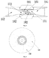
- the first tweeter unit 11 and the second tweeter unit 12 are assembled on the radiation structure 13 respectively, a diaphragm 181 of the first tweeter unit 11 and a diaphragm 182 of the second tweeter unit 12 are disposed oppositely, each of the horns 141 of the left sound track is provided with a first sound track opening 171 only for the first tweeter unit 11, sound waves of the left sound track radiated by the first tweeter unit 11 enter the horns 141 of the left sound track along the first sound track openings 171, and finally spread from ventilation holes of the horns 141 to the space along the horns 141 of the left sound track; each of the horns 142 of the right sound track is provided with a second sound track opening 172 only for the second tweeter unit 12, sound waves of the right sound track radiated by the second tweeter unit 12 enter the horns 142 of the right sound track along the second sound
- the two tweeter units (11, 12) and the radiation structure 13 are usually made from a material with great hardness. If they are assembled directly, there would be gaps, and the sound emitted from the two tweeter units may enter the radiation structure 13 through the gaps, thereby affecting the sound quality.
- a structure of sealing foam made from a flexible material is used for sealing the gaps generated by directly assembling the two tweeter units and the radiation structure, which not only realizes non-rigid connection by the foams but also guarantees the sound quality of the audio equipment.
- the first tweeter unit 11 and the second tweeter unit 12 are assembled on the radiation structure 13 via the first sealing foam 151 and the second sealing foam 152, respectively; the first sealing foam 151 matches the first tweeter unit 11, the second sealing foam 152 matches the second tweeter unit 12, the first sealing foam 151 can surround the first tweeter unit 11, namely, the sealing foam needs to match the tweeter unit in shape and size, the first sealing foam 151 does not contact the diaphragm 181 of the first tweeter unit 11, the second sealing foam 152 can surround the second tweeter unit 12 without contacting the diaphragm 182 of the second tweeter unit 12, thereby ensuring that the foam will not affect the vibration of the diaphragm.
- a tweeter unit having a phase cone is preferably selected.
- the tweeter further comprises a first phase cone 161 provided for the first tweeter unit 11 and a second phase cone 162 provided for the second tweeter unit 12, wherein the first phase cone 161 is fixed by a support frame symmetrically disposed on the horns 141 of the left sound track and located in front of the diaphragm 181 of the first tweeter unit 11; and the second phase cone 162 is fixed by a support frame symmetrically disposed on the horns 142 of the right sound track and located in front of the diaphragm 182 of the second tweeter unit 12.
- the structure of phase cones helps sound diverge more evenly to the horns of both left and right sound tracks. Symmetrical disposition of support frames on the corresponding horns for each of the phase corns helps the sound diverge more evenly.
- Fig. 3 shows positive radiation of the high pitch sound wave.
- the sound waves of the left sound track radiated by the first tweeter unit 11 reflets as meeting the first phase cone 161, and enter the horns 141 of the left sound track along the first sound track openings 171.
- the sound waves of the right sound track radiated by the second tweeter unit 12 reflects as meeting the second phase cone 162, and enter the horns 142 of the right sound track along the second sound track openings 172.
- first phase cone 161 and the second phase cone 162 can be adjusted according to actual needs.
- the plurality of horns are disposed evenly on a whole plane, wherein the number of the horns 141 of the left sound track is two or more, and correspondingly, the number of the horns 142 of the right sound track is also two or more. The more the horns are, the better the effect of omnidirectional sound field would realize.
- Fig.5 it is a schematic diagram of sound field simulation of a tweeter according to an embodiment of the invention, wherein each closed curve represents spatial points under the same sound pressure, projecting points of the sound pressure curve correspond to the center of the ventilation holes of the horns, and recessed points correspond to the partition walls.
- the number of the horns of the left and right sound tracks in this embodiment are six or eight, respectively.
- the shape and size of the horns and the partition walls in this technical solution can both be correspondingly adjusted according to the actual needs as long as the sound waves emitted from the ventilation holes of the horns can cover a horizontal angle of 360°.
- the partition walls of the horns in Fig. 2 partition the horns of the left sound track and the horns of the right sound track into six horns with symmetrical shape and straight line-shaped sidewalls.
- Fig. 4 is a plan view of symmetrical horns in another way according to an embodiment of the invention. Referring to Fig. 4 , the visible partition walls in Fig. 4 partition the horns of the left sound track and the horns of the right sound track into six horns with symmetrical shape and arc-shaped sidewalls, which are different from the horns with straight line-shaped sidewalls of Fig. 2 .
- a central axis of the first tweeter unit 11 coincides with a central axis of the second tweeter unit 12, see the scenes shown in Figs. 1-4 .
- the horizontal projection of the first tweeter unit 11 and that of the second tweeter unit 12 overlap each other.
- the horns 141 of the left sound track are symmetrical in position with the horns 142 of the right sound track.
- the central axis of the first tweeter unit 11, the central axis of the second tweeter unit 12, and the central axis of the radiation structure 13 coincide with one another.
- the technical solution of the present invention comprises but not is limited to that the central axis of the first tweeter unit 11 coincides with the central axis of the second tweeter unit 12.
- the central axis of the first tweeter unit 11 may not coincide with the central axis of the second tweeter unit 12. Please see the embodiment commonly shown in Figs. 6-9 for detail.
- the two tweeter units can both be disposed within the radiation structure 13, or, at least part of the tweeter units is disposed within the radiation structure 13.
- this embodiment does not constrain that the central axis of the tweeter unit must be a vertical axis.
- the tweeter units may be tilt disposed relative to horizontal direction according to the change of the shape of the radiation structure.
- the tweeter of this embodiment merely by effectively combining two tweeter units provided for the left and right sound tracks with a radiation structure constituted by the horns of the left and right sound tracks disposed at intervals, has advantages of simple structure, small volume, and low cost, and can realize stereo effect; and by disposing all of the horns evenly on a whole plane, the stereo sound wave emitted from the horns can cover horizontal 360°.
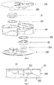
- another embodiment of the invention provides a tweeter, wherein the central axis of the first tweeter unit 21 does not coincide with the central axis of the second tweeter unit 22.
- the horns 241 of the left sound track are not symmetrical in position with the horns 242 of the right sound track, namely, the horizontal projection of the first tweeter unit 21 does not overlap that of the second tweeter unit 22, and the central axis of the first tweeter unit 21, the central axis of the second tweeter unit 22, and the central axis of the radiation structure 23 do not coincide with one another.
- Fig. 7 is a section view of the assembly after the components in Fig. 6 have been assembled.
- the radiation structure 23 constituted by a plurality of horns is formed by detached components, comprising an upper structure 231, a lower structure 232 and an intermediate structure 230.
- the first tweeter unit 21 and the second tweeter unit 22 are assembled on the radiation structure 23 via a first sealing foam 251 and a second sealing foam 252, respectively, a third sealing foam 253 seals the gaps generated by directly assembling the upper structure 231 and the intermediate structure 230 of the radiation structure 23, and a fourth sealing foam 254 seals the gaps generated by directly assembling the lower structure 232 and the intermediate structure 230 of the radiation structure 23, to ensure that all of the sound waves of the left sound track of the first tweeter unit 21 enter the horns 241 of the left sound track along the first sound track openings 271, and all of the sound waves of the right sound track of the second tweeter unit 22 enter the horns 242 of the right sound track along the second sound track openings 272.
- Fig. 9 it shows a perspective view of the assembly after the components in Fig. 6 have been assembled.
- Fig. 8 it shows a plan view of the radiation structure with the components in Fig. 6 assembled and the upper structure removed. The horizontal projection of the first tweeter unit 21 and that of the second tweeter unit 22 stagger.
- the first tweeter unit 21 partially overlaps the second tweeter unit 22 in the axial direction. Namely, in the direction vertical to the axial direction, the first tweeter unit 21 and the second tweeter unit 22 have an overlapping portion.
- the total thickness of the radiation structure 23 is less than the sum of the thickness of the first tweeter unit 21 and the thickness of the second tweeter unit 22, thereby ensuring that omnidirectional sound field can be realized with an audio equipment of smaller volume.
- the number of the horns of the left sound track is the same as the number of the horns of the right sound track, the horns 241 of the left sound track and the horns 242 of the right sound track are disposed at intervals, and the thicknesses of the partition walls between the horns can be adjusted according to actual needs.
- the horns 241 of the left sound track and the horns 242 of the right sound track are staggered in horizontal direction, the horns 241 of the left sound track are turned 180°in horizontal direction and then 180°in vertical direction, and finally are consistent in position with the horns 242 of the right sound track.
- the central axis of the first tweeter unit does not coincide with the central axis of the second tweeter unit.
- Fig. 10 is a flow chart of a method for realizing omnidirectional high pitch sound field provided by an embodiment of the present invention, the method comprising:
- it further provides a first sealing foam matching the first tweeter unit, and provides a second sealing foam matching the second tweeter unit, wherein the first sealing foam can surround the first tweeter unit without contacting the diaphragm of the first tweeter unit, and the second sealing foam can surround the second tweeter unit without contacting the diaphragm of the second tweeter unit.
- phase cones In another preferred embodiment, it further provides a first phase cone and a second phase cone, wherein the first phase cone is fixed by a support frame symmetrically disposed on the horns of the left sound track and located in front of the diaphragm of the first tweeter unit; and the second phase cone is fixed by a support frame symmetrically disposed on the horns of the right sound track and located in front of the diaphragm of the second tweeter unit.
- the structure of phase cones helps sound spread more evenly to the horns of both left and right sound tracks. Symmetrical disposition of support frames on the corresponding horns for each of the phase corns helps the sound spread more evenly.
- the plurality of horns evenly on a whole plane, wherein the number of the horns of the left sound track is two or more, and correspondingly, the number of the horns of the right sound track is also two or more.
- the number of the horns of the left and right sound tracks in this embodiment are six or eight, respectively.
- the central axis of the first tweeter unit may coincide with the central axis of the second tweeter unit, or, the central axis of the first tweeter unit may not coincide with the central axis of the second tweeter unit.
- the central axis of the first tweeter unit coincides with the central axis of the second tweeter unit, it is preferably disposed that the horns of the left sound track and the horns of the right sound track are symmetrical in position.
- the central axis of the first tweeter unit does not coincide with the central axis of the second tweeter unit, it may be disposed that the horns of the left sound track and the horns of the right sound track are not symmetrical in position; preferably, the horns of the left sound track are turned 180° in horizontal direction and then 180° in vertical direction, and finally are consistent in position with the horns of the right sound track.
- the central axis of the first tweeter unit does not coincide with the central axis of the second tweeter unit, it may also be disposed that the first tweeter unit partially overlaps the second tweeter unit in the axial direction.
- the total thickness of the radiation structure is less than the sum of the thickness of the first tweeter unit and the thickness of the second tweeter unit, thereby ensuring that omnidirectional sound field can be realized with an audio equipment of smaller volume.
- the embodiments of the present invention provide a tweeter and a method for realizing omnidirectional high pitch sound field.
- the tweeter comprises a first tweeter unit corresponding to the left sound track, a second tweeter unit corresponding to the right sound track, a radiation structure formed by a plurality of horns, and it has advantages of simple structure, small volume and low cost.
- the tweeter has stereo effect.
- the sound wave emitted by the horns can cover horizontal 360°. Therefore, it effectively solves the problem that the acoustic structure in the prior art cannot realize 360° surround stereo under the general request of miniaturization and low cost.
Landscapes
- Engineering & Computer Science (AREA)
- Physics & Mathematics (AREA)
- Acoustics & Sound (AREA)
- Signal Processing (AREA)
- Health & Medical Sciences (AREA)
- Otolaryngology (AREA)
- Manufacturing & Machinery (AREA)
- Audible-Bandwidth Dynamoelectric Transducers Other Than Pickups (AREA)
- Obtaining Desirable Characteristics In Audible-Bandwidth Transducers (AREA)
Applications Claiming Priority (2)
| Application Number | Priority Date | Filing Date | Title |
|---|---|---|---|
| CN201410598848.9A CN104378717B (zh) | 2014-10-30 | 2014-10-30 | 一种高音扬声器及一种实现全指向高音声场的方法 |
| PCT/CN2015/085582 WO2016065962A1 (zh) | 2014-10-30 | 2015-07-30 | 一种高音扬声器及一种实现全指向高音声场的方法 |
Publications (3)
| Publication Number | Publication Date |
|---|---|
| EP3046337A1 true EP3046337A1 (de) | 2016-07-20 |
| EP3046337A4 EP3046337A4 (de) | 2017-02-22 |
| EP3046337B1 EP3046337B1 (de) | 2018-09-12 |
Family
ID=52557316
Family Applications (1)
| Application Number | Title | Priority Date | Filing Date |
|---|---|---|---|
| EP15810779.7A Not-in-force EP3046337B1 (de) | 2014-10-30 | 2015-07-30 | Hochtonlautsprecher und verfahren zur erzielung eines omnidirektionalen hochtonschallfeldes |
Country Status (5)
| Country | Link |
|---|---|
| US (1) | US9906861B2 (de) |
| EP (1) | EP3046337B1 (de) |
| CN (1) | CN104378717B (de) |
| DK (1) | DK3046337T3 (de) |
| WO (1) | WO2016065962A1 (de) |
Families Citing this family (9)
| Publication number | Priority date | Publication date | Assignee | Title |
|---|---|---|---|---|
| CN104378717B (zh) * | 2014-10-30 | 2016-09-28 | 歌尔股份有限公司 | 一种高音扬声器及一种实现全指向高音声场的方法 |
| CN106068005B (zh) * | 2015-10-13 | 2021-11-05 | 北京小鸟听听科技有限公司 | 一种扬声器及扬声器系统 |
| CN108291440B (zh) | 2015-11-11 | 2022-03-29 | 斯伦贝谢技术有限公司 | 估算核磁共振测量质量 |
| CN107708043B (zh) * | 2017-11-14 | 2024-05-24 | 深圳东原电子有限公司 | 一种具有水平全指向号角阵列的压缩式高音扬声器总成及工作原理 |
| CN108012207A (zh) * | 2017-11-30 | 2018-05-08 | 泰兴扬声电子有限公司 | 一种高指向性双辐射高清晰号角喇叭 |
| WO2019136740A1 (zh) * | 2018-01-15 | 2019-07-18 | 深圳东原电子有限公司 | 一种具有水平全指向号角阵列的压缩式高音扬声器总成及工作原理 |
| WO2021071488A1 (en) * | 2019-10-10 | 2021-04-15 | Harman International Industries, Incorporated | Omnidirectional loudspeaker and compression driver therefor |
| US11445303B2 (en) | 2020-10-16 | 2022-09-13 | Harman International Industries, Incorporated | Omnidirectional loudspeaker and compression driver therefor |
| US12363474B2 (en) | 2020-11-26 | 2025-07-15 | Harman International Industries, Incorporated | Omnidirectional loudspeaker with asymmetric vertical directivity |
Family Cites Families (19)
| Publication number | Priority date | Publication date | Assignee | Title |
|---|---|---|---|---|
| SE387511B (sv) * | 1973-08-24 | 1976-09-06 | S Carlsson | Hogtalare for anvendning vid sterofonisk ljudatergivning, samt av tva sadana hogtalare bestaende hogtalarpar |
| JPS51163901U (de) * | 1975-06-19 | 1976-12-27 | ||
| US4496021A (en) * | 1983-02-18 | 1985-01-29 | Emmanuel Berlant | 360 Degree radial reflex orthospectral horn for high-frequency loudspeakers |
| FI81471C (fi) * | 1988-11-08 | 1990-10-10 | Timo Tarkkonen | Hoegtalare givande ett tredimensionellt stereoljudintryck. |
| US5870484A (en) * | 1995-09-05 | 1999-02-09 | Greenberger; Hal | Loudspeaker array with signal dependent radiation pattern |
| JPH10313495A (ja) * | 1997-05-12 | 1998-11-24 | Sony Corp | 音響装置 |
| CN2426256Y (zh) * | 2000-06-07 | 2001-04-04 | 常龙祥 | 旋转式音箱 |
| JP2003037897A (ja) * | 2001-07-23 | 2003-02-07 | Mechanical Research:Kk | スピーカシステム |
| JP4273048B2 (ja) * | 2004-05-31 | 2009-06-03 | ティーオーエー株式会社 | スピーカシステム及びスピーカクラスターシステム |
| CN201163815Y (zh) * | 2008-03-11 | 2008-12-10 | 刘恩海 | 新型高音扬声器 |
| DE102008058028A1 (de) * | 2008-11-18 | 2010-05-20 | K+H Vertriebs- Und Entwicklungsgesellschaft Mbh | Lautsprechereinheit |
| CN201435812Y (zh) * | 2009-06-12 | 2010-03-31 | 陈权江 | 一种全方位螺旋状声道扬声器 |
| CN201550266U (zh) * | 2009-09-29 | 2010-08-11 | 先歌国际影音股份有限公司 | 多方向发声系统 |
| WO2012174698A1 (en) * | 2011-06-20 | 2012-12-27 | Nokia Corporation | An apparatus |
| CN102438190A (zh) * | 2011-12-14 | 2012-05-02 | 南京琅声声学科技有限公司 | 一种辐射角灵活可调的扬声器组及设置方法 |
| CN202652517U (zh) * | 2012-04-11 | 2013-01-02 | 天津洪波电子集团有限公司 | 双向号筒扬声器 |
| CN203279147U (zh) * | 2013-06-06 | 2013-11-06 | 无锡杰夫电声有限公司 | 号角式多点激励扬声器箱 |
| CN204206437U (zh) * | 2014-10-30 | 2015-03-11 | 歌尔声学股份有限公司 | 一种高音扬声器 |
| CN104378717B (zh) * | 2014-10-30 | 2016-09-28 | 歌尔股份有限公司 | 一种高音扬声器及一种实现全指向高音声场的方法 |
-
2014
- 2014-10-30 CN CN201410598848.9A patent/CN104378717B/zh active Active
-
2015
- 2015-07-30 US US14/901,611 patent/US9906861B2/en not_active Expired - Fee Related
- 2015-07-30 DK DK15810779.7T patent/DK3046337T3/en active
- 2015-07-30 EP EP15810779.7A patent/EP3046337B1/de not_active Not-in-force
- 2015-07-30 WO PCT/CN2015/085582 patent/WO2016065962A1/zh not_active Ceased
Also Published As
| Publication number | Publication date |
|---|---|
| CN104378717A (zh) | 2015-02-25 |
| EP3046337A4 (de) | 2017-02-22 |
| EP3046337B1 (de) | 2018-09-12 |
| WO2016065962A1 (zh) | 2016-05-06 |
| US20160309257A1 (en) | 2016-10-20 |
| CN104378717B (zh) | 2016-09-28 |
| DK3046337T3 (en) | 2018-12-03 |
| US9906861B2 (en) | 2018-02-27 |
Similar Documents
| Publication | Publication Date | Title |
|---|---|---|
| US9906861B2 (en) | Tweeter and method for realizing omnidirectional high pitch sound field | |
| US9998809B2 (en) | Loudspeaker module | |
| US9807512B2 (en) | Speaker | |
| US10667036B2 (en) | Lattice type speaker and lattice array speaker system having same | |
| US20180376240A1 (en) | Electro-acoustical transducer arrangements of a sound system | |
| JP2013542463A (ja) | モジュール式ホーンおよびホーンアレイ | |
| JP2013542463A6 (ja) | モジュール式ホーンおよびホーンアレイ | |
| CN102802100A (zh) | 扬声器模组 | |
| US11856362B2 (en) | Loudspeaker apparatus, loudspeaker, and structure | |
| US20160157010A1 (en) | Variable device for directing sound wavefronts | |
| EP4324220B1 (de) | Wellenleiter-lautsprecher mit schmaler apertur zur verwendung mit flachbildschirmvorrichtungen | |
| CN1795696A (zh) | 带有无源辐射器的室外扬声器 | |
| JP7581220B2 (ja) | ハイトチャンネルスピーカ用音響反射器 | |
| EP3420738B1 (de) | Planarlautsprecherverteiler für verbesserte schalldispersion | |
| KR101000015B1 (ko) | 스피커 구조 | |
| US9326084B2 (en) | Multi lobe stereo loudspeaker in one cabinet | |
| KR101044222B1 (ko) | 스피커 시스템 | |
| US10051362B2 (en) | Loudspeaker device | |
| CN108605182A (zh) | 用于扬声器中衍射槽的适形适配器 | |
| CN106068005B (zh) | 一种扬声器及扬声器系统 | |
| CN107980224B (zh) | 全向扬声器系统及相关设备和方法 | |
| KR101538901B1 (ko) | 스피커 시스템 | |
| FI116506B (fi) | Ympärisäteilevä stereokaiutin | |
| CN204206437U (zh) | 一种高音扬声器 | |
| CN111800707B (zh) | 一种多无源辐射器音箱 |
Legal Events
| Date | Code | Title | Description |
|---|---|---|---|
| PUAI | Public reference made under article 153(3) epc to a published international application that has entered the european phase |
Free format text: ORIGINAL CODE: 0009012 |
|
| 17P | Request for examination filed |
Effective date: 20151230 |
|
| AK | Designated contracting states |
Kind code of ref document: A1 Designated state(s): AL AT BE BG CH CY CZ DE DK EE ES FI FR GB GR HR HU IE IS IT LI LT LU LV MC MK MT NL NO PL PT RO RS SE SI SK SM TR |
|
| AX | Request for extension of the european patent |
Extension state: BA ME |
|
| A4 | Supplementary search report drawn up and despatched |
Effective date: 20170124 |
|
| RIC1 | Information provided on ipc code assigned before grant |
Ipc: H04R 1/34 20060101ALI20170118BHEP Ipc: H04R 1/40 20060101ALI20170118BHEP Ipc: H04R 1/32 20060101ALI20170118BHEP Ipc: H04R 5/02 20060101AFI20170118BHEP |
|
| STAA | Information on the status of an ep patent application or granted ep patent |
Free format text: STATUS: EXAMINATION IS IN PROGRESS |
|
| 17Q | First examination report despatched |
Effective date: 20170307 |
|
| DAV | Request for validation of the european patent (deleted) | ||
| DAX | Request for extension of the european patent (deleted) | ||
| GRAP | Despatch of communication of intention to grant a patent |
Free format text: ORIGINAL CODE: EPIDOSNIGR1 |
|
| STAA | Information on the status of an ep patent application or granted ep patent |
Free format text: STATUS: GRANT OF PATENT IS INTENDED |
|
| INTG | Intention to grant announced |
Effective date: 20180516 |
|
| GRAS | Grant fee paid |
Free format text: ORIGINAL CODE: EPIDOSNIGR3 |
|
| GRAA | (expected) grant |
Free format text: ORIGINAL CODE: 0009210 |
|
| STAA | Information on the status of an ep patent application or granted ep patent |
Free format text: STATUS: THE PATENT HAS BEEN GRANTED |
|
| AK | Designated contracting states |
Kind code of ref document: B1 Designated state(s): AL AT BE BG CH CY CZ DE DK EE ES FI FR GB GR HR HU IE IS IT LI LT LU LV MC MK MT NL NO PL PT RO RS SE SI SK SM TR |
|
| REG | Reference to a national code |
Ref country code: GB Ref legal event code: FG4D |
|
| REG | Reference to a national code |
Ref country code: CH Ref legal event code: EP |
|
| REG | Reference to a national code |
Ref country code: IE Ref legal event code: FG4D |
|
| REG | Reference to a national code |
Ref country code: DE Ref legal event code: R096 Ref document number: 602015016327 Country of ref document: DE |
|
| REG | Reference to a national code |
Ref country code: AT Ref legal event code: REF Ref document number: 1042032 Country of ref document: AT Kind code of ref document: T Effective date: 20181015 |
|
| REG | Reference to a national code |
Ref country code: DK Ref legal event code: T3 Effective date: 20181126 |
|
| REG | Reference to a national code |
Ref country code: NL Ref legal event code: MP Effective date: 20180912 |
|
| REG | Reference to a national code |
Ref country code: LT Ref legal event code: MG4D |
|
| PG25 | Lapsed in a contracting state [announced via postgrant information from national office to epo] |
Ref country code: GR Free format text: LAPSE BECAUSE OF FAILURE TO SUBMIT A TRANSLATION OF THE DESCRIPTION OR TO PAY THE FEE WITHIN THE PRESCRIBED TIME-LIMIT Effective date: 20181213 Ref country code: SE Free format text: LAPSE BECAUSE OF FAILURE TO SUBMIT A TRANSLATION OF THE DESCRIPTION OR TO PAY THE FEE WITHIN THE PRESCRIBED TIME-LIMIT Effective date: 20180912 Ref country code: NO Free format text: LAPSE BECAUSE OF FAILURE TO SUBMIT A TRANSLATION OF THE DESCRIPTION OR TO PAY THE FEE WITHIN THE PRESCRIBED TIME-LIMIT Effective date: 20181212 Ref country code: BG Free format text: LAPSE BECAUSE OF FAILURE TO SUBMIT A TRANSLATION OF THE DESCRIPTION OR TO PAY THE FEE WITHIN THE PRESCRIBED TIME-LIMIT Effective date: 20181212 Ref country code: RS Free format text: LAPSE BECAUSE OF FAILURE TO SUBMIT A TRANSLATION OF THE DESCRIPTION OR TO PAY THE FEE WITHIN THE PRESCRIBED TIME-LIMIT Effective date: 20180912 Ref country code: LT Free format text: LAPSE BECAUSE OF FAILURE TO SUBMIT A TRANSLATION OF THE DESCRIPTION OR TO PAY THE FEE WITHIN THE PRESCRIBED TIME-LIMIT Effective date: 20180912 Ref country code: FI Free format text: LAPSE BECAUSE OF FAILURE TO SUBMIT A TRANSLATION OF THE DESCRIPTION OR TO PAY THE FEE WITHIN THE PRESCRIBED TIME-LIMIT Effective date: 20180912 |
|
| PG25 | Lapsed in a contracting state [announced via postgrant information from national office to epo] |
Ref country code: AL Free format text: LAPSE BECAUSE OF FAILURE TO SUBMIT A TRANSLATION OF THE DESCRIPTION OR TO PAY THE FEE WITHIN THE PRESCRIBED TIME-LIMIT Effective date: 20180912 Ref country code: LV Free format text: LAPSE BECAUSE OF FAILURE TO SUBMIT A TRANSLATION OF THE DESCRIPTION OR TO PAY THE FEE WITHIN THE PRESCRIBED TIME-LIMIT Effective date: 20180912 Ref country code: HR Free format text: LAPSE BECAUSE OF FAILURE TO SUBMIT A TRANSLATION OF THE DESCRIPTION OR TO PAY THE FEE WITHIN THE PRESCRIBED TIME-LIMIT Effective date: 20180912 |
|
| REG | Reference to a national code |
Ref country code: AT Ref legal event code: MK05 Ref document number: 1042032 Country of ref document: AT Kind code of ref document: T Effective date: 20180912 |
|
| PG25 | Lapsed in a contracting state [announced via postgrant information from national office to epo] |
Ref country code: EE Free format text: LAPSE BECAUSE OF FAILURE TO SUBMIT A TRANSLATION OF THE DESCRIPTION OR TO PAY THE FEE WITHIN THE PRESCRIBED TIME-LIMIT Effective date: 20180912 Ref country code: PL Free format text: LAPSE BECAUSE OF FAILURE TO SUBMIT A TRANSLATION OF THE DESCRIPTION OR TO PAY THE FEE WITHIN THE PRESCRIBED TIME-LIMIT Effective date: 20180912 Ref country code: IT Free format text: LAPSE BECAUSE OF FAILURE TO SUBMIT A TRANSLATION OF THE DESCRIPTION OR TO PAY THE FEE WITHIN THE PRESCRIBED TIME-LIMIT Effective date: 20180912 Ref country code: CZ Free format text: LAPSE BECAUSE OF FAILURE TO SUBMIT A TRANSLATION OF THE DESCRIPTION OR TO PAY THE FEE WITHIN THE PRESCRIBED TIME-LIMIT Effective date: 20180912 Ref country code: NL Free format text: LAPSE BECAUSE OF FAILURE TO SUBMIT A TRANSLATION OF THE DESCRIPTION OR TO PAY THE FEE WITHIN THE PRESCRIBED TIME-LIMIT Effective date: 20180912 Ref country code: AT Free format text: LAPSE BECAUSE OF FAILURE TO SUBMIT A TRANSLATION OF THE DESCRIPTION OR TO PAY THE FEE WITHIN THE PRESCRIBED TIME-LIMIT Effective date: 20180912 Ref country code: RO Free format text: LAPSE BECAUSE OF FAILURE TO SUBMIT A TRANSLATION OF THE DESCRIPTION OR TO PAY THE FEE WITHIN THE PRESCRIBED TIME-LIMIT Effective date: 20180912 Ref country code: IS Free format text: LAPSE BECAUSE OF FAILURE TO SUBMIT A TRANSLATION OF THE DESCRIPTION OR TO PAY THE FEE WITHIN THE PRESCRIBED TIME-LIMIT Effective date: 20190112 |
|
| PG25 | Lapsed in a contracting state [announced via postgrant information from national office to epo] |
Ref country code: PT Free format text: LAPSE BECAUSE OF FAILURE TO SUBMIT A TRANSLATION OF THE DESCRIPTION OR TO PAY THE FEE WITHIN THE PRESCRIBED TIME-LIMIT Effective date: 20190112 Ref country code: SK Free format text: LAPSE BECAUSE OF FAILURE TO SUBMIT A TRANSLATION OF THE DESCRIPTION OR TO PAY THE FEE WITHIN THE PRESCRIBED TIME-LIMIT Effective date: 20180912 Ref country code: SM Free format text: LAPSE BECAUSE OF FAILURE TO SUBMIT A TRANSLATION OF THE DESCRIPTION OR TO PAY THE FEE WITHIN THE PRESCRIBED TIME-LIMIT Effective date: 20180912 |
|
| REG | Reference to a national code |
Ref country code: DE Ref legal event code: R097 Ref document number: 602015016327 Country of ref document: DE |
|
| PLBE | No opposition filed within time limit |
Free format text: ORIGINAL CODE: 0009261 |
|
| STAA | Information on the status of an ep patent application or granted ep patent |
Free format text: STATUS: NO OPPOSITION FILED WITHIN TIME LIMIT |
|
| PG25 | Lapsed in a contracting state [announced via postgrant information from national office to epo] |
Ref country code: ES Free format text: LAPSE BECAUSE OF FAILURE TO SUBMIT A TRANSLATION OF THE DESCRIPTION OR TO PAY THE FEE WITHIN THE PRESCRIBED TIME-LIMIT Effective date: 20180912 |
|
| 26N | No opposition filed |
Effective date: 20190613 |
|
| PG25 | Lapsed in a contracting state [announced via postgrant information from national office to epo] |
Ref country code: SI Free format text: LAPSE BECAUSE OF FAILURE TO SUBMIT A TRANSLATION OF THE DESCRIPTION OR TO PAY THE FEE WITHIN THE PRESCRIBED TIME-LIMIT Effective date: 20180912 |
|
| PG25 | Lapsed in a contracting state [announced via postgrant information from national office to epo] |
Ref country code: MC Free format text: LAPSE BECAUSE OF FAILURE TO SUBMIT A TRANSLATION OF THE DESCRIPTION OR TO PAY THE FEE WITHIN THE PRESCRIBED TIME-LIMIT Effective date: 20180912 |
|
| REG | Reference to a national code |
Ref country code: CH Ref legal event code: PL |
|
| PG25 | Lapsed in a contracting state [announced via postgrant information from national office to epo] |
Ref country code: TR Free format text: LAPSE BECAUSE OF FAILURE TO SUBMIT A TRANSLATION OF THE DESCRIPTION OR TO PAY THE FEE WITHIN THE PRESCRIBED TIME-LIMIT Effective date: 20180912 |
|
| REG | Reference to a national code |
Ref country code: BE Ref legal event code: MM Effective date: 20190731 |
|
| PG25 | Lapsed in a contracting state [announced via postgrant information from national office to epo] |
Ref country code: LI Free format text: LAPSE BECAUSE OF NON-PAYMENT OF DUE FEES Effective date: 20190731 Ref country code: LU Free format text: LAPSE BECAUSE OF NON-PAYMENT OF DUE FEES Effective date: 20190730 Ref country code: CH Free format text: LAPSE BECAUSE OF NON-PAYMENT OF DUE FEES Effective date: 20190731 Ref country code: BE Free format text: LAPSE BECAUSE OF NON-PAYMENT OF DUE FEES Effective date: 20190731 |
|
| PG25 | Lapsed in a contracting state [announced via postgrant information from national office to epo] |
Ref country code: IE Free format text: LAPSE BECAUSE OF NON-PAYMENT OF DUE FEES Effective date: 20190730 |
|
| PG25 | Lapsed in a contracting state [announced via postgrant information from national office to epo] |
Ref country code: CY Free format text: LAPSE BECAUSE OF FAILURE TO SUBMIT A TRANSLATION OF THE DESCRIPTION OR TO PAY THE FEE WITHIN THE PRESCRIBED TIME-LIMIT Effective date: 20180912 |
|
| PG25 | Lapsed in a contracting state [announced via postgrant information from national office to epo] |
Ref country code: MT Free format text: LAPSE BECAUSE OF FAILURE TO SUBMIT A TRANSLATION OF THE DESCRIPTION OR TO PAY THE FEE WITHIN THE PRESCRIBED TIME-LIMIT Effective date: 20180912 Ref country code: HU Free format text: LAPSE BECAUSE OF FAILURE TO SUBMIT A TRANSLATION OF THE DESCRIPTION OR TO PAY THE FEE WITHIN THE PRESCRIBED TIME-LIMIT; INVALID AB INITIO Effective date: 20150730 |
|
| PG25 | Lapsed in a contracting state [announced via postgrant information from national office to epo] |
Ref country code: MK Free format text: LAPSE BECAUSE OF FAILURE TO SUBMIT A TRANSLATION OF THE DESCRIPTION OR TO PAY THE FEE WITHIN THE PRESCRIBED TIME-LIMIT Effective date: 20180912 |
|
| PGFP | Annual fee paid to national office [announced via postgrant information from national office to epo] |
Ref country code: DK Payment date: 20240628 Year of fee payment: 10 |
|
| PGFP | Annual fee paid to national office [announced via postgrant information from national office to epo] |
Ref country code: FR Payment date: 20240619 Year of fee payment: 10 |
|
| PGFP | Annual fee paid to national office [announced via postgrant information from national office to epo] |
Ref country code: DE Payment date: 20240712 Year of fee payment: 10 |
|
| PGFP | Annual fee paid to national office [announced via postgrant information from national office to epo] |
Ref country code: GB Payment date: 20240729 Year of fee payment: 10 |
|
| REG | Reference to a national code |
Ref country code: DE Ref legal event code: R119 Ref document number: 602015016327 Country of ref document: DE |
|
| REG | Reference to a national code |
Ref country code: DK Ref legal event code: EBP Effective date: 20250731 |
|
| GBPC | Gb: european patent ceased through non-payment of renewal fee |
Effective date: 20250730 |
|
| PG25 | Lapsed in a contracting state [announced via postgrant information from national office to epo] |
Ref country code: GB Free format text: LAPSE BECAUSE OF NON-PAYMENT OF DUE FEES Effective date: 20250730 |
|
| PG25 | Lapsed in a contracting state [announced via postgrant information from national office to epo] |
Ref country code: DE Free format text: LAPSE BECAUSE OF NON-PAYMENT OF DUE FEES Effective date: 20260203 |
|
| PG25 | Lapsed in a contracting state [announced via postgrant information from national office to epo] |
Ref country code: FR Free format text: LAPSE BECAUSE OF NON-PAYMENT OF DUE FEES Effective date: 20250731 |