EP3046657B1 - Procédé et système de biofiltre pour l'élimination de h2s d'un courant gazeux de production d'énergie contaminé par h2s contenant du méthane et utilisation d'un tel système de biofiltre - Google Patents
Procédé et système de biofiltre pour l'élimination de h2s d'un courant gazeux de production d'énergie contaminé par h2s contenant du méthane et utilisation d'un tel système de biofiltre Download PDFInfo
- Publication number
- EP3046657B1 EP3046657B1 EP14771844.9A EP14771844A EP3046657B1 EP 3046657 B1 EP3046657 B1 EP 3046657B1 EP 14771844 A EP14771844 A EP 14771844A EP 3046657 B1 EP3046657 B1 EP 3046657B1
- Authority
- EP
- European Patent Office
- Prior art keywords
- gas stream
- energy production
- biofilter
- production gas
- microorganisms
- Prior art date
- Legal status (The legal status is an assumption and is not a legal conclusion. Google has not performed a legal analysis and makes no representation as to the accuracy of the status listed.)
- Active
Links
Images
Classifications
-
- C—CHEMISTRY; METALLURGY
- C10—PETROLEUM, GAS OR COKE INDUSTRIES; TECHNICAL GASES CONTAINING CARBON MONOXIDE; FUELS; LUBRICANTS; PEAT
- C10L—FUELS NOT OTHERWISE PROVIDED FOR; NATURAL GAS; SYNTHETIC NATURAL GAS OBTAINED BY PROCESSES NOT COVERED BY SUBCLASSES C10G OR C10K; LIQUIFIED PETROLEUM GAS; USE OF ADDITIVES TO FUELS OR FIRES; FIRE-LIGHTERS
- C10L3/00—Gaseous fuels; Natural gas; Synthetic natural gas obtained by processes not covered by subclass C10G, C10K; Liquefied petroleum gas
- C10L3/06—Natural gas; Synthetic natural gas obtained by processes not covered by C10G, C10K3/02 or C10K3/04
- C10L3/10—Working-up natural gas or synthetic natural gas
- C10L3/101—Removal of contaminants
- C10L3/102—Removal of contaminants of acid contaminants
- C10L3/103—Sulfur containing contaminants
-
- C—CHEMISTRY; METALLURGY
- C10—PETROLEUM, GAS OR COKE INDUSTRIES; TECHNICAL GASES CONTAINING CARBON MONOXIDE; FUELS; LUBRICANTS; PEAT
- C10L—FUELS NOT OTHERWISE PROVIDED FOR; NATURAL GAS; SYNTHETIC NATURAL GAS OBTAINED BY PROCESSES NOT COVERED BY SUBCLASSES C10G OR C10K; LIQUIFIED PETROLEUM GAS; USE OF ADDITIVES TO FUELS OR FIRES; FIRE-LIGHTERS
- C10L2290/00—Fuel preparation or upgrading, processes or apparatus therefore, comprising specific process steps or apparatus units
- C10L2290/14—Injection, e.g. in a reactor or a fuel stream during fuel production
- C10L2290/141—Injection, e.g. in a reactor or a fuel stream during fuel production of additive or catalyst
-
- C—CHEMISTRY; METALLURGY
- C10—PETROLEUM, GAS OR COKE INDUSTRIES; TECHNICAL GASES CONTAINING CARBON MONOXIDE; FUELS; LUBRICANTS; PEAT
- C10L—FUELS NOT OTHERWISE PROVIDED FOR; NATURAL GAS; SYNTHETIC NATURAL GAS OBTAINED BY PROCESSES NOT COVERED BY SUBCLASSES C10G OR C10K; LIQUIFIED PETROLEUM GAS; USE OF ADDITIVES TO FUELS OR FIRES; FIRE-LIGHTERS
- C10L2290/00—Fuel preparation or upgrading, processes or apparatus therefore, comprising specific process steps or apparatus units
- C10L2290/26—Composting, fermenting or anaerobic digestion fuel components or materials from which fuels are prepared
-
- C—CHEMISTRY; METALLURGY
- C10—PETROLEUM, GAS OR COKE INDUSTRIES; TECHNICAL GASES CONTAINING CARBON MONOXIDE; FUELS; LUBRICANTS; PEAT
- C10L—FUELS NOT OTHERWISE PROVIDED FOR; NATURAL GAS; SYNTHETIC NATURAL GAS OBTAINED BY PROCESSES NOT COVERED BY SUBCLASSES C10G OR C10K; LIQUIFIED PETROLEUM GAS; USE OF ADDITIVES TO FUELS OR FIRES; FIRE-LIGHTERS
- C10L2290/00—Fuel preparation or upgrading, processes or apparatus therefore, comprising specific process steps or apparatus units
- C10L2290/54—Specific separation steps for separating fractions, components or impurities during preparation or upgrading of a fuel
- C10L2290/547—Filtration for separating fractions, components or impurities during preparation or upgrading of a fuel
Definitions
- the invention relates to a process for removing H 2 S (hydrogen sulphide) from a H 2 S contaminated energy production gas stream containing methane, using an aqueous biofilter system comprising a biofilter having biofilter support material constituting a biofilter bed supporting a biofilm having microorganisms that are capable of oxidizing H 2 S.
- the process therewith comprises the steps of contacting the H 2 S contaminated energy production gas stream with the microorganisms and oxidation of at least part of the H 2 S in the H 2 S contaminated energy production gas stream by the microorganisms, resulting in a H 2 S depleted energy production gas stream.
- H 2 S contaminated energy production gases containing methane are biogas, natural gas or shale gas, these examples however not being limitative.
- Biogas is a mixture of gases that is produced by the biological breakdown of organic matter in the absence of oxygen. Biogas is produced through the anaerobic digestion or fermentation of biodegradable material such as biosolids, manures, sewage, municipal waste, green waste, plant material and energy crops. Biogas is comprised primarily of methane and carbon dioxide.
- Natural gas is a naturally occurring hydrocarbon gas mixture consisting primarily of methane. It commonly furthermore includes varying amounts of other higher alkanes and lesser percentages of carbon dioxide, nitrogen and hydrogen sulphide.
- Shale gas is a natural gas that can be found trapped within shale formations. Shale gas is extracted from fine-grained sedimentary rocks known as shale that can be rich sources of petroleum and natural gas. This gas is trapped within shale formations which are extracted by technology-oriented processes.
- biofilter systems When biofilter systems are applied as air or other gas stream treatment systems, these biofilter systems use microorganisms to remove impurities or contaminants in the air or gas stream.
- an air or gas stream is urged to flow through a moist, biologically active, packed biofilter bed consisting of biofilter support material containing microorganisms that are immobilized on the biofilter support material and forming a biofilm on the biofilter support material.
- the process underlying the operation of the biofilter is a three-step process.
- a phase transfer occurs wherein impurities in the air / gas stream such as H 2 S are transferred from the gaseous phase to the liquid phase, i.e. to the aqueous solution used to humidify the biofilm.
- This first step is followed by a second, adsorption step wherein, once in the liquid phase, the impurities are absorbed to the biofilter support material of the biofilter bed.
- a biodegradation step the impurities are biodegraded by the microorganisms of the biofilm.
- the invention furthermore relates to an aqueous biofilter system arranged to remove H 2 S from a H 2 S contaminated energy production gas stream containing methane.
- the aqueous biofilter system therewith comprises a biofilter having biofilter support material constituting a biofilter bed supporting a biofilm having microorganisms capable of oxidizing H 2 S, the biofilm being arranged to be contacted with the energy production gas stream and the microorganisms being arranged to remove at least part of the H 2 S out of the energy production gas stream resulting in a H 2 S depleted energy production gas stream.
- the invention also relates to the use of an aqueous biofilter system according to the invention for removing H 2 S from a H 2 S contaminated energy production gas stream containing methane.
- Bio gas treatment processes are based on microbial digestion of contaminants in the biological gas.
- Established systems for this purpose are bioscrubbers, biotrickling filters and biofilters.
- biofiltration uses naturally occurring microorganisms to biologically break down odors, solvents and other VOCs (volatile organic compounds) present in air streams such as waste air streams or gas streams such as energy production gas streams, into carbon dioxide and waste water. It is a completely natural process that does not use chemicals or produce waste.
- Biofiltration is a reliable and cost-effective way to eliminate odors, VOCs and H 2 S at manufacturing, municipal and processing facilities.
- the microorganisms which reside on the surface of the biofilter support media forming a biofilm use the pollutants as a food source. A cleaned air gas stream is then discharged to the environment.
- Biofiltration systems need to be run without strong variations in turnover of gas and contaminants as the microbial community reacts slowly on changes and has to be balanced.
- biofilter systems in removal of contaminants such as, amongst others, H 2 S from air and gas streams has already been known for a long time.
- a biofilter for treatment of waste waters and gases comprising a bed of coniferous tree barking residue containing microorganisms, is disclosed.
- a biofilter media including grains having a hydrophilic nucleus and a hydrophobic coating including microorganisms and a metallic agent that both assist in the breakdown of amongst others H 2 S.
- the biofilter media is housed in a biofilter system including elements for the irrigation and humidification of the air stream of the biofilter media by steam or spray to ensure that the biofilter media is operating at appropriate temperature and moisture levels to avoid build-up of biomass or chemical deposits.
- the nutrients required for microorganism viability are therewith present in the hydrophobic coating, this preferably as a blend of trace elements.
- the disadvantage of the system as disclosed in WO 2005/037403 for providing the nutrients required for microorganisms viability in the hydrophobic coating is that the nutrients are not renewed once the nutrients as present in the hydrophobic coating are exhausted.
- a system for removing H 2 S from methane uses aerobic microorganisms to remove the hydrogen sulphide from the gas stream and oxidize it back to sulphate, which will then combine with water to form sulphuric acid.
- the system includes providing at least one biofilter cartridge that functions to sustain microbial activity which will function to consume H 2 S contained in a stream of methane gas.
- EP0845288 describes a process for the removal of sulphides from a gas stream by scrubbing the gas with an aqueous washing liquid and treating the washing liquid with sulphide-oxidising bacteria in the presence of an electron acceptor and reusing the treated liquid as a washing liquid, wherein the scrubbing and the bacterial treatment are carried out in the same reactor and nitrate is used as the electron acceptor.
- the process is especially useful for desulphurising natural gas at high pressure.
- a process for removing hydrogen sulphide from a raw natural gas stream such as biogas from landfills or controlled anaerobic digestion is disclosed using oxygen, commonly in the form of air, to remove the H2S out of the raw natural gas stream.
- the natural gas stream is therewith passed through a separation unit to form on the one hand, a product stream comprising a high concentration of methane and on the other hand, a low pressure tail gas containing H 2 S which is passed through a biofilter including bacteria that degrades the H 2 S to sulphur and sulphate compounds that are washed from the biofilter.
- the process of claim 1 is provided for removing H 2 S from a H 2 S contaminated energy production gas stream containing methane, using an aqueous biofilter system, comprising a biofilm having biofilter support material constituting a biofilter bed and supporting a humidified biofilm having microorganisms that are capable of oxidizing H 2 S, wherein the process comprises the steps of
- anoxic means "nearly in absence of, or in the presence of a very low amount of oxygen", so that the oxidation reduction potential of the subsequent reaction ranges between 800 mV and -200 mV, preferably is about 400 mV.
- the abovementioned single step process using a biofilter system provides a simple and cost effective way to obtain a H 2 S depleted energy production gas stream. Furthermore, by oxidizing the H 2 S under anoxic conditions, the inflow of nitrogen in the biofilter system is limited, through which the quality of the energy production gas stream after treatment with the biofilter is maintained.
- the microorganisms In the biofilter support material, the microorganisms generate inert agents as well as other substances, i.e. mainly elemental sulphur, insoluble sulphate salts, formed by the microorganisms through the anoxic oxidation of the H 2 S such as calcium sulphate and/or organic sulphur compounds that precipitate in the biofilter support material.
- the nitrate solution comprises a chelating agent.
- this chelating agent preferably comprises ethylene diamine tetra acetic acid (EDTA).
- the nitrate solution that is used to enable the microorganisms to anoxically oxidize H 2 S preferably comprises a calcium nitrate solution.
- the process comprises the step of recirculating part of the H 2 S depleted energy gas stream to the biofilter and adding to the recirculated energy production gas stream a nutrient and/or nitrate solution prior to being contacted with the microorganisms of the biofilm.
- This recirculation is beneficial for the biofilter system since the H 2 S depleted energy gas stream, once passed through the biofilter support material, contains microorganisms, originating from the biofilm, and as a result of the recirculation, these microorganisms will also be reintroduced into the inlet of the biofilter system again. This increases the oxidation activity of the microorganisms in the entry area of the biofilter system, what would not be the case in the case of absence of recirculation.
- the process comprises the step of automatically adjusting the dosage of the nutrient solution, added to the H 2 S contaminated energy production gas stream, in relation to the H 2 S content in the H 2 S contaminated energy production gas stream at an inlet of the biofilter system.
- the biofilm is humidified by means of the energy production gas stream which has been pre-humidified prior to contacting the biofilm.
- the aqueous biofilter system of claim 6 is provided that is arranged to remove H 2 S from an H 2 S contaminated energy production gas stream containing methane, the aqueous biofilter system comprising a biofilter having biofilter support material constituting a biofilter bed and supporting a biofilm having microorganisms capable of oxidizing H 2 S, the biofilm being arranged to be contacted with the H 2 S contaminated energy production gas stream and the microorganisms being arranged to remove at least part of the H 2 S of the H 2 S contaminated energy production gas stream, resulting in an H 2 S depleted energy production gas stream, wherein the aqueous biofilter system comprises means for adding an aqueous nitrate solution to the H 2 S contaminated energy production gas stream prior to being contacted with the microorganisms of the biofilm, enabling the microorganisms to oxidize the H 2 S under anoxic conditions.
- Part of the H 2 S depleted energy production gas stream is recirculated, and an atomizer nozzle is used to atomize the nutrient and / or the nitrate solution.
- This recirculation will ensure that the atomization of the nutrient and / or the nitrate solution into the energy production gas stream produces a very fine droplet size.
- Pure hydraulic injectors can for instance not provide such fine aerosols.
- the nutrient and / or the nitrate solution are applied as fine droplets in the energy production gas stream, the nutrient and / or the nitrate solution will reach the microorganisms of the biofilm evenly. Also fouling and over-wetting of the biofilm is prevented in this way.
- solutions are not evenly sprayed over the biofilm since these solutions are only sprayed from a few points in the biofilter above the biofilter bed onto the biofilm.
- the biofilter system comprises a controller that is arranged to
- the controller can be arranged to adapt simultaneously the dosage of the nitrogen and the phosphor source in the nutrient solution.
- the controller can be arranged to adapt the dosage of the nitrogen and the phosphor source in the nutrient solution separately.
- the controller is preferably furthermore arranged to calculate a demand for recirculation of the part of the H 2 S depleted energy gas stream and to adjust the recirculation of the part of the H 2 S depleted energy gas stream in view of the demand of the nutrients solution.
- the controller is also preferably further arranged to dose the nutrients solution automatically in function of the H 2 S content in the H 2 S contaminated energy gas stream that is measured at the inlet according to a relation between the H 2 S -content in the energy gas stream, the nitrogen content and the phosphor content in the nutrient solution equalling to 20 : 10 : 1.
- an aqueous biofilter system according to the invention as described above for removing H 2 S from a H 2 S contaminated energy production gas stream containing methane is disclosed.
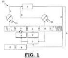
- Fig. 1 shows a scheme of the different parts of an exemplary embodiment of an aqueous biofilter system according to the invention.
- the process according to the invention for removing H 2 S from a H 2 S contaminated energy production gas stream containing methane uses an aqueous biofilter system comprising a biofilter having biofilter support material constituting a biofilter bed which supports a humidified biofilm.
- This humidified biofilm has microorganisms that are capable of anoxically oxidizing H 2 S.
- biofilter support material neither the type of microorganisms, nor the exact type of biofilter support material, nor the configuration of the biofilter bed used is critical to this invention, as long as the biofilter is capable of oxidizing the H 2 S in the energy production gas stream under anoxic conditions, resulting in a H 2 S depleted energy production gas stream.
- biofilter support material A variety of materials can be used as the biofilter support material including peat, compost material, soil, activated carbon, synthetic polymers, synthetic hydrogels and porous rocks.
- the biofilter support material may furthermore take a variety of forms such as cylindrical pellets, spheres, Raschig rings, irregular shapes, hollow tubes or fibers.
- the biofilter support material needs to be wetable with an aqueous solution and the surfaces of the support material are preferably porous.
- the support material must be such that microorganisms adhere thereto.
- Humidification of the biofilm is necessary because the moisture content of the biofilm plays an important role in the H 2 S removal efficiency. It is common to use water to humidify the biofilm.
- the process according to the invention comprises the steps of
- microorganisms e.g. bacteria
- Any type of microorganisms e.g. bacteria, can be used that are capable of oxidizing H 2 S present in the H 2 S contaminated energy production gas stream under anoxic conditions.
- Such standard and commonly used microorganisms in biofilter systems are known to the man skilled in the art and will not be listed and described in more detail here.
- the biofilter bed can take on every shape that is known to the skilled person, such as a flat bed, trickle bed, column bed, tubular bed, etc.
- the nitrate solution preferably comprises a calcium nitrate solution in order to allow the microorganisms to anoxically oxidize the H 2 S.
- the concentration of the nitrate solution is preferably 45 weight% to 50 weight%.
- the nitrate solution comprises a chelating agent.
- a chelating agent for instance, calcium sulphate (gypsum) precipitation, ethylene diamine tetra acetic acid (EDTA) is usable to solubilize calcium sulphate and other substances that might precipitate during the process.
- the nutrient solution for the microorganisms is added to the energy production gas stream, this prior to being contacted with the microorganisms in the biofilm, through which the nutrients become available to the microorganisms at the moment the energy production gas stream including the nutrient solution passes over the biofilm.
- part of the H 2 S depleted energy production gas stream is recirculated to the biofilter, together with the nutrient and/or nitrate solution that is added thereto.
- the nutrient and / or the nitrate solution, together with the recirculated part of the H 2 S depleted energy production gas stream, are injected to the biofilter using an atomizer nozzle.
- the nutritional dosage ratio of the nutrient solution is preferably automatically adjusted by measuring the content of the H 2 S in the H 2 S contaminated energy production gas stream at the inlet of the biofilter using a controller.
- the controller calculates the nutritional demand for the microorganisms and adjusts the nutritional dosage ratio of a carbon (C) source, a nitrogen (N) source and a phosphor (P) source in the nutrient solution preferably according to the ratio 100 : 10 : 1.
- this ratio is preferably adjustable by means of the controller, resulting in a better performance of the biofilter system and a lower demand of chemicals.
- the controller can therewith be arranged to adapt the dosage of the nitrogen and the phosphor source in the nutrient solution simultaneously, but can also be arranged to adapt the dosage of the nitrogen and the phosphor source in the nutrient solution separately.
- FIG. 1 illustrates a non-limiting exemplary embodiment of an aqueous biofilter system (10) for removing H 2 S from a raw, H 2 S contaminated energy production gas stream containing methane according to the invention.
- the untreated, raw H 2 S contaminated energy production gas stream (1) is injected by means of an atomizer nozzle (not shown on the figure) through a junction (9) into a biofilter (6).
- This biofilter (6) comprises a biofilter bed consisting of biofilter support material supporting a biofilm with microorganisms that are arranged to anoxically oxidize the H 2 S present in the H 2 S contaminated energy production stream (1) (as described above).
- a H 2 S depleted (cleaned) energy production stream is obtained.
- This H 2 S depleted energy production gas stream is passed through a splitter (11). The major part of this H 2 S depleted energy production gas stream is carried off to be used as energy production gas.
- H 2 S depleted energy production gas stream is recirculated to the biofilter (6) to be injected by the atomizer nozzle at the junction (9) in the biofilter (6) together with a nutrient solution and / or a nitrate solution that is used to anoxically oxidize the H 2 S in the H 2 S contaminated energy production gas stream.
- the nutrient solution preferably is a N/P solution that is stored in a nutrient solution tank (12) and that is applied in a predetermined dose using a nutrient dosage pump (4).
- the recirculated H 2 S depleted energy production gas stream is brought from the splitter (11) to the injector (8) using a gas pump (7).
- the temperature, H 2 S content, the flow and the pressure of the inflowing H 2 S contaminated energy production gas stream is measured.
- the temperature and the H 2 S content in the outflowing H 2 S depleted energy production gas stream is measured. As indicated by the dashed arrows (B) on figure 1 , these measurements are sent to a controller (3).
- the controller (3) By monitoring the H 2 S content in the H 2 S contaminated energy production gas stream present in the operational state of the biofilter system at the inlet of the biofilter (6), the controller (3) is able to calculate the nutritional demand for the microorganisms of the biofilm, and adjust the nutritional dosage ratio of a carbon source, a nitrogen source and a phosphor source of the nutrient solution equalling to 100 : 10 : 1. By measuring the H 2 S content at the outlet of the biofilter (6), the nutritional dosage ratio can be further adjusted. As indicated in figure 1 with the dashed arrows (A), the controller (3) is thereto provided to control the gas pump (7) and the nutrient solution dosage pump (4).
- biofilter (6) Since the biofilter (6) will produce some surplus sludge, mostly consisting of sulphuric acid from the anoxic oxidation of H 2 S, this sludge is removed from the biofilter (6) as effluent (5).
- This biofilter system (10) achieves an efficiency of 99.5% in H 2 S removal from a H 2 S contaminated energy production gas stream.
Landscapes
- Chemical & Material Sciences (AREA)
- Oil, Petroleum & Natural Gas (AREA)
- Engineering & Computer Science (AREA)
- Chemical Kinetics & Catalysis (AREA)
- General Chemical & Material Sciences (AREA)
- Organic Chemistry (AREA)
- Separation Using Semi-Permeable Membranes (AREA)
- Micro-Organisms Or Cultivation Processes Thereof (AREA)
- Purification Treatments By Anaerobic Or Anaerobic And Aerobic Bacteria Or Animals (AREA)
- Gas Separation By Absorption (AREA)
Claims (10)
- Procédé pour éliminer le sulfure d'hydrogène (H2S) d'un courant gazeux de production d'énergie contaminé par le H2S contenant du méthane, à l'aide d'un système de biofiltre aqueux (10) comprenant un biofiltre (6) ayant un matériau de support de biofiltre constituant un lit de biofiltre supportant un biofilm humidifié ayant des micro-organismes qui sont capables d'oxyder le H2S, dans lequel le procédé comprend les étapes- de mise en contact du courant gazeux de production d'énergie contaminé par le H2S avec les micro-organismes du biofilm humidifié ; et- d'oxydation d'au moins une partie du H2S dans le courant gazeux de production d'énergie contaminé par le H2S par les micro-organismes, ce qui entraîne un courant gazeux de production d'énergie appauvri en H2S,CARACTÉRISÉ EN CE QUE le procédé comprend en outre l'étape consistant à humidifier le biofilm au moyen du courant gazeux de production d'énergie qui a été préhumidifié avant d'être mis en contact avec le biofilm, à ajouter une solution aqueuse de nitrate au courant gazeux de production d'énergie contaminé par le H2S au moyen d'une buse de pulvérisation conçue pour pulvériser le nutriment et/ou la solution de nitrate dans le courant gazeux de production d'énergie, avant d'être mis en contact avec les micro-organismes, permettant aux micro-organismes d'oxyder le H2S dans des conditions anoxiques, de telle sorte qu'une partie du courant gazeux de production d'énergie appauvri en H2S soit remise en circulation, dans lequel le nutriment et/ou la solution de nitrate sont injectés dans le biofiltre conjointement avec la partie remise en circulation du courant gazeux de production d'énergie appauvri en H2S à l'aide de la buse de pulvérisation.
- Procédé selon la revendication 1, CARACTÉRISÉ EN CE QUE la solution de nitrate comprend un agent chélatant qui est conçu pour empêcher le bouchage d'agents de précipitation inertes et d'autres substances formés par l'oxydation anoxique du H2S par les micro-organismes.
- Procédé selon la revendication 2, CARACTÉRISÉ EN CE QUE, pour empêcher le bouchage d'une précipitation de sulfate de calcium, l'agent chélatant comprend de l'acide éthylène diamine tétraacétique (EDTA).
- Procédé selon l'une quelconque des revendications 1 à 3, CARACTÉRISÉ EN CE QUE la solution de nitrate comprend une solution de nitrate de calcium pour permettre aux micro-organismes d'oxyder le H2S dans des conditions anoxiques.
- Procédé selon l'une quelconque des revendications 1 à 4, CARACTÉRISÉ EN CE QUE le procédé comprend l'étape consistant à ajuster automatiquement le dosage de la solution nutritive ajoutée au courant gazeux de production d'énergie contaminé par le H2S par rapport à la teneur en H2S dans le courant gazeux de production d'énergie contaminé par le H2S au niveau d'un orifice d'entrée du système de biofiltre (10).
- Système de biofiltre aqueux (10) conçu pour éliminer le H2S d'un courant gazeux de production d'énergie contenant du méthane, le système de biofiltre aqueux (10) comprenant un biofiltre (6) ayant un matériau de support de biofiltre constituant un lit de biofiltre et supportant un biofilm ayant des micro-organismes capables d'oxyder le H2S, le biofilm étant conçu pour être mis en contact avec le courant gazeux de production d'énergie contaminé par le H2S (1) et les micro-organismes étant conçus pour éliminer au moins une partie du H2S du courant gazeux de production d'énergie contaminé par le H2S (1), ce qui entraîne un courant gazeux de production d'énergie appauvri en H2S (2), CARACTÉRISÉ EN CE QUE le système de biofiltre aqueux (10) comprend des moyens (4, 8) pour ajouter une solution aqueuse de nitrate au courant gazeux de production d'énergie contaminé par le H2S (9) avant d'être mis en contact avec le biofilm, de telle sorte que le biofilm soit humidifié au moyen du courant gazeux de production d'énergie qui a été préhumidifié avant d'être mis en contact avec le biofilm, permettant aux micro-organismes d'oxyder le H2S dans des conditions anoxiques, et dans lequel les moyens (4, 8) pour ajouter une solution nutritive et/ou de nitrate aqueuse au courant gazeux de production d'énergie contaminé par le H2S (1) comprennent une buse de pulvérisation conçue pour pulvériser la solution nutritive et/ou de nitrate dans le courant gazeux de production d'énergie contaminé par le H2S, de telle sorte qu'une partie du courant gazeux de production d'énergie appauvri en H2S soit remise en circulation et injectée dans le biofiltre, conjointement avec le nutriment et/ou la solution de nitrate, à l'aide de la buse de pulvérisation.
- Système de biofiltre aqueux (10) selon la revendication 6, CARACTÉRISÉ EN CE QUE le système de biofiltre (10) comprend un dispositif de commande (3) qui est conçu :• pour mesurer la teneur en H2S dans le courant gazeux de production d'énergie contaminé par le H2S (1) présent dans l'état fonctionnel du système de biofiltre (10) au niveau de l'orifice d'entrée du biofiltre (6),• pour calculer la demande nutritionnelle des micro-organismes et• pour ajuster le rapport de dosage nutritionnel d'une source de carbone, d'une source d'azote et d'une source de phosphore de la solution nutritive qui est égal à 100:10:1.
- Système de biofiltre aqueux (10) selon l'une quelconque des revendications 6 à 7, CARACTÉRISÉ EN CE QUE le dispositif de commande (3) est conçu pour adapter en même temps le dosage de la source d'azote et de la source de phosphore dans la solution nutritive.
- Système de biofiltre aqueux (10) selon l'une quelconque des revendications 6 à 8, CARACTÉRISÉ EN CE QUE le dispositif de commande (3) est conçu pour adapter le dosage de la source d'azote et de la source de phosphore dans la solution nutritive de façon distincte.
- Utilisation du système de biofiltre aqueux (10) selon l'une quelconque des revendications 6 à 9, pour éliminer le H2S d'un courant gazeux de production d'énergie contaminé par le H2S contenant du méthane.
Priority Applications (5)
| Application Number | Priority Date | Filing Date | Title |
|---|---|---|---|
| SM20180066T SMT201800066T1 (it) | 2013-09-18 | 2014-09-18 | Processo e sistema di biofiltrazione per l’eliminazione dell’h2s da un flusso di gas per la produzione energetica contaminato da h2s contenente metano e uso di tale sistema di biofiltrazione |
| PL14771844T PL3046657T3 (pl) | 2013-09-18 | 2014-09-18 | Proces i układ biofiltra do usuwania H2S z zanieczyszczonego przez H2S strumienia gazu energetycznego zawierającego metan oraz zastosowanie takiego układu biofiltra |
| RS20180140A RS56861B1 (sr) | 2013-09-18 | 2014-09-18 | Postupak i sistem za biofiltraciju za uklanjanje h2s iz struje h2s-kontaminiranog gasa za proizvodnju energije koji sadrži metan i upotreba takvog biofiltracijskog sistema |
| HRP20180249TT HRP20180249T1 (hr) | 2013-09-18 | 2014-09-18 | Postupak i biofiltarski sustav za uklanjanje h2s iz struje plina za proizvodnju energije koja sadržava metan, onečišćene s h2s i uporaba takvog biofiltarskog sustava |
| SI201430601T SI3046657T1 (en) | 2013-09-18 | 2014-09-18 | Process and biofilter system for h2s removal from a h2s contaminated energy production gas stream containing methane and use of such a biofilter system |
Applications Claiming Priority (2)
| Application Number | Priority Date | Filing Date | Title |
|---|---|---|---|
| NO20131255A NO20131255A1 (no) | 2013-09-18 | 2013-09-18 | Prosess og biofiltersystem for fjerning av H2S fra en H2S-kontaminert energiproduksjonsgasstrøm inneholdende metan og anvendelse av et slikt biofiltersystem |
| PCT/EP2014/069866 WO2015040100A1 (fr) | 2013-09-18 | 2014-09-18 | Procédé et système de biofiltre pour l'élimination de h2s d'un courant gazeux de production d'énergie contaminé par h2s contenant du méthane et utilisation d'un tel système de biofiltre |
Publications (2)
| Publication Number | Publication Date |
|---|---|
| EP3046657A1 EP3046657A1 (fr) | 2016-07-27 |
| EP3046657B1 true EP3046657B1 (fr) | 2017-12-27 |
Family
ID=51589286
Family Applications (1)
| Application Number | Title | Priority Date | Filing Date |
|---|---|---|---|
| EP14771844.9A Active EP3046657B1 (fr) | 2013-09-18 | 2014-09-18 | Procédé et système de biofiltre pour l'élimination de h2s d'un courant gazeux de production d'énergie contaminé par h2s contenant du méthane et utilisation d'un tel système de biofiltre |
Country Status (14)
| Country | Link |
|---|---|
| US (1) | US9890343B2 (fr) |
| EP (1) | EP3046657B1 (fr) |
| CY (1) | CY1120091T1 (fr) |
| DK (1) | DK3046657T3 (fr) |
| ES (1) | ES2661663T3 (fr) |
| HR (1) | HRP20180249T1 (fr) |
| HU (1) | HUE038495T2 (fr) |
| NO (2) | NO20131255A1 (fr) |
| PL (1) | PL3046657T3 (fr) |
| PT (1) | PT3046657T (fr) |
| RS (1) | RS56861B1 (fr) |
| SI (1) | SI3046657T1 (fr) |
| SM (1) | SMT201800066T1 (fr) |
| WO (1) | WO2015040100A1 (fr) |
Families Citing this family (1)
| Publication number | Priority date | Publication date | Assignee | Title |
|---|---|---|---|---|
| WO2010045644A1 (fr) | 2008-10-17 | 2010-04-22 | Bioair Solutions, Llc | Milieu filtrant pour la filtration/purification de liquide ou de gaz, modules de réacteur associés, dispositifs et procédés de filtration |
Family Cites Families (8)
| Publication number | Priority date | Publication date | Assignee | Title |
|---|---|---|---|---|
| NL8403773A (nl) * | 1984-12-12 | 1986-07-01 | Tno | Werkwijze voor het biologisch reinigen van verontreinigde gassen. |
| CA1278761C (fr) | 1985-10-15 | 1991-01-08 | Kerry Lyn Sublette | Desulfuration microbiologique des gaz |
| US4760027A (en) | 1986-04-09 | 1988-07-26 | Combustion Engineering, Inc. | Microbiological desulfurization of gases |
| US4911843A (en) * | 1988-12-09 | 1990-03-27 | Davis Water And Waste Industries, Inc. | Process for removal of dissolved hydrogen sulfide and reduction of sewage BOD in sewer or other waste systems |
| EP0845288A1 (fr) * | 1996-11-27 | 1998-06-03 | Thiopaq Sulfur Systems B.V. | Procédé d'élimination biologique de sulfides |
| US7276366B2 (en) * | 2006-02-08 | 2007-10-02 | Siemens Water Technologies Holding Corp. | Biological scrubber odor control system and method |
| WO2008131034A2 (fr) * | 2007-04-16 | 2008-10-30 | Moser Mark A | Épurateur de sulfure d'hydrogène |
| FR2962051B1 (fr) | 2010-07-02 | 2015-01-16 | Suez Environnement | Procede d'elimination de la pollution d'un gaz charge en sulfure d'hydrogene et en ammoniac, et installation pour la mise en oeuvre de ce procede |
-
2013
- 2013-09-18 NO NO20131255A patent/NO20131255A1/no not_active Application Discontinuation
-
2014
- 2014-09-18 HU HUE14771844A patent/HUE038495T2/hu unknown
- 2014-09-18 SI SI201430601T patent/SI3046657T1/en unknown
- 2014-09-18 PL PL14771844T patent/PL3046657T3/pl unknown
- 2014-09-18 ES ES14771844.9T patent/ES2661663T3/es active Active
- 2014-09-18 HR HRP20180249TT patent/HRP20180249T1/hr unknown
- 2014-09-18 NO NO14771844A patent/NO3046657T3/no unknown
- 2014-09-18 DK DK14771844.9T patent/DK3046657T3/en active
- 2014-09-18 PT PT147718449T patent/PT3046657T/pt unknown
- 2014-09-18 RS RS20180140A patent/RS56861B1/sr unknown
- 2014-09-18 SM SM20180066T patent/SMT201800066T1/it unknown
- 2014-09-18 WO PCT/EP2014/069866 patent/WO2015040100A1/fr not_active Ceased
- 2014-09-18 US US14/916,614 patent/US9890343B2/en not_active Expired - Fee Related
- 2014-09-18 EP EP14771844.9A patent/EP3046657B1/fr active Active
-
2018
- 2018-03-26 CY CY20181100339T patent/CY1120091T1/el unknown
Also Published As
| Publication number | Publication date |
|---|---|
| WO2015040100A1 (fr) | 2015-03-26 |
| NO3046657T3 (fr) | 2018-05-26 |
| CY1120091T1 (el) | 2018-12-12 |
| PT3046657T (pt) | 2018-02-19 |
| HRP20180249T1 (hr) | 2018-03-09 |
| SI3046657T1 (en) | 2018-03-30 |
| NO20131255A1 (no) | 2015-03-19 |
| US20160200996A1 (en) | 2016-07-14 |
| EP3046657A1 (fr) | 2016-07-27 |
| RS56861B1 (sr) | 2018-04-30 |
| SMT201800066T1 (it) | 2018-03-08 |
| PL3046657T3 (pl) | 2018-05-30 |
| DK3046657T3 (en) | 2018-04-16 |
| ES2661663T3 (es) | 2018-04-03 |
| HUE038495T2 (hu) | 2018-10-29 |
| US9890343B2 (en) | 2018-02-13 |
Similar Documents
| Publication | Publication Date | Title |
|---|---|---|
| Burgess et al. | Developments in odour control and waste gas treatment biotechnology: a review | |
| Krayzelova et al. | Microaeration for hydrogen sulfide removal during anaerobic treatment: a review | |
| Van Groenestijn et al. | Recent developments in biological waste gas purification in Europe | |
| Tsang et al. | Simultaneous hydrogen sulphide and ammonia removal in a biotrickling filter: crossed inhibitory effects among selected pollutants and microbial community change | |
| US5681470A (en) | Method of extracting light volatile solvents from a gaseous effluent by wet-scrubbing a gaseous effluent and biomethanation of the solvent-rich liquid | |
| Barbusiński et al. | Use of biological methods for removal of H2S from biogas in wastewater treatment plants–a review | |
| Kim et al. | Evaluation of trickle-bed air biofilter performance under periodic stressed operating conditions as a function of styrene loading | |
| WO2010016268A1 (fr) | Système de traitement d’eau et procédé de traitement d’eau | |
| CN103623680B (zh) | 低温有机恶臭气体处理系统 | |
| EP2767585A1 (fr) | Procédé microbiologique pour l'élimination de H2S contenu dans un biogaz | |
| CN113636640A (zh) | 一种生物滴滤中试装置及利用其短程硝化驯化的方法 | |
| Ou et al. | Removal of hydrogen sulfide from biogas using a bubbling tank fed with aerated wastewater | |
| JP2010116516A (ja) | エネルギーガス精製方法及びエネルギーガス精製装置 | |
| JP2017154044A (ja) | 脱硫システム及び脱硫方法 | |
| Andreides et al. | Biological H2S removal from gases | |
| Wei et al. | Performance and mechanism of nitric oxide removal using a thermophilic membrane biofilm reactor | |
| EP3046657B1 (fr) | Procédé et système de biofiltre pour l'élimination de h2s d'un courant gazeux de production d'énergie contaminé par h2s contenant du méthane et utilisation d'un tel système de biofiltre | |
| CN113101800B (zh) | 一种挥发性有机物处理反应系统及其应用 | |
| Shihab et al. | Reducing volatile organic compound emissions using biotrickling filters and bioscrubber systems | |
| CN112915775A (zh) | 一种污泥干化臭气处理方法及装置 | |
| JP2005058841A (ja) | 脱硫装置、脱硫方法 | |
| Zhang et al. | Performance of biotrickling filters for hydrogen sulfide removal under starvation and shock loads conditions | |
| Xue et al. | A pilot field-scale study on biotrickling filter treatment of NH3-containing odorous gases from organic waste composting plants | |
| Wambugu et al. | Conventional bioprocesses for the removal of gas-phase contaminants | |
| Nivedha et al. | Bio-Scrubbers for Environmental Protection |
Legal Events
| Date | Code | Title | Description |
|---|---|---|---|
| PUAI | Public reference made under article 153(3) epc to a published international application that has entered the european phase |
Free format text: ORIGINAL CODE: 0009012 |
|
| 17P | Request for examination filed |
Effective date: 20160310 |
|
| AK | Designated contracting states |
Kind code of ref document: A1 Designated state(s): AL AT BE BG CH CY CZ DE DK EE ES FI FR GB GR HR HU IE IS IT LI LT LU LV MC MK MT NL NO PL PT RO RS SE SI SK SM TR |
|
| AX | Request for extension of the european patent |
Extension state: BA ME |
|
| DAX | Request for extension of the european patent (deleted) | ||
| 17Q | First examination report despatched |
Effective date: 20170302 |
|
| REG | Reference to a national code |
Ref country code: DE Ref legal event code: R079 Ref document number: 602014019150 Country of ref document: DE Free format text: PREVIOUS MAIN CLASS: B01D0053520000 Ipc: C10L0003100000 |
|
| GRAP | Despatch of communication of intention to grant a patent |
Free format text: ORIGINAL CODE: EPIDOSNIGR1 |
|
| RIC1 | Information provided on ipc code assigned before grant |
Ipc: C10L 3/10 20060101AFI20170829BHEP |
|
| INTG | Intention to grant announced |
Effective date: 20170915 |
|
| GRAA | (expected) grant |
Free format text: ORIGINAL CODE: 0009210 |
|
| GRAS | Grant fee paid |
Free format text: ORIGINAL CODE: EPIDOSNIGR3 |
|
| AK | Designated contracting states |
Kind code of ref document: B1 Designated state(s): AL AT BE BG CH CY CZ DE DK EE ES FI FR GB GR HR HU IE IS IT LI LT LU LV MC MK MT NL NO PL PT RO RS SE SI SK SM TR |
|
| REG | Reference to a national code |
Ref country code: GB Ref legal event code: FG4D |
|
| REG | Reference to a national code |
Ref country code: CH Ref legal event code: EP |
|
| REG | Reference to a national code |
Ref country code: CH Ref legal event code: NV Representative=s name: ARNOLD AND SIEDSMA AG, CH Ref country code: AT Ref legal event code: REF Ref document number: 958295 Country of ref document: AT Kind code of ref document: T Effective date: 20180115 |
|
| REG | Reference to a national code |
Ref country code: IE Ref legal event code: FG4D |
|
| REG | Reference to a national code |
Ref country code: DE Ref legal event code: R096 Ref document number: 602014019150 Country of ref document: DE |
|
| REG | Reference to a national code |
Ref country code: HR Ref legal event code: TUEP Ref document number: P20180249 Country of ref document: HR |
|
| REG | Reference to a national code |
Ref country code: PT Ref legal event code: SC4A Ref document number: 3046657 Country of ref document: PT Date of ref document: 20180219 Kind code of ref document: T Free format text: AVAILABILITY OF NATIONAL TRANSLATION Effective date: 20180208 |
|
| REG | Reference to a national code |
Ref country code: NL Ref legal event code: FP |
|
| REG | Reference to a national code |
Ref country code: HR Ref legal event code: T1PR Ref document number: P20180249 Country of ref document: HR |
|
| REG | Reference to a national code |
Ref country code: ES Ref legal event code: FG2A Ref document number: 2661663 Country of ref document: ES Kind code of ref document: T3 Effective date: 20180403 |
|
| REG | Reference to a national code |
Ref country code: SE Ref legal event code: TRGR |
|
| REG | Reference to a national code |
Ref country code: DK Ref legal event code: T3 Effective date: 20180409 |
|
| PG25 | Lapsed in a contracting state [announced via postgrant information from national office to epo] |
Ref country code: LT Free format text: LAPSE BECAUSE OF FAILURE TO SUBMIT A TRANSLATION OF THE DESCRIPTION OR TO PAY THE FEE WITHIN THE PRESCRIBED TIME-LIMIT Effective date: 20171227 |
|
| REG | Reference to a national code |
Ref country code: LT Ref legal event code: MG4D |
|
| REG | Reference to a national code |
Ref country code: NO Ref legal event code: T2 Effective date: 20171227 |
|
| PG25 | Lapsed in a contracting state [announced via postgrant information from national office to epo] |
Ref country code: LV Free format text: LAPSE BECAUSE OF FAILURE TO SUBMIT A TRANSLATION OF THE DESCRIPTION OR TO PAY THE FEE WITHIN THE PRESCRIBED TIME-LIMIT Effective date: 20171227 Ref country code: BG Free format text: LAPSE BECAUSE OF FAILURE TO SUBMIT A TRANSLATION OF THE DESCRIPTION OR TO PAY THE FEE WITHIN THE PRESCRIBED TIME-LIMIT Effective date: 20180327 |
|
| REG | Reference to a national code |
Ref country code: SK Ref legal event code: T3 Ref document number: E 26724 Country of ref document: SK |
|
| PG25 | Lapsed in a contracting state [announced via postgrant information from national office to epo] |
Ref country code: EE Free format text: LAPSE BECAUSE OF FAILURE TO SUBMIT A TRANSLATION OF THE DESCRIPTION OR TO PAY THE FEE WITHIN THE PRESCRIBED TIME-LIMIT Effective date: 20171227 |
|
| REG | Reference to a national code |
Ref country code: FR Ref legal event code: PLFP Year of fee payment: 5 |
|
| PG25 | Lapsed in a contracting state [announced via postgrant information from national office to epo] |
Ref country code: RO Free format text: LAPSE BECAUSE OF FAILURE TO SUBMIT A TRANSLATION OF THE DESCRIPTION OR TO PAY THE FEE WITHIN THE PRESCRIBED TIME-LIMIT Effective date: 20171227 Ref country code: IS Free format text: LAPSE BECAUSE OF FAILURE TO SUBMIT A TRANSLATION OF THE DESCRIPTION OR TO PAY THE FEE WITHIN THE PRESCRIBED TIME-LIMIT Effective date: 20180427 |
|
| REG | Reference to a national code |
Ref country code: GR Ref legal event code: EP Ref document number: 20180400890 Country of ref document: GR Effective date: 20180829 |
|
| REG | Reference to a national code |
Ref country code: DE Ref legal event code: R097 Ref document number: 602014019150 Country of ref document: DE |
|
| REG | Reference to a national code |
Ref country code: HU Ref legal event code: AG4A Ref document number: E038495 Country of ref document: HU |
|
| PLBE | No opposition filed within time limit |
Free format text: ORIGINAL CODE: 0009261 |
|
| STAA | Information on the status of an ep patent application or granted ep patent |
Free format text: STATUS: NO OPPOSITION FILED WITHIN TIME LIMIT |
|
| 26N | No opposition filed |
Effective date: 20180928 |
|
| REG | Reference to a national code |
Ref country code: AT Ref legal event code: UEP Ref document number: 958295 Country of ref document: AT Kind code of ref document: T Effective date: 20171227 |
|
| REG | Reference to a national code |
Ref country code: HR Ref legal event code: ODRP Ref document number: P20180249 Country of ref document: HR Payment date: 20190725 Year of fee payment: 6 |
|
| PG25 | Lapsed in a contracting state [announced via postgrant information from national office to epo] |
Ref country code: MT Free format text: LAPSE BECAUSE OF NON-PAYMENT OF DUE FEES Effective date: 20180918 |
|
| PG25 | Lapsed in a contracting state [announced via postgrant information from national office to epo] |
Ref country code: MK Free format text: LAPSE BECAUSE OF NON-PAYMENT OF DUE FEES Effective date: 20171227 |
|
| PG25 | Lapsed in a contracting state [announced via postgrant information from national office to epo] |
Ref country code: AL Free format text: LAPSE BECAUSE OF FAILURE TO SUBMIT A TRANSLATION OF THE DESCRIPTION OR TO PAY THE FEE WITHIN THE PRESCRIBED TIME-LIMIT Effective date: 20171227 |
|
| REG | Reference to a national code |
Ref country code: HR Ref legal event code: ODRP Ref document number: P20180249 Country of ref document: HR Payment date: 20200821 Year of fee payment: 7 |
|
| PGFP | Annual fee paid to national office [announced via postgrant information from national office to epo] |
Ref country code: FI Payment date: 20200909 Year of fee payment: 7 Ref country code: DE Payment date: 20200909 Year of fee payment: 7 Ref country code: LU Payment date: 20200910 Year of fee payment: 7 Ref country code: FR Payment date: 20200812 Year of fee payment: 7 Ref country code: GR Payment date: 20200813 Year of fee payment: 7 Ref country code: DK Payment date: 20200910 Year of fee payment: 7 Ref country code: SM Payment date: 20200831 Year of fee payment: 7 Ref country code: SK Payment date: 20200817 Year of fee payment: 7 Ref country code: NL Payment date: 20200915 Year of fee payment: 7 Ref country code: MC Payment date: 20200826 Year of fee payment: 7 Ref country code: GB Payment date: 20200909 Year of fee payment: 7 Ref country code: CY Payment date: 20200814 Year of fee payment: 7 Ref country code: CZ Payment date: 20200909 Year of fee payment: 7 Ref country code: NO Payment date: 20200910 Year of fee payment: 7 Ref country code: TR Payment date: 20200911 Year of fee payment: 7 Ref country code: IE Payment date: 20200909 Year of fee payment: 7 |
|
| PGFP | Annual fee paid to national office [announced via postgrant information from national office to epo] |
Ref country code: AT Payment date: 20200825 Year of fee payment: 7 Ref country code: HU Payment date: 20200817 Year of fee payment: 7 Ref country code: IT Payment date: 20200812 Year of fee payment: 7 Ref country code: BE Payment date: 20200817 Year of fee payment: 7 Ref country code: SI Payment date: 20200803 Year of fee payment: 7 Ref country code: RS Payment date: 20200814 Year of fee payment: 7 Ref country code: SE Payment date: 20200910 Year of fee payment: 7 Ref country code: PL Payment date: 20200710 Year of fee payment: 7 Ref country code: CH Payment date: 20200916 Year of fee payment: 7 |
|
| PGFP | Annual fee paid to national office [announced via postgrant information from national office to epo] |
Ref country code: HR Payment date: 20200821 Year of fee payment: 7 |
|
| PGFP | Annual fee paid to national office [announced via postgrant information from national office to epo] |
Ref country code: PT Payment date: 20201001 Year of fee payment: 7 Ref country code: ES Payment date: 20201005 Year of fee payment: 7 |
|
| REG | Reference to a national code |
Ref country code: DE Ref legal event code: R119 Ref document number: 602014019150 Country of ref document: DE |
|
| REG | Reference to a national code |
Ref country code: FI Ref legal event code: MAE |
|
| REG | Reference to a national code |
Ref country code: HR Ref legal event code: PBON Ref document number: P20180249 Country of ref document: HR Effective date: 20210918 |
|
| REG | Reference to a national code |
Ref country code: NO Ref legal event code: MMEP |
|
| PG25 | Lapsed in a contracting state [announced via postgrant information from national office to epo] |
Ref country code: RS Free format text: LAPSE BECAUSE OF NON-PAYMENT OF DUE FEES Effective date: 20210918 Ref country code: FI Free format text: LAPSE BECAUSE OF NON-PAYMENT OF DUE FEES Effective date: 20210918 |
|
| REG | Reference to a national code |
Ref country code: CH Ref legal event code: PL |
|
| REG | Reference to a national code |
Ref country code: DK Ref legal event code: EBP Effective date: 20210930 |
|
| REG | Reference to a national code |
Ref country code: SE Ref legal event code: EUG |
|
| REG | Reference to a national code |
Ref country code: NL Ref legal event code: MM Effective date: 20211001 |
|
| REG | Reference to a national code |
Ref country code: SK Ref legal event code: MM4A Ref document number: E 26724 Country of ref document: SK Effective date: 20210918 |
|
| REG | Reference to a national code |
Ref country code: AT Ref legal event code: MM01 Ref document number: 958295 Country of ref document: AT Kind code of ref document: T Effective date: 20210918 |
|
| REG | Reference to a national code |
Ref country code: BE Ref legal event code: MM Effective date: 20210930 |
|
| GBPC | Gb: european patent ceased through non-payment of renewal fee |
Effective date: 20210918 |
|
| PG25 | Lapsed in a contracting state [announced via postgrant information from national office to epo] |
Ref country code: PT Free format text: LAPSE BECAUSE OF NON-PAYMENT OF DUE FEES Effective date: 20220318 Ref country code: MC Free format text: LAPSE BECAUSE OF NON-PAYMENT OF DUE FEES Effective date: 20210930 Ref country code: CZ Free format text: LAPSE BECAUSE OF NON-PAYMENT OF DUE FEES Effective date: 20210918 Ref country code: CY Free format text: LAPSE BECAUSE OF NON-PAYMENT OF DUE FEES Effective date: 20210918 |
|
| PG25 | Lapsed in a contracting state [announced via postgrant information from national office to epo] |
Ref country code: NL Free format text: LAPSE BECAUSE OF NON-PAYMENT OF DUE FEES Effective date: 20211001 |
|
| REG | Reference to a national code |
Ref country code: SI Ref legal event code: KO00 Effective date: 20220519 |
|
| PG25 | Lapsed in a contracting state [announced via postgrant information from national office to epo] |
Ref country code: SM Free format text: LAPSE BECAUSE OF NON-PAYMENT OF DUE FEES Effective date: 20220411 Ref country code: SK Free format text: LAPSE BECAUSE OF NON-PAYMENT OF DUE FEES Effective date: 20210918 Ref country code: SE Free format text: LAPSE BECAUSE OF NON-PAYMENT OF DUE FEES Effective date: 20210919 Ref country code: NO Free format text: LAPSE BECAUSE OF NON-PAYMENT OF DUE FEES Effective date: 20210930 Ref country code: LU Free format text: LAPSE BECAUSE OF NON-PAYMENT OF DUE FEES Effective date: 20210918 Ref country code: IE Free format text: LAPSE BECAUSE OF NON-PAYMENT OF DUE FEES Effective date: 20210918 Ref country code: HU Free format text: LAPSE BECAUSE OF NON-PAYMENT OF DUE FEES Effective date: 20210919 Ref country code: HR Free format text: LAPSE BECAUSE OF NON-PAYMENT OF DUE FEES Effective date: 20210918 Ref country code: GB Free format text: LAPSE BECAUSE OF NON-PAYMENT OF DUE FEES Effective date: 20210918 Ref country code: FR Free format text: LAPSE BECAUSE OF NON-PAYMENT OF DUE FEES Effective date: 20210930 Ref country code: DE Free format text: LAPSE BECAUSE OF NON-PAYMENT OF DUE FEES Effective date: 20220401 Ref country code: BE Free format text: LAPSE BECAUSE OF NON-PAYMENT OF DUE FEES Effective date: 20210930 |
|
| PG25 | Lapsed in a contracting state [announced via postgrant information from national office to epo] |
Ref country code: LI Free format text: LAPSE BECAUSE OF NON-PAYMENT OF DUE FEES Effective date: 20210930 Ref country code: GR Free format text: LAPSE BECAUSE OF NON-PAYMENT OF DUE FEES Effective date: 20220407 Ref country code: CH Free format text: LAPSE BECAUSE OF NON-PAYMENT OF DUE FEES Effective date: 20210930 Ref country code: AT Free format text: LAPSE BECAUSE OF NON-PAYMENT OF DUE FEES Effective date: 20210918 |
|
| PG25 | Lapsed in a contracting state [announced via postgrant information from national office to epo] |
Ref country code: IT Free format text: LAPSE BECAUSE OF NON-PAYMENT OF DUE FEES Effective date: 20210918 Ref country code: DK Free format text: LAPSE BECAUSE OF NON-PAYMENT OF DUE FEES Effective date: 20210930 |
|
| REG | Reference to a national code |
Ref country code: ES Ref legal event code: FD2A Effective date: 20221107 |
|
| PG25 | Lapsed in a contracting state [announced via postgrant information from national office to epo] |
Ref country code: ES Free format text: LAPSE BECAUSE OF NON-PAYMENT OF DUE FEES Effective date: 20210919 |
|
| PG25 | Lapsed in a contracting state [announced via postgrant information from national office to epo] |
Ref country code: PL Free format text: LAPSE BECAUSE OF NON-PAYMENT OF DUE FEES Effective date: 20210918 |