EP3048257A1 - Elektrisch leitfähigen struktur für triebwerk - Google Patents
Elektrisch leitfähigen struktur für triebwerk Download PDFInfo
- Publication number
- EP3048257A1 EP3048257A1 EP14845967.0A EP14845967A EP3048257A1 EP 3048257 A1 EP3048257 A1 EP 3048257A1 EP 14845967 A EP14845967 A EP 14845967A EP 3048257 A1 EP3048257 A1 EP 3048257A1
- Authority
- EP
- European Patent Office
- Prior art keywords
- sheath
- vane
- electrically conductive
- main body
- electric
- Prior art date
- Legal status (The legal status is an assumption and is not a legal conclusion. Google has not performed a legal analysis and makes no representation as to the accuracy of the status listed.)
- Granted
Links
Images



Classifications
-
- B—PERFORMING OPERATIONS; TRANSPORTING
- B64—AIRCRAFT; AVIATION; COSMONAUTICS
- B64D—EQUIPMENT FOR FITTING IN OR TO AIRCRAFT; FLIGHT SUITS; PARACHUTES; ARRANGEMENT OR MOUNTING OF POWER PLANTS OR PROPULSION TRANSMISSIONS IN AIRCRAFT
- B64D45/00—Aircraft indicators or protectors not otherwise provided for
- B64D45/02—Lightning protectors; Static dischargers
-
- F—MECHANICAL ENGINEERING; LIGHTING; HEATING; WEAPONS; BLASTING
- F01—MACHINES OR ENGINES IN GENERAL; ENGINE PLANTS IN GENERAL; STEAM ENGINES
- F01D—NON-POSITIVE DISPLACEMENT MACHINES OR ENGINES, e.g. STEAM TURBINES
- F01D9/00—Stators
- F01D9/02—Nozzles; Nozzle boxes; Stator blades; Guide conduits, e.g. individual nozzles
-
- F—MECHANICAL ENGINEERING; LIGHTING; HEATING; WEAPONS; BLASTING
- F01—MACHINES OR ENGINES IN GENERAL; ENGINE PLANTS IN GENERAL; STEAM ENGINES
- F01D—NON-POSITIVE DISPLACEMENT MACHINES OR ENGINES, e.g. STEAM TURBINES
- F01D9/00—Stators
- F01D9/02—Nozzles; Nozzle boxes; Stator blades; Guide conduits, e.g. individual nozzles
- F01D9/04—Nozzles; Nozzle boxes; Stator blades; Guide conduits, e.g. individual nozzles forming ring or sector
- F01D9/041—Nozzles; Nozzle boxes; Stator blades; Guide conduits, e.g. individual nozzles forming ring or sector using blades
-
- F—MECHANICAL ENGINEERING; LIGHTING; HEATING; WEAPONS; BLASTING
- F02—COMBUSTION ENGINES; HOT-GAS OR COMBUSTION-PRODUCT ENGINE PLANTS
- F02C—GAS-TURBINE PLANTS; AIR INTAKES FOR JET-PROPULSION PLANTS; CONTROLLING FUEL SUPPLY IN AIR-BREATHING JET-PROPULSION PLANTS
- F02C7/00—Features, components parts, details or accessories, not provided for in, or of interest apart form groups F02C1/00 - F02C6/00; Air intakes for jet-propulsion plants
- F02C7/24—Heat or noise insulation
- F02C7/25—Fire protection or prevention
-
- F—MECHANICAL ENGINEERING; LIGHTING; HEATING; WEAPONS; BLASTING
- F01—MACHINES OR ENGINES IN GENERAL; ENGINE PLANTS IN GENERAL; STEAM ENGINES
- F01D—NON-POSITIVE DISPLACEMENT MACHINES OR ENGINES, e.g. STEAM TURBINES
- F01D25/00—Component parts, details, or accessories, not provided for in, or of interest apart from, other groups
- F01D25/005—Selecting particular materials
-
- F—MECHANICAL ENGINEERING; LIGHTING; HEATING; WEAPONS; BLASTING
- F04—POSITIVE - DISPLACEMENT MACHINES FOR LIQUIDS; PUMPS FOR LIQUIDS OR ELASTIC FLUIDS
- F04D—NON-POSITIVE-DISPLACEMENT PUMPS
- F04D29/00—Details, component parts, or accessories
- F04D29/40—Casings; Connections of working fluid
- F04D29/52—Casings; Connections of working fluid for axial pumps
- F04D29/54—Fluid-guiding means, e.g. diffusers
-
- F—MECHANICAL ENGINEERING; LIGHTING; HEATING; WEAPONS; BLASTING
- F05—INDEXING SCHEMES RELATING TO ENGINES OR PUMPS IN VARIOUS SUBCLASSES OF CLASSES F01-F04
- F05D—INDEXING SCHEME FOR ASPECTS RELATING TO NON-POSITIVE-DISPLACEMENT MACHINES OR ENGINES, GAS-TURBINES OR JET-PROPULSION PLANTS
- F05D2220/00—Application
- F05D2220/30—Application in turbines
- F05D2220/32—Application in turbines in gas turbines
- F05D2220/323—Application in turbines in gas turbines for aircraft propulsion, e.g. jet engines
-
- F—MECHANICAL ENGINEERING; LIGHTING; HEATING; WEAPONS; BLASTING
- F05—INDEXING SCHEMES RELATING TO ENGINES OR PUMPS IN VARIOUS SUBCLASSES OF CLASSES F01-F04
- F05D—INDEXING SCHEME FOR ASPECTS RELATING TO NON-POSITIVE-DISPLACEMENT MACHINES OR ENGINES, GAS-TURBINES OR JET-PROPULSION PLANTS
- F05D2240/00—Components
- F05D2240/10—Stators
- F05D2240/12—Fluid guiding means, e.g. vanes
- F05D2240/121—Fluid guiding means, e.g. vanes related to the leading edge of a stator vane
-
- F—MECHANICAL ENGINEERING; LIGHTING; HEATING; WEAPONS; BLASTING
- F05—INDEXING SCHEMES RELATING TO ENGINES OR PUMPS IN VARIOUS SUBCLASSES OF CLASSES F01-F04
- F05D—INDEXING SCHEME FOR ASPECTS RELATING TO NON-POSITIVE-DISPLACEMENT MACHINES OR ENGINES, GAS-TURBINES OR JET-PROPULSION PLANTS
- F05D2300/00—Materials; Properties thereof
- F05D2300/10—Metals, alloys or intermetallic compounds
- F05D2300/13—Refractory metals, i.e. Ti, V, Cr, Zr, Nb, Mo, Hf, Ta, W
- F05D2300/133—Titanium
-
- F—MECHANICAL ENGINEERING; LIGHTING; HEATING; WEAPONS; BLASTING
- F05—INDEXING SCHEMES RELATING TO ENGINES OR PUMPS IN VARIOUS SUBCLASSES OF CLASSES F01-F04
- F05D—INDEXING SCHEME FOR ASPECTS RELATING TO NON-POSITIVE-DISPLACEMENT MACHINES OR ENGINES, GAS-TURBINES OR JET-PROPULSION PLANTS
- F05D2300/00—Materials; Properties thereof
- F05D2300/10—Metals, alloys or intermetallic compounds
- F05D2300/17—Alloys
- F05D2300/171—Steel alloys
-
- F—MECHANICAL ENGINEERING; LIGHTING; HEATING; WEAPONS; BLASTING
- F05—INDEXING SCHEMES RELATING TO ENGINES OR PUMPS IN VARIOUS SUBCLASSES OF CLASSES F01-F04
- F05D—INDEXING SCHEME FOR ASPECTS RELATING TO NON-POSITIVE-DISPLACEMENT MACHINES OR ENGINES, GAS-TURBINES OR JET-PROPULSION PLANTS
- F05D2300/00—Materials; Properties thereof
- F05D2300/10—Metals, alloys or intermetallic compounds
- F05D2300/17—Alloys
- F05D2300/174—Titanium alloys, e.g. TiAl
-
- F—MECHANICAL ENGINEERING; LIGHTING; HEATING; WEAPONS; BLASTING
- F05—INDEXING SCHEMES RELATING TO ENGINES OR PUMPS IN VARIOUS SUBCLASSES OF CLASSES F01-F04
- F05D—INDEXING SCHEME FOR ASPECTS RELATING TO NON-POSITIVE-DISPLACEMENT MACHINES OR ENGINES, GAS-TURBINES OR JET-PROPULSION PLANTS
- F05D2300/00—Materials; Properties thereof
- F05D2300/10—Metals, alloys or intermetallic compounds
- F05D2300/17—Alloys
- F05D2300/177—Ni - Si alloys
-
- F—MECHANICAL ENGINEERING; LIGHTING; HEATING; WEAPONS; BLASTING
- F05—INDEXING SCHEMES RELATING TO ENGINES OR PUMPS IN VARIOUS SUBCLASSES OF CLASSES F01-F04
- F05D—INDEXING SCHEME FOR ASPECTS RELATING TO NON-POSITIVE-DISPLACEMENT MACHINES OR ENGINES, GAS-TURBINES OR JET-PROPULSION PLANTS
- F05D2300/00—Materials; Properties thereof
- F05D2300/40—Organic materials
- F05D2300/43—Synthetic polymers, e.g. plastics; Rubber
Definitions
- the present invention relates to an electric conduction structure for safely discharging electric current when an aircraft is struck by lightning, and in particular relates to a structure for conducting the electric current through outlet guide vanes in a turbofan engine with low resistance.
- a turbofan engine is a jet engine of a type that has a bypass duct around an engine as a core. Part of energy generated by the engine drives a fan, part of an airflow generated by the fan gushes out rearward directly through the bypass duct, which is used for producing thrust. While outlet guide vanes having a plurality of vanes for rectifying the airflow are provided within the bypass duct, the outlet guide vanes may also function as a support that connects a fan case with the core portion, which encloses the bypass duct.
- outlet guide vanes In a case where the outlet guide vanes generally connect the fan case with the core portion, the outlet guide vanes are principal paths for electric conduction between the fan case and the core portion.
- outlet guide vanes in the prior art were made of any highly conductive material such as aluminum alloys, it had not required particular attention in light of measures against lightning. While use of carbon fiber reinforced plastics (CFRP), which are less conductive than aluminum alloys, has been studied in recent years, its electric resistivity has been believed not to pose a problem because each vane has a sufficient cross-sectional area and therefore has a relatively low resistance and a plurality of such vanes functions as a bundle of conductive paths.
- CFRP carbon fiber reinforced plastics
- the present invention has been achieved in light of the aforementioned problem and, according to an aspect thereof, provides an electric conduction structure for conducting and diverting electric current from a vane main body of an outlet guide vane into an exterior support structure.
- the electric conduction structure is comprised of: a sheath of a metal covering a leading edge of the vane main body; and an electrically conductive pad of the metal comprising a contact portion so dimensioned as to have an overlap with an end of the sheath, and a washer portion into which a bolt for being tightened into the support structure is insertable, wherein one or more joints selected from the group of a weld, a spot-weld, a solder, a bond by an electrically conductive paste and a crimp establish connection between the end of the sheath and the contact portion.
- An electric conductive path with low resistance is established between a fan case and a core portion, which is capable of conducting and diverting electric current from a vane main body therethrough.
- a turbofan engine 1 is, as an example, comprised of a fan 3 at its center, and an inner wall of a nacelle 5 surrounding its circumference and a core portion 7 define a bypass duct.
- Part a of an airflow generated by the fan 3 flows into a low-pressure compressor 9 and is used by combustion in the engine but another part b thereof flows into the bypass duct.
- the part b of the airflow passing through the bypass duct is rectified by outlet guide vanes comprised of a plurality of vanes 11 and then gushes out rearward.
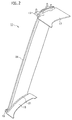
- each vane 11 is a plate-like structure having an airfoil shape for airflow rectification and being elongated in the radial direction.
- a main body of each vane 11 is formed of a carbon fiber reinforced plastic (CFRP) for example. Its outer end is supported by a support structure 13, and its inner end is supported by a similar support structure 15, thereby being fixed to the nacelle 5 and the core portion 7.
- CFRP carbon fiber reinforced plastic
- an outer liner 17 Adjacent to the support structure 13, having its edge in contact with a face of the vane 11, an outer liner 17 is disposed. Similarly, adjacent to the support structure 15, having its edge in contact with the face of the vane 11, an inner liner 19 is disposed. Further in between the vane 11 and the liners 17,19 interposed are seals 21 for respectively sealing intervening gaps.
- the liners 17,19 are respectively formed of CFRP but may be of any different material such as an aluminum alloy.
- Plural combinations of the vanes 11 and the liners 17,19 are arranged circumferentially to meet side by side, thereby constituting a circular structure.
- the plurality of outer liners 17 arranged in a cylindrical shape constitutes a part of the inner wall of the nacelle 5, and the plurality of inner liners 19 similarly constitutes a part of the outer wall of the core portion.
- the outer liners 17 and the inner liners 19 thus define the bypass duct.
- platforms of any aluminum alloy or such are applicable. Generally the platforms get directly in contact with the vanes 11 and these flange portions thereby define the bypass duct.
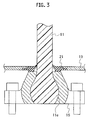
- an inner end 11e of the vane 11 bulges laterally outward in order to reinforce the supportive ability, which is pinched by the support structure 15.
- a bolt hole is opened so as to penetrate the support structure 15 and the inner end 11e, and a bolt 41 is inserted and tightened therein, thereby fixing the inner end 11e and the support structure 15 mutually.
- the support structure 15 has another set of bolt holes 23 in addition, thereby being fixed to the core portion 7.
- the outer end has a similar structure and is thereby fixed to the nacelle 5.
- the leading edge of the main body of the vane 11 is covered with a sheath 31 formed of a proper metal.
- This sheath 31 prevents erosion of the vane 11 by frictional attack by airflow including sand or dust.
- the material applied to the sheath 31 exemplified are, while properly selected in view of erosion resistance and machinability, titanium, titanium alloys, nickel, nickel alloys and stainless steels for example.
- the sheath 31 is made in close contact with the leading edge of the main body of the vane 11 without any gap therebetween, as shown in FIG. 6A .
- This structure with close contact leaving no gap can be realized by any generally known plastic forming but superplastic forming may be instead applicable.
- Some titanium alloys are proper for use of superplastic forming. Further, if possible, any other production method such as casting or machining may be applicable.
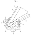
- an electrically conductive pad 33 is provided as if it bridges from the sheath 31 to the bolt 41.
- the electrically conductive pad 33 is formed of a proper metal, and preferably the same material as the sheath 31 is applied thereto. As air sucked by the fan 3 contains a considerable amount of humidity, this portion is placed under a humid condition sufficient to cause corrosion. If an identical material is applied to both the sheath 31 and the electrically conductive pad 33, bimetallic corrosion can be prevented.
- the electrically conductive pad 33 as shown in FIG. 5A , has a leader portion 35, a contact portion 37 elongated upward from its end, and a washer portion 39 elongated downward from another end thereof.
- the contact portion 37 is used for connection with the sheath 31 and the washer portion 39 is used for connection with the bolt 41.
- the contact portion 37 is so dimensioned as to have a proper overlap with the end of the sheath 31.
- the width L1 of the overlap is for example 1 mm or more so as to establish a sufficient contact area, and the length L2 thereof is 10 mm or more.
- both the width L1 and the length L2 are made larger, however, these upper limits are restricted because of its structural factors. For example, if the upper end of the contact portion 37 projects into the bypass duct, it may cause disruption in airflow.
- the width L1 is limited so as to have the upper end not to reach the inner liner 19. Further, as the overlap must not exceed the width of the sheath 31, the length L2 is limited by the width of sheath 31.
- the end of the sheath 31 and the contact portion 37 may be joined together by spot-welding executed by spot-energization.
- spot-welding executed by spot-energization.
- welding, soldering, bonding by an electrically conductive paste, or crimping can be applied thereto.
- the washer portion 39 has a hole into which a bolt is insertable, and a bolt 41 is inserted therein.
- the bolt 41 as passing through the washer portion 39 and being tightened with the support structure 15, establishes electric connection between the electrically conductive pad 33 and the support structure 15.
- it could be connected not with the bolt 41 but with any other bolt such as a bolt tightened in any of the bolt holes 23.
- any joint by soldering or welding is applicable. However, considering that they may be disassembled later for the purpose of inspection, maintenance or repair, connection by tightening is more reasonable.
- the sheath 31 establishes electric connection with the core portion via the electrically conductive pad 33 and the support structure 15. As sufficiently low resistance could be expected at each contact point, electric resistance throughout the conduction path is expected to be sufficiently low.
- the outer end of the vane 11 has a similar conduction structure that establishes electric connection between the sheath 31 and the fan case.
- the fan case and the core portion are thereby mutually electrically connected with low resistance through the sheath 31 and the electrically conductive pad 33, more specifically through the path bypassing the vane main body of CFRP.
- This electric conduction structure may be applied to all of the vanes 11.
- the electric resistance between the fan case and the core portion is reduced down to about several tens or several hundred milliohms. This is sufficiently low resistance to reduce a risk of generating spark. Further, as this is reduced by a factor of ten as compared with that in a case where electric current flows through the vane 11, it could be considered that electric current mainly bypasses the vane main body. This is advantageous in prevention of deterioration of the matrix resin in CFRP.
- the aforementioned embodiment prevents electric current from flowing through the inner liner and the outer liner. Even in a case where they are formed of CFRP, its deterioration is effectively prevented. Further, as the inner liner and the outer liner are not necessary to be used as electric conduction paths, they can be insulated from the vane. In a case where they are formed of an aluminum alloy or such for example, insulation treatments such as anodization could be applied thereto. Even in a case where a distinct metal such as titanium is applied to other members, bimetallic corrosion will not occur. This applies to a case where a platform structure is used instead of the liners.
- an auxiliary electrically conductive wire 37' is applicable thereto.
- the electrically conductive wire 37' is made to pass through a space 11a between the vane main body and the sheath 31 and is joined with the contact portion 37 by means of welding or such. Alternatively this may be directly connected with the bolt 41 or any other bolts. Further alternatively, the electrically conductive wire 37' may be embedded in the vane main body. Such an electrically conductive wire 37' can, in place of or in addition to the sheath 31, function as an electric conduction path having low resistance.
- An electric conduction structure that establishes an electric conductive path with low resistance between a fan case and a core portion, which is capable of conducting and diverting electric current from a vane main body, is provided.
Landscapes
- Engineering & Computer Science (AREA)
- Chemical & Material Sciences (AREA)
- Mechanical Engineering (AREA)
- General Engineering & Computer Science (AREA)
- Combustion & Propulsion (AREA)
- Aviation & Aerospace Engineering (AREA)
- Materials Engineering (AREA)
- Structures Of Non-Positive Displacement Pumps (AREA)
Applications Claiming Priority (2)
| Application Number | Priority Date | Filing Date | Title |
|---|---|---|---|
| JP2013192712A JP6221545B2 (ja) | 2013-09-18 | 2013-09-18 | ジェットエンジンのための導電構造 |
| PCT/JP2014/069337 WO2015040951A1 (ja) | 2013-09-18 | 2014-07-22 | ジェットエンジンのための導電構造 |
Publications (3)
| Publication Number | Publication Date |
|---|---|
| EP3048257A1 true EP3048257A1 (de) | 2016-07-27 |
| EP3048257A4 EP3048257A4 (de) | 2017-04-26 |
| EP3048257B1 EP3048257B1 (de) | 2019-12-11 |
Family
ID=52688610
Family Applications (1)
| Application Number | Title | Priority Date | Filing Date |
|---|---|---|---|
| EP14845967.0A Active EP3048257B1 (de) | 2013-09-18 | 2014-07-22 | Elektrisch leitfähige struktur für triebwerk |
Country Status (7)
| Country | Link |
|---|---|
| US (1) | US10421557B2 (de) |
| EP (1) | EP3048257B1 (de) |
| JP (1) | JP6221545B2 (de) |
| CN (1) | CN105556064B (de) |
| CA (1) | CA2924424C (de) |
| RU (1) | RU2630646C1 (de) |
| WO (1) | WO2015040951A1 (de) |
Families Citing this family (5)
| Publication number | Priority date | Publication date | Assignee | Title |
|---|---|---|---|---|
| US20160298644A1 (en) * | 2013-09-27 | 2016-10-13 | United Technologies Corporation | Fan blade assembly |
| US20160376899A1 (en) * | 2013-11-25 | 2016-12-29 | General Electric Technology Gmbh | Guide vane assembly on the basis of a modular structure |
| JP6417933B2 (ja) | 2014-12-26 | 2018-11-07 | 株式会社Ihi | 円筒状ケース及びジェットエンジン |
| US10640232B2 (en) * | 2016-12-20 | 2020-05-05 | The Boeing Company | Conductive fastening system for composite structures |
| US11988103B2 (en) * | 2021-10-27 | 2024-05-21 | General Electric Company | Airfoils for a fan section of a turbine engine |
Family Cites Families (23)
| Publication number | Priority date | Publication date | Assignee | Title |
|---|---|---|---|---|
| US3762835A (en) * | 1971-07-02 | 1973-10-02 | Gen Electric | Foreign object damage protection for compressor blades and other structures and related methods |
| US3989984A (en) * | 1975-07-11 | 1976-11-02 | Mcdonnell Douglas Corporation | Aircraft lightning protection means |
| DE3815906A1 (de) * | 1988-05-10 | 1989-11-23 | Mtu Muenchen Gmbh | Luftschraubenblatt aus faserverstaerktem kunststoff |
| US5314309A (en) * | 1990-05-25 | 1994-05-24 | Anthony Blakeley | Turbine blade with metallic attachment and method of making the same |
| US5123242A (en) * | 1990-07-30 | 1992-06-23 | General Electric Company | Precooling heat exchange arrangement integral with mounting structure fairing of gas turbine engine |
| US5271714A (en) * | 1992-07-09 | 1993-12-21 | General Electric Company | Turbine nozzle support arrangement |
| US5470442A (en) * | 1994-03-11 | 1995-11-28 | E. I. Du Pont De Nemours And Company | Separating and removing impurities from tetrafluoroethanes by using extractive distillation |
| FR2741590B1 (fr) * | 1995-11-29 | 1998-01-30 | Eurocopter France | Pale a blindage de protection renforcee contre la foudre, pour rotor de giravion |
| JP4162724B2 (ja) * | 1997-06-27 | 2008-10-08 | シーメンス アクチエンゲゼルシヤフト | 内部冷却形蒸気タービンのタービン軸並びにタービン軸の冷却方法 |
| JP2000204902A (ja) | 1999-01-08 | 2000-07-25 | Hitachi Ltd | タ―ビン、タ―ビンロ―タ、及びタ―ビン動翼 |
| JP4860941B2 (ja) | 2005-04-27 | 2012-01-25 | 本田技研工業株式会社 | 整流部材ユニット及びその製造方法 |
| FR2914275B1 (fr) * | 2007-03-27 | 2009-05-22 | Snecma Sa | Support de canalisations sur un aeronef |
| FR2926337B1 (fr) * | 2008-01-14 | 2013-12-06 | Snecma | Aube directrice de sortie pour un turboreacteur d'avion et turboreacteur comportant cette aube |
| FR2934566B1 (fr) | 2008-08-04 | 2011-03-11 | Aircelle Sa | Procede de fabrication d'un ensemble de degivrage sur un panneau d'une nacelle. |
| JP2012527375A (ja) * | 2009-05-19 | 2012-11-08 | エーディーシー アクイジション カンパニー | 落雷保護を有する構造物の形成方法 |
| JP2011051517A (ja) | 2009-09-03 | 2011-03-17 | Mitsubishi Heavy Ind Ltd | 航空機の翼 |
| EP2366871B1 (de) * | 2010-03-17 | 2016-05-11 | General Electric Company | Verfahren und Vorrichtung für eine strukturelle Auslassleitschaufel |
| GB201005053D0 (en) * | 2010-03-26 | 2010-05-12 | Rolls Royce Plc | A gas turbine engine nose cone |
| JP5614131B2 (ja) | 2010-07-01 | 2014-10-29 | 株式会社Ihi | ファン動翼及びファン |
| GB201011228D0 (en) * | 2010-07-05 | 2010-08-18 | Rolls Royce Plc | A composite turbomachine blade |
| US8690531B2 (en) | 2010-12-30 | 2014-04-08 | General Electroc Co. | Vane with spar mounted composite airfoil |
| US8727721B2 (en) * | 2010-12-30 | 2014-05-20 | General Electric Company | Vane with spar mounted composite airfoil |
| GB2498006B (en) * | 2011-12-22 | 2014-07-09 | Rolls Royce Plc | Gas turbine engine systems |
-
2013
- 2013-09-18 JP JP2013192712A patent/JP6221545B2/ja active Active
-
2014
- 2014-07-22 CN CN201480050726.4A patent/CN105556064B/zh not_active Expired - Fee Related
- 2014-07-22 WO PCT/JP2014/069337 patent/WO2015040951A1/ja not_active Ceased
- 2014-07-22 EP EP14845967.0A patent/EP3048257B1/de active Active
- 2014-07-22 CA CA2924424A patent/CA2924424C/en active Active
- 2014-07-22 RU RU2016114271A patent/RU2630646C1/ru active
-
2016
- 2016-03-14 US US15/068,703 patent/US10421557B2/en active Active
Non-Patent Citations (1)
| Title |
|---|
| See references of WO2015040951A1 * |
Also Published As
| Publication number | Publication date |
|---|---|
| EP3048257A4 (de) | 2017-04-26 |
| CN105556064A (zh) | 2016-05-04 |
| EP3048257B1 (de) | 2019-12-11 |
| CN105556064B (zh) | 2017-06-30 |
| JP2015059460A (ja) | 2015-03-30 |
| US20160194091A1 (en) | 2016-07-07 |
| US10421557B2 (en) | 2019-09-24 |
| CA2924424A1 (en) | 2015-03-26 |
| WO2015040951A1 (ja) | 2015-03-26 |
| JP6221545B2 (ja) | 2017-11-01 |
| CA2924424C (en) | 2017-06-20 |
| RU2630646C1 (ru) | 2017-09-11 |
Similar Documents
| Publication | Publication Date | Title |
|---|---|---|
| US10421557B2 (en) | Electric conduction structure for jet engine | |
| US10837295B2 (en) | Fan blade assembly | |
| EP3018363B1 (de) | Statorschaufelstruktur und turbostrahl-düsentriebwerk damit | |
| EP2963289B1 (de) | Windturbinenblatt und reparaturverfahren dafür | |
| EP3049632B1 (de) | Lüfterschaufelanordnung | |
| JP6417933B2 (ja) | 円筒状ケース及びジェットエンジン | |
| US20160230774A1 (en) | Fan blade assembly | |
| EP3049630B1 (de) | Gebläseschaufelanordnung | |
| EP2930306B1 (de) | Bläser eines gasturbinentriebwerks mit diskreten bläserplattformen zur elektrischen erdung von schutzkappen von bläserschaufeln | |
| CA2927602C (en) | VOLTAGE RELIEF PIPE ASSEMBLY FOR A GAS TURBINE |
Legal Events
| Date | Code | Title | Description |
|---|---|---|---|
| PUAI | Public reference made under article 153(3) epc to a published international application that has entered the european phase |
Free format text: ORIGINAL CODE: 0009012 |
|
| 17P | Request for examination filed |
Effective date: 20160331 |
|
| AK | Designated contracting states |
Kind code of ref document: A1 Designated state(s): AL AT BE BG CH CY CZ DE DK EE ES FI FR GB GR HR HU IE IS IT LI LT LU LV MC MK MT NL NO PL PT RO RS SE SI SK SM TR |
|
| AX | Request for extension of the european patent |
Extension state: BA ME |
|
| DAX | Request for extension of the european patent (deleted) | ||
| A4 | Supplementary search report drawn up and despatched |
Effective date: 20170323 |
|
| RIC1 | Information provided on ipc code assigned before grant |
Ipc: F04D 29/54 20060101ALI20170317BHEP Ipc: F01D 9/02 20060101AFI20170317BHEP Ipc: F02C 7/00 20060101ALI20170317BHEP |
|
| STAA | Information on the status of an ep patent application or granted ep patent |
Free format text: STATUS: EXAMINATION IS IN PROGRESS |
|
| 17Q | First examination report despatched |
Effective date: 20181123 |
|
| GRAP | Despatch of communication of intention to grant a patent |
Free format text: ORIGINAL CODE: EPIDOSNIGR1 |
|
| STAA | Information on the status of an ep patent application or granted ep patent |
Free format text: STATUS: GRANT OF PATENT IS INTENDED |
|
| INTG | Intention to grant announced |
Effective date: 20190626 |
|
| GRAS | Grant fee paid |
Free format text: ORIGINAL CODE: EPIDOSNIGR3 |
|
| GRAA | (expected) grant |
Free format text: ORIGINAL CODE: 0009210 |
|
| STAA | Information on the status of an ep patent application or granted ep patent |
Free format text: STATUS: THE PATENT HAS BEEN GRANTED |
|
| AK | Designated contracting states |
Kind code of ref document: B1 Designated state(s): AL AT BE BG CH CY CZ DE DK EE ES FI FR GB GR HR HU IE IS IT LI LT LU LV MC MK MT NL NO PL PT RO RS SE SI SK SM TR |
|
| REG | Reference to a national code |
Ref country code: GB Ref legal event code: FG4D |
|
| REG | Reference to a national code |
Ref country code: CH Ref legal event code: EP |
|
| REG | Reference to a national code |
Ref country code: AT Ref legal event code: REF Ref document number: 1212383 Country of ref document: AT Kind code of ref document: T Effective date: 20191215 |
|
| REG | Reference to a national code |
Ref country code: DE Ref legal event code: R096 Ref document number: 602014058367 Country of ref document: DE |
|
| REG | Reference to a national code |
Ref country code: IE Ref legal event code: FG4D |
|
| REG | Reference to a national code |
Ref country code: NL Ref legal event code: MP Effective date: 20191211 |
|
| REG | Reference to a national code |
Ref country code: LT Ref legal event code: MG4D |
|
| PG25 | Lapsed in a contracting state [announced via postgrant information from national office to epo] |
Ref country code: NO Free format text: LAPSE BECAUSE OF FAILURE TO SUBMIT A TRANSLATION OF THE DESCRIPTION OR TO PAY THE FEE WITHIN THE PRESCRIBED TIME-LIMIT Effective date: 20200311 Ref country code: GR Free format text: LAPSE BECAUSE OF FAILURE TO SUBMIT A TRANSLATION OF THE DESCRIPTION OR TO PAY THE FEE WITHIN THE PRESCRIBED TIME-LIMIT Effective date: 20200312 Ref country code: BG Free format text: LAPSE BECAUSE OF FAILURE TO SUBMIT A TRANSLATION OF THE DESCRIPTION OR TO PAY THE FEE WITHIN THE PRESCRIBED TIME-LIMIT Effective date: 20200311 Ref country code: LT Free format text: LAPSE BECAUSE OF FAILURE TO SUBMIT A TRANSLATION OF THE DESCRIPTION OR TO PAY THE FEE WITHIN THE PRESCRIBED TIME-LIMIT Effective date: 20191211 Ref country code: SE Free format text: LAPSE BECAUSE OF FAILURE TO SUBMIT A TRANSLATION OF THE DESCRIPTION OR TO PAY THE FEE WITHIN THE PRESCRIBED TIME-LIMIT Effective date: 20191211 Ref country code: LV Free format text: LAPSE BECAUSE OF FAILURE TO SUBMIT A TRANSLATION OF THE DESCRIPTION OR TO PAY THE FEE WITHIN THE PRESCRIBED TIME-LIMIT Effective date: 20191211 Ref country code: FI Free format text: LAPSE BECAUSE OF FAILURE TO SUBMIT A TRANSLATION OF THE DESCRIPTION OR TO PAY THE FEE WITHIN THE PRESCRIBED TIME-LIMIT Effective date: 20191211 |
|
| PG25 | Lapsed in a contracting state [announced via postgrant information from national office to epo] |
Ref country code: RS Free format text: LAPSE BECAUSE OF FAILURE TO SUBMIT A TRANSLATION OF THE DESCRIPTION OR TO PAY THE FEE WITHIN THE PRESCRIBED TIME-LIMIT Effective date: 20191211 Ref country code: HR Free format text: LAPSE BECAUSE OF FAILURE TO SUBMIT A TRANSLATION OF THE DESCRIPTION OR TO PAY THE FEE WITHIN THE PRESCRIBED TIME-LIMIT Effective date: 20191211 |
|
| PG25 | Lapsed in a contracting state [announced via postgrant information from national office to epo] |
Ref country code: AL Free format text: LAPSE BECAUSE OF FAILURE TO SUBMIT A TRANSLATION OF THE DESCRIPTION OR TO PAY THE FEE WITHIN THE PRESCRIBED TIME-LIMIT Effective date: 20191211 |
|
| PG25 | Lapsed in a contracting state [announced via postgrant information from national office to epo] |
Ref country code: ES Free format text: LAPSE BECAUSE OF FAILURE TO SUBMIT A TRANSLATION OF THE DESCRIPTION OR TO PAY THE FEE WITHIN THE PRESCRIBED TIME-LIMIT Effective date: 20191211 Ref country code: PT Free format text: LAPSE BECAUSE OF FAILURE TO SUBMIT A TRANSLATION OF THE DESCRIPTION OR TO PAY THE FEE WITHIN THE PRESCRIBED TIME-LIMIT Effective date: 20200506 Ref country code: EE Free format text: LAPSE BECAUSE OF FAILURE TO SUBMIT A TRANSLATION OF THE DESCRIPTION OR TO PAY THE FEE WITHIN THE PRESCRIBED TIME-LIMIT Effective date: 20191211 Ref country code: CZ Free format text: LAPSE BECAUSE OF FAILURE TO SUBMIT A TRANSLATION OF THE DESCRIPTION OR TO PAY THE FEE WITHIN THE PRESCRIBED TIME-LIMIT Effective date: 20191211 Ref country code: RO Free format text: LAPSE BECAUSE OF FAILURE TO SUBMIT A TRANSLATION OF THE DESCRIPTION OR TO PAY THE FEE WITHIN THE PRESCRIBED TIME-LIMIT Effective date: 20191211 Ref country code: NL Free format text: LAPSE BECAUSE OF FAILURE TO SUBMIT A TRANSLATION OF THE DESCRIPTION OR TO PAY THE FEE WITHIN THE PRESCRIBED TIME-LIMIT Effective date: 20191211 |
|
| PG25 | Lapsed in a contracting state [announced via postgrant information from national office to epo] |
Ref country code: IS Free format text: LAPSE BECAUSE OF FAILURE TO SUBMIT A TRANSLATION OF THE DESCRIPTION OR TO PAY THE FEE WITHIN THE PRESCRIBED TIME-LIMIT Effective date: 20200411 Ref country code: SK Free format text: LAPSE BECAUSE OF FAILURE TO SUBMIT A TRANSLATION OF THE DESCRIPTION OR TO PAY THE FEE WITHIN THE PRESCRIBED TIME-LIMIT Effective date: 20191211 Ref country code: SM Free format text: LAPSE BECAUSE OF FAILURE TO SUBMIT A TRANSLATION OF THE DESCRIPTION OR TO PAY THE FEE WITHIN THE PRESCRIBED TIME-LIMIT Effective date: 20191211 |
|
| REG | Reference to a national code |
Ref country code: DE Ref legal event code: R097 Ref document number: 602014058367 Country of ref document: DE |
|
| REG | Reference to a national code |
Ref country code: AT Ref legal event code: MK05 Ref document number: 1212383 Country of ref document: AT Kind code of ref document: T Effective date: 20191211 |
|
| PLBE | No opposition filed within time limit |
Free format text: ORIGINAL CODE: 0009261 |
|
| STAA | Information on the status of an ep patent application or granted ep patent |
Free format text: STATUS: NO OPPOSITION FILED WITHIN TIME LIMIT |
|
| PG25 | Lapsed in a contracting state [announced via postgrant information from national office to epo] |
Ref country code: DK Free format text: LAPSE BECAUSE OF FAILURE TO SUBMIT A TRANSLATION OF THE DESCRIPTION OR TO PAY THE FEE WITHIN THE PRESCRIBED TIME-LIMIT Effective date: 20191211 |
|
| 26N | No opposition filed |
Effective date: 20200914 |
|
| PG25 | Lapsed in a contracting state [announced via postgrant information from national office to epo] |
Ref country code: SI Free format text: LAPSE BECAUSE OF FAILURE TO SUBMIT A TRANSLATION OF THE DESCRIPTION OR TO PAY THE FEE WITHIN THE PRESCRIBED TIME-LIMIT Effective date: 20191211 Ref country code: AT Free format text: LAPSE BECAUSE OF FAILURE TO SUBMIT A TRANSLATION OF THE DESCRIPTION OR TO PAY THE FEE WITHIN THE PRESCRIBED TIME-LIMIT Effective date: 20191211 |
|
| PG25 | Lapsed in a contracting state [announced via postgrant information from national office to epo] |
Ref country code: PL Free format text: LAPSE BECAUSE OF FAILURE TO SUBMIT A TRANSLATION OF THE DESCRIPTION OR TO PAY THE FEE WITHIN THE PRESCRIBED TIME-LIMIT Effective date: 20191211 Ref country code: MC Free format text: LAPSE BECAUSE OF FAILURE TO SUBMIT A TRANSLATION OF THE DESCRIPTION OR TO PAY THE FEE WITHIN THE PRESCRIBED TIME-LIMIT Effective date: 20191211 |
|
| REG | Reference to a national code |
Ref country code: CH Ref legal event code: PL |
|
| REG | Reference to a national code |
Ref country code: BE Ref legal event code: MM Effective date: 20200731 |
|
| PG25 | Lapsed in a contracting state [announced via postgrant information from national office to epo] |
Ref country code: CH Free format text: LAPSE BECAUSE OF NON-PAYMENT OF DUE FEES Effective date: 20200731 Ref country code: LU Free format text: LAPSE BECAUSE OF NON-PAYMENT OF DUE FEES Effective date: 20200722 Ref country code: LI Free format text: LAPSE BECAUSE OF NON-PAYMENT OF DUE FEES Effective date: 20200731 |
|
| PG25 | Lapsed in a contracting state [announced via postgrant information from national office to epo] |
Ref country code: BE Free format text: LAPSE BECAUSE OF NON-PAYMENT OF DUE FEES Effective date: 20200731 |
|
| PG25 | Lapsed in a contracting state [announced via postgrant information from national office to epo] |
Ref country code: IE Free format text: LAPSE BECAUSE OF NON-PAYMENT OF DUE FEES Effective date: 20200722 |
|
| PG25 | Lapsed in a contracting state [announced via postgrant information from national office to epo] |
Ref country code: TR Free format text: LAPSE BECAUSE OF FAILURE TO SUBMIT A TRANSLATION OF THE DESCRIPTION OR TO PAY THE FEE WITHIN THE PRESCRIBED TIME-LIMIT Effective date: 20191211 Ref country code: MT Free format text: LAPSE BECAUSE OF FAILURE TO SUBMIT A TRANSLATION OF THE DESCRIPTION OR TO PAY THE FEE WITHIN THE PRESCRIBED TIME-LIMIT Effective date: 20191211 Ref country code: CY Free format text: LAPSE BECAUSE OF FAILURE TO SUBMIT A TRANSLATION OF THE DESCRIPTION OR TO PAY THE FEE WITHIN THE PRESCRIBED TIME-LIMIT Effective date: 20191211 |
|
| PG25 | Lapsed in a contracting state [announced via postgrant information from national office to epo] |
Ref country code: MK Free format text: LAPSE BECAUSE OF FAILURE TO SUBMIT A TRANSLATION OF THE DESCRIPTION OR TO PAY THE FEE WITHIN THE PRESCRIBED TIME-LIMIT Effective date: 20191211 |
|
| PGFP | Annual fee paid to national office [announced via postgrant information from national office to epo] |
Ref country code: IT Payment date: 20220621 Year of fee payment: 9 |
|
| PGFP | Annual fee paid to national office [announced via postgrant information from national office to epo] |
Ref country code: FR Payment date: 20220621 Year of fee payment: 9 |
|
| PG25 | Lapsed in a contracting state [announced via postgrant information from national office to epo] |
Ref country code: FR Free format text: LAPSE BECAUSE OF NON-PAYMENT OF DUE FEES Effective date: 20230731 |
|
| PG25 | Lapsed in a contracting state [announced via postgrant information from national office to epo] |
Ref country code: IT Free format text: LAPSE BECAUSE OF NON-PAYMENT OF DUE FEES Effective date: 20230722 |
|
| PGFP | Annual fee paid to national office [announced via postgrant information from national office to epo] |
Ref country code: GB Payment date: 20250619 Year of fee payment: 12 |
|
| PGFP | Annual fee paid to national office [announced via postgrant information from national office to epo] |
Ref country code: DE Payment date: 20250620 Year of fee payment: 12 |