EP3048377B1 - Klimaanlage und verfahren zur steuerung einer klimaanlage - Google Patents
Klimaanlage und verfahren zur steuerung einer klimaanlage Download PDFInfo
- Publication number
- EP3048377B1 EP3048377B1 EP16150602.7A EP16150602A EP3048377B1 EP 3048377 B1 EP3048377 B1 EP 3048377B1 EP 16150602 A EP16150602 A EP 16150602A EP 3048377 B1 EP3048377 B1 EP 3048377B1
- Authority
- EP
- European Patent Office
- Prior art keywords
- balancing
- heat exchanger
- air conditioner
- pipe
- flow rate
- Prior art date
- Legal status (The legal status is an assumption and is not a legal conclusion. Google has not performed a legal analysis and makes no representation as to the accuracy of the status listed.)
- Not-in-force
Links
Images


Classifications
-
- F—MECHANICAL ENGINEERING; LIGHTING; HEATING; WEAPONS; BLASTING
- F24—HEATING; RANGES; VENTILATING
- F24F—AIR-CONDITIONING; AIR-HUMIDIFICATION; VENTILATION; USE OF AIR CURRENTS FOR SCREENING
- F24F1/00—Room units for air-conditioning, e.g. separate or self-contained units or units receiving primary air from a central station
- F24F1/06—Separate outdoor units, e.g. outdoor unit to be linked to a separate room comprising a compressor and a heat exchanger
- F24F1/44—Separate outdoor units, e.g. outdoor unit to be linked to a separate room comprising a compressor and a heat exchanger characterised by the use of internal combustion engines
-
- F—MECHANICAL ENGINEERING; LIGHTING; HEATING; WEAPONS; BLASTING
- F25—REFRIGERATION OR COOLING; COMBINED HEATING AND REFRIGERATION SYSTEMS; HEAT PUMP SYSTEMS; MANUFACTURE OR STORAGE OF ICE; LIQUEFACTION SOLIDIFICATION OF GASES
- F25B—REFRIGERATION MACHINES, PLANTS OR SYSTEMS; COMBINED HEATING AND REFRIGERATION SYSTEMS; HEAT PUMP SYSTEMS
- F25B47/00—Arrangements for preventing or removing deposits or corrosion, not provided for in another subclass
- F25B47/02—Defrosting cycles
- F25B47/022—Defrosting cycles hot gas defrosting
- F25B47/025—Defrosting cycles hot gas defrosting by reversing the cycle
-
- F—MECHANICAL ENGINEERING; LIGHTING; HEATING; WEAPONS; BLASTING
- F24—HEATING; RANGES; VENTILATING
- F24F—AIR-CONDITIONING; AIR-HUMIDIFICATION; VENTILATION; USE OF AIR CURRENTS FOR SCREENING
- F24F1/00—Room units for air-conditioning, e.g. separate or self-contained units or units receiving primary air from a central station
- F24F1/06—Separate outdoor units, e.g. outdoor unit to be linked to a separate room comprising a compressor and a heat exchanger
- F24F1/08—Compressors specially adapted for separate outdoor units
-
- F—MECHANICAL ENGINEERING; LIGHTING; HEATING; WEAPONS; BLASTING
- F24—HEATING; RANGES; VENTILATING
- F24F—AIR-CONDITIONING; AIR-HUMIDIFICATION; VENTILATION; USE OF AIR CURRENTS FOR SCREENING
- F24F1/00—Room units for air-conditioning, e.g. separate or self-contained units or units receiving primary air from a central station
- F24F1/06—Separate outdoor units, e.g. outdoor unit to be linked to a separate room comprising a compressor and a heat exchanger
- F24F1/14—Heat exchangers specially adapted for separate outdoor units
-
- F—MECHANICAL ENGINEERING; LIGHTING; HEATING; WEAPONS; BLASTING
- F24—HEATING; RANGES; VENTILATING
- F24F—AIR-CONDITIONING; AIR-HUMIDIFICATION; VENTILATION; USE OF AIR CURRENTS FOR SCREENING
- F24F11/00—Control or safety arrangements
- F24F11/70—Control systems characterised by their outputs; Constructional details thereof
- F24F11/72—Control systems characterised by their outputs; Constructional details thereof for controlling the supply of treated air, e.g. its pressure
-
- F—MECHANICAL ENGINEERING; LIGHTING; HEATING; WEAPONS; BLASTING
- F24—HEATING; RANGES; VENTILATING
- F24F—AIR-CONDITIONING; AIR-HUMIDIFICATION; VENTILATION; USE OF AIR CURRENTS FOR SCREENING
- F24F11/00—Control or safety arrangements
- F24F11/70—Control systems characterised by their outputs; Constructional details thereof
- F24F11/80—Control systems characterised by their outputs; Constructional details thereof for controlling the temperature of the supplied air
- F24F11/83—Control systems characterised by their outputs; Constructional details thereof for controlling the temperature of the supplied air by controlling the supply of heat-exchange fluids to heat-exchangers
-
- F—MECHANICAL ENGINEERING; LIGHTING; HEATING; WEAPONS; BLASTING
- F24—HEATING; RANGES; VENTILATING
- F24F—AIR-CONDITIONING; AIR-HUMIDIFICATION; VENTILATION; USE OF AIR CURRENTS FOR SCREENING
- F24F11/00—Control or safety arrangements
- F24F11/70—Control systems characterised by their outputs; Constructional details thereof
- F24F11/80—Control systems characterised by their outputs; Constructional details thereof for controlling the temperature of the supplied air
- F24F11/83—Control systems characterised by their outputs; Constructional details thereof for controlling the temperature of the supplied air by controlling the supply of heat-exchange fluids to heat-exchangers
- F24F11/84—Control systems characterised by their outputs; Constructional details thereof for controlling the temperature of the supplied air by controlling the supply of heat-exchange fluids to heat-exchangers using valves
-
- F—MECHANICAL ENGINEERING; LIGHTING; HEATING; WEAPONS; BLASTING
- F25—REFRIGERATION OR COOLING; COMBINED HEATING AND REFRIGERATION SYSTEMS; HEAT PUMP SYSTEMS; MANUFACTURE OR STORAGE OF ICE; LIQUEFACTION SOLIDIFICATION OF GASES
- F25B—REFRIGERATION MACHINES, PLANTS OR SYSTEMS; COMBINED HEATING AND REFRIGERATION SYSTEMS; HEAT PUMP SYSTEMS
- F25B13/00—Compression machines, plants or systems, with reversible cycle
-
- F—MECHANICAL ENGINEERING; LIGHTING; HEATING; WEAPONS; BLASTING
- F25—REFRIGERATION OR COOLING; COMBINED HEATING AND REFRIGERATION SYSTEMS; HEAT PUMP SYSTEMS; MANUFACTURE OR STORAGE OF ICE; LIQUEFACTION SOLIDIFICATION OF GASES
- F25B—REFRIGERATION MACHINES, PLANTS OR SYSTEMS; COMBINED HEATING AND REFRIGERATION SYSTEMS; HEAT PUMP SYSTEMS
- F25B27/00—Machines, plants or systems, using particular sources of energy
- F25B27/02—Machines, plants or systems, using particular sources of energy using waste heat, e.g. from internal-combustion engines
-
- F—MECHANICAL ENGINEERING; LIGHTING; HEATING; WEAPONS; BLASTING
- F25—REFRIGERATION OR COOLING; COMBINED HEATING AND REFRIGERATION SYSTEMS; HEAT PUMP SYSTEMS; MANUFACTURE OR STORAGE OF ICE; LIQUEFACTION SOLIDIFICATION OF GASES
- F25B—REFRIGERATION MACHINES, PLANTS OR SYSTEMS; COMBINED HEATING AND REFRIGERATION SYSTEMS; HEAT PUMP SYSTEMS
- F25B45/00—Arrangements for charging or discharging refrigerant
-
- F—MECHANICAL ENGINEERING; LIGHTING; HEATING; WEAPONS; BLASTING
- F24—HEATING; RANGES; VENTILATING
- F24F—AIR-CONDITIONING; AIR-HUMIDIFICATION; VENTILATION; USE OF AIR CURRENTS FOR SCREENING
- F24F2110/00—Control inputs relating to air properties
- F24F2110/40—Pressure, e.g. wind pressure
-
- F—MECHANICAL ENGINEERING; LIGHTING; HEATING; WEAPONS; BLASTING
- F24—HEATING; RANGES; VENTILATING
- F24F—AIR-CONDITIONING; AIR-HUMIDIFICATION; VENTILATION; USE OF AIR CURRENTS FOR SCREENING
- F24F2140/00—Control inputs relating to system states
- F24F2140/10—Pressure
- F24F2140/12—Heat-exchange fluid pressure
-
- F—MECHANICAL ENGINEERING; LIGHTING; HEATING; WEAPONS; BLASTING
- F25—REFRIGERATION OR COOLING; COMBINED HEATING AND REFRIGERATION SYSTEMS; HEAT PUMP SYSTEMS; MANUFACTURE OR STORAGE OF ICE; LIQUEFACTION SOLIDIFICATION OF GASES
- F25B—REFRIGERATION MACHINES, PLANTS OR SYSTEMS; COMBINED HEATING AND REFRIGERATION SYSTEMS; HEAT PUMP SYSTEMS
- F25B2313/00—Compression machines, plants or systems with reversible cycle not otherwise provided for
- F25B2313/025—Compression machines, plants or systems with reversible cycle not otherwise provided for using multiple outdoor units
- F25B2313/0253—Compression machines, plants or systems with reversible cycle not otherwise provided for using multiple outdoor units in parallel arrangements
-
- F—MECHANICAL ENGINEERING; LIGHTING; HEATING; WEAPONS; BLASTING
- F25—REFRIGERATION OR COOLING; COMBINED HEATING AND REFRIGERATION SYSTEMS; HEAT PUMP SYSTEMS; MANUFACTURE OR STORAGE OF ICE; LIQUEFACTION SOLIDIFICATION OF GASES
- F25B—REFRIGERATION MACHINES, PLANTS OR SYSTEMS; COMBINED HEATING AND REFRIGERATION SYSTEMS; HEAT PUMP SYSTEMS
- F25B2313/00—Compression machines, plants or systems with reversible cycle not otherwise provided for
- F25B2313/025—Compression machines, plants or systems with reversible cycle not otherwise provided for using multiple outdoor units
- F25B2313/0253—Compression machines, plants or systems with reversible cycle not otherwise provided for using multiple outdoor units in parallel arrangements
- F25B2313/02532—Compression machines, plants or systems with reversible cycle not otherwise provided for using multiple outdoor units in parallel arrangements during defrosting
-
- F—MECHANICAL ENGINEERING; LIGHTING; HEATING; WEAPONS; BLASTING
- F25—REFRIGERATION OR COOLING; COMBINED HEATING AND REFRIGERATION SYSTEMS; HEAT PUMP SYSTEMS; MANUFACTURE OR STORAGE OF ICE; LIQUEFACTION SOLIDIFICATION OF GASES
- F25B—REFRIGERATION MACHINES, PLANTS OR SYSTEMS; COMBINED HEATING AND REFRIGERATION SYSTEMS; HEAT PUMP SYSTEMS
- F25B2313/00—Compression machines, plants or systems with reversible cycle not otherwise provided for
- F25B2313/027—Compression machines, plants or systems with reversible cycle not otherwise provided for characterised by the reversing means
- F25B2313/02742—Compression machines, plants or systems with reversible cycle not otherwise provided for characterised by the reversing means using two four-way valves
-
- F25B2327/001—
-
- F—MECHANICAL ENGINEERING; LIGHTING; HEATING; WEAPONS; BLASTING
- F25—REFRIGERATION OR COOLING; COMBINED HEATING AND REFRIGERATION SYSTEMS; HEAT PUMP SYSTEMS; MANUFACTURE OR STORAGE OF ICE; LIQUEFACTION SOLIDIFICATION OF GASES
- F25B—REFRIGERATION MACHINES, PLANTS OR SYSTEMS; COMBINED HEATING AND REFRIGERATION SYSTEMS; HEAT PUMP SYSTEMS
- F25B2327/00—Compressor driving means
- F25B2327/10—Compressor driving means using engines
- F25B2327/12—Compressor driving means using engines using internal combustion engines
-
- F—MECHANICAL ENGINEERING; LIGHTING; HEATING; WEAPONS; BLASTING
- F25—REFRIGERATION OR COOLING; COMBINED HEATING AND REFRIGERATION SYSTEMS; HEAT PUMP SYSTEMS; MANUFACTURE OR STORAGE OF ICE; LIQUEFACTION SOLIDIFICATION OF GASES
- F25B—REFRIGERATION MACHINES, PLANTS OR SYSTEMS; COMBINED HEATING AND REFRIGERATION SYSTEMS; HEAT PUMP SYSTEMS
- F25B2600/00—Control issues
- F25B2600/25—Control of valves
- F25B2600/2515—Flow valves
-
- F—MECHANICAL ENGINEERING; LIGHTING; HEATING; WEAPONS; BLASTING
- F25—REFRIGERATION OR COOLING; COMBINED HEATING AND REFRIGERATION SYSTEMS; HEAT PUMP SYSTEMS; MANUFACTURE OR STORAGE OF ICE; LIQUEFACTION SOLIDIFICATION OF GASES
- F25B—REFRIGERATION MACHINES, PLANTS OR SYSTEMS; COMBINED HEATING AND REFRIGERATION SYSTEMS; HEAT PUMP SYSTEMS
- F25B2700/00—Sensing or detecting of parameters; Sensors therefor
- F25B2700/13—Mass flow of refrigerants
- F25B2700/135—Mass flow of refrigerants through the evaporator
- F25B2700/1353—Mass flow of refrigerants through the evaporator at the outlet
-
- Y—GENERAL TAGGING OF NEW TECHNOLOGICAL DEVELOPMENTS; GENERAL TAGGING OF CROSS-SECTIONAL TECHNOLOGIES SPANNING OVER SEVERAL SECTIONS OF THE IPC; TECHNICAL SUBJECTS COVERED BY FORMER USPC CROSS-REFERENCE ART COLLECTIONS [XRACs] AND DIGESTS
- Y02—TECHNOLOGIES OR APPLICATIONS FOR MITIGATION OR ADAPTATION AGAINST CLIMATE CHANGE
- Y02A—TECHNOLOGIES FOR ADAPTATION TO CLIMATE CHANGE
- Y02A30/00—Adapting or protecting infrastructure or their operation
- Y02A30/27—Relating to heating, ventilation or air conditioning [HVAC] technologies
- Y02A30/274—Relating to heating, ventilation or air conditioning [HVAC] technologies using waste energy, e.g. from internal combustion engine
Definitions
- An air conditioner is an apparatus that cools, warms, or purifies indoor air to provide a more comfortable indoor environment for a user.
- An air conditioner may be classified as an electric heat pump (EHP) type, which uses electric power or a gas heat pump (GHP) type, which uses a gas fuel, such as liquid petroleum gas (LPG) and liquefied natural gas (LNG), according to a power source for driving a compressor.
- EHP electric heat pump
- GHP gas heat pump
- LPG liquid petroleum gas
- LNG liquefied natural gas
- a conventional EHP type air conditioner is disclosed in Korean Patent Application No. 10-2003-0077857 , which is hereby incorporated by reference.
- the compressor may be easily controlled by adjusting a supply current, it is as to respond to a partial load, and thus, the conventional EHP type air conditioner has high energy efficiency.
- the EHP type air conditioner there is a problem in that an outdoor heat exchanger is covered with frost when low temperature warming is performed.
- a conventional GHP type air conditioner is also disclosed in Korean Patent Application No. 10-2003-0077857 .
- FIG. 1 schematic diagram of an air conditioner according to an embodiment.
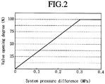
- Fig. 2 is a graph showing valve open degree versus system pressure difference of a flow rate balancing valve of the air conditioner of Fig. 1 .
- Fig. 3 is a graph illustrating system efficiency in a partial load operation of the air conditioner of Fig. 1 .
- the air conditioner 1 may include an indoor unit or device 10 and an outdoor unit or device 100.
- One or a plurality of indoor units 10 may be provided.
- the one or more indoor units 10 may be connected with the outdoor unit 100, and may cool, warm, or purify indoor air.
- the outdoor unit 100 may be connected with the one or more indoor unit 10, and may perform compressing and expanding, for example, of a refrigerant to allow a sufficient heat exchanging operation of the indoor unit 10.
- a plurality of outdoor units 100 may be provided.
- an embodiment having one pair of outdoor units 100 will be described.
- the outdoor unit 100 may be a combined type including an electric heat pump (EHP) type using electric power and a gas heat pump (GHP) type using a gas fuel, such as LPG and LNG.
- the outdoor unit 100 may include an EHP outdoor unit or device 200, a GHP outdoor unit or device 300, and a flow rate balancing unit or device 500.
- the EHP outdoor unit 200 may be an outdoor unit operated using an EHP, and may include a first compressor 210, a first heat exchanger 250, a first expansion valve 260, and a first four-way valve 290.
- the first compressor 210 may compress the refrigerant, and may be driven by applying a voltage. That is, when the voltage is applied to the first compressor 210, the first compressor 210 may compress the refrigerant.
- the first heat exchanger 250 may be an outdoor heat exchanger, and may evaporate or condense the refrigerant according to a cooling operation or a warming operations of the air conditioner 1. When the air conditioner 1 performs the cooling operation, the refrigerant may be condensed, and when the air conditioner 1 performs the warming operation, the refrigerant may be evaporated.
- the expansion valve 260 may control a flow of the refrigerant to the first heat exchanger 250.
- the first expansion valve 260 is well known, detailed description thereof has been omitted.
- the first four-way valve 290 may switch a passage of the refrigerant flowing in the EHP outdoor unit 200.
- the first four-way valve 290 may switch a passage of the refrigerant flowing to the indoor unit 10 and the refrigerant introduced from the indoor unit 10.
- the GHP outdoor unit 300 may be an outdoor unit operated using a GHP method, and may include a second compressor 310, an engine 330, a second heat exchanger 350, a second expansion valve 360, a waste heat recovery heat exchanger 370, a cooling water pump 380, and a second four-way valve 390.
- the second compressor 310 may compress the refrigerant, and may be operated through driving of the engine 330, which will be described hereinafter. When a drive force is transmitted to the second compressor 310 by the engine 330, the second compressor 310 may compress the refrigerant, similar to the first compressor 210.
- the engine 330 may transmit the drive force to the second compressor 310, and may be operated through burning of the gas fuel, such as LPG and LNG.
- the GHP outdoor unit 300 may be operated using the GHP method using the burned gas from the engine 330.
- the second heat exchanger 350 may be an outdoor heat exchanger, similar to the first heat exchanger 250, and may also be an evaporate or condense the refrigerant according to operation or the cooling the warming operation of the air conditioner 1. When the air conditioner 1 performs the cooling operation, the refrigerant may be condensed, and when the air conditioner 1 performs the warming operation, the refrigerant may be evaporated.
- the second expansion valve 360 may control a flow of the refrigerant to the second heat exchanger 350.
- the waste heat recovery heat exchanger 370 may be a heat exchanger that uses waste heat of the engine 330.
- the waste heat recovery heat exchanger 370 may absorb heat of the engine 330 overheated by driving of the engine 330 using cooling water, and thus, may cool the engine 330.
- the cooling water pump 380 may provide a flowing force for the cooling water, and may be connected with the waste heat recovery heat exchanger 370. Therefore, the cooling water pump 380 may supply the cooling water to the waste heat recovery heat exchanger 370.
- the second four-way valve 390 may switch a passage of the refrigerant flowing in the GHP outdoor unit 300.
- the second four-way valve 380 may switch a passage of the refrigerant flowing to the indoor unit 10 and the refrigerant introduced from the indoor unit 10.
- the flow rate balancing unit 500 may connect the first heat exchanger 250 with the second heat exchanger 350, and may control a flow rate of the refrigerant of the EHP outdoor unit 200 and the GHP outdoor unit 300. Therefore, in this embodiment, when the EHP outdoor unit 200 and the GHP outdoor unit 300 are operated at a same time, a flow rate balance generated due to a pressure difference between both systems may be controlled through or by the flow rate balancing unit 500.
- the flow rate balancing unit 500 may include a balancing pipe 510, a balancing valve 520, and a plurality of balancing sensors 530 and 540.
- the balancing pipe 510 may connect the first heat exchanger 250 of the EHP outdoor unit 200 with the second heat exchanger 350 of the GHP outdoor unit 300.
- the balancing pipe 510 may include a first pipe 512, a second pipe 514, and the third pipe 516.
- the first pipe 512 may be connected with the first heat exchanger 250 of the EHP outdoor unit 200.
- the second pipe 514 may be connected with the second heat exchanger 350 of the GHP outdoor unit 300.
- the third pipe 516 may connect the first pipe 512 with the second pipe 514.
- the balancing valve 520 may be provided at or in the balancing pipe 510, and may include a valve, an opening degree of which may be varied to control the flow rate.
- the balancing valve 520 may be provided at or in the third pipe 516 of the balancing pipe 510, and may be provided at the GHP outdoor unit 300 side.
- the opening degree of the balancing valve 520 may be proportional to a pressure difference between systems, that is, a pressure difference between the EHP outdoor unit 200 and the GHP outdoor unit 300.
- the balancing valve 520 may be completely opened.
- the opening degree of the balancing valve 520 may be properly controlled according to the pressure difference between the outdoor units 200 and 300, and thus, may control the flow rate balance appropriately.
- the plurality of balancing sensors 530 and 540 may be pressure sensors that measure a pressure and may be provided at or in the balancing pipe 510.
- pressure sensors that measure a pressure
- the plurality of balancing sensors 530 and 540 may be pressure sensors that measure a pressure and may be provided at or in the balancing pipe 510.
- an embodiment in which one pair of balancing sensors is provided will be described, as an example.
- the pair of balancing sensors 530 and 540 may include a first sensor 530 and a second sensor 540.
- the first sensor 530 may be provided at or in the first pipe 512, and may be provided close to the first heat exchanger 250.
- the second sensor 540 may be provided at or in the second pipe 514, and may be provided close to the second heat exchanger 350.
- the pressure of the EHP outdoor unit 200 and the GHP outdoor unit 300 may be measured by the first and second sensors 530 and 540, respectively.
- the air conditioner 1 may measure a pressure difference between the outdoor units 200 and 300 generated during an operation thereof via the flow rate balancing unit 500 in real time, and may control the flow rate balance in real time by properly changing the opening degree of the balancing valve 520.
- the air conditioner 1 when only one of the EHP outdoor unit 200 and the GHP outdoor unit 300 is operated, the air conditioner 1 according to an embodiment may open the balancing valve 520 of the flow rate balancing unit 500 and may use both of the first and second heat exchangers 250 and 350.
- both of the heat exchangers of the EHP outdoor unit 200 and the GHP outdoor unit 300 may be used in this embodiment, and thus, it may be possible to obtain an effect of expanding the heat exchanger.
- a condensing pressure may be reduced, and thus, a load in driving of the compressor may also be reduced, and a coeffectiveness of performance may be maximally enhanced by about 30%.
- a system efficiency of the air conditioner 1 may be maximally enhanced by about 30% in a partial load operation.
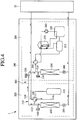
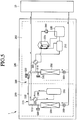
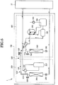
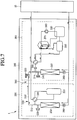
- FIGS. 4 to 7 are schematic diagrams illustrating a flow of a refrigerant according to a single operation mode of the air conditioner of Fig. 1 .
- a dotted line arrow may represent a low pressure refrigerant
- a solid line arrow may represent a high pressure refrigerant
- Fig. 4 illustrates the flow of the refrigerant when only the EHP outdoor unit 200 performs the cooling operation.
- the low pressure refrigerant introduced from the indoor unit 10 may be introduced into the first compressor 210 of the EHP outdoor unit 200 via the first four-way valve 290 of the EHP outdoor unit 200.
- the high pressure refrigerant compressed by the first compressor 210 of the EHP outdoor unit 200 may then be branched toward the first heat exchanger 250 and the balancing pipe 510 of the flow rate balancing unit 500 via the first four-way valve 290.
- the high pressure refrigerant branched toward the first heat exchanger 250 may be transferred to the indoor unit 10 via the first heat exchanger 250 and the first expansion valve 260.
- the high pressure refrigerant branched toward the balancing pipe 510 may pass through the first pipe 512, the third pipe 516, the flow rate balancing valve 520, and the second pipe 514, and may be introduced into the second heat exchanger 350 of the GHP outdoor unit 300.
- the high pressure refrigerant introduced into the second heat exchanger 350 may then be transferred to the indoor unit 10 via the second expansion valve 360.
- Fig. 5 illustrates the flow of the refrigerant when only the EHP outdoor unit 200 performs the warming operation.
- the high pressure refrigerant flowing from the first compressor 210 of the EHP outdoor unit 200 may be introduced into the indoor unit 10 via the first four-way valve 290.
- the high pressure refrigerant introduced from the indoor unit 10 may be branched toward the first expansion valve 260 of the EHP outdoor unit 200 and the second expansion valve 360 of the GHP outdoor unit 300, respectively.
- the high pressure refrigerant branched toward the first expansion valve 260 of the EHP outdoor unit 200 may be introduced into the first heat exchanger 250 via the first expansion valve 260, and the high pressure refrigerant branched toward the second expansion valve 360 of the GHP outdoor unit 300 may be introduced into the second heat exchanger 350 via the second expansion valve 360.
- the low pressure refrigerant flowing from the first heat exchanger 250 may then be introduced into the first compressor 210 via the first four-way valve 290.
- the high pressure refrigerant compressed by the first compressor 210 may be introduced toward the indoor unit 10 via the first four-way valve 290.
- the low pressure refrigerant flowing from the second heat exchanger 350 may be introduced into the first compressor 210 of the EHP outdoor unit 200 via the flow rate balancing unit 500. More specifically, the low pressure refrigerant flowing from the second heat exchanger 350 may be introduced into the first compressor 210 via the second pipe 514, the balancing valve 520, the third pipe 516, the first pipe 512, and the first four-way valve 290. The high pressure refrigerant compressed by the first compressor 210 may be introduced toward the indoor unit 10 via the first four-way valve 290.
- the second heat exchanger 350 of the GHP outdoor unit 300 may be used together through the flow rate balancing unit 500.
- the air conditioner 1 according to an embodiment even in a partial operation of only the EHP outdoor unit 200, it may be possible double the heat exchanger size, and thus, a partial load efficiency may be remarkably enhanced.
- Fig. 6 illustrates the flow of the refrigerant when only the GHP outdoor unit 300 performs the cooling operation.
- the low pressure refrigerant introduced from the indoor unit 10 may be introduced into the second compressor 310 of the GHP outdoor unit 300 via the second four-way valve 390 and the waste heat recovery heat exchanger 370 of the GHP outdoor unit 300.
- the high pressure refrigerant compressed by the second compressor 310 of the GHP outdoor unit 300 may then pass through the second four-way valve 390, and may be introduced into the balancing pipe 510 of the flow rate balancing unit 500.
- the high pressure refrigerant introduced into the balancing pipe 510 may be branched toward the second heat exchanger 350 and the EHP outdoor unit 200.
- the high pressure refrigerant introduced into the second heat exchanger 350 may pass through the second expansion valve 360, and may be transferred to the indoor unit 10.
- the high pressure refrigerant branched toward the EHP outdoor unit 200 may be introduced into the first heat exchanger 250 of the EHP outdoor unit 200 via the second pipe 514, the balancing valve 520, the third pipe 516 and the first pipe 512 of the balancing pipe 510.
- the high pressure refrigerant introduced into the first heat exchanger 250 of the EHP outdoor unit 200 may then pass through the first expansion valve 260, and may be transferred to the indoor unit 10.
- Fig. 7 illustrates the flow of the refrigerant when only the GHP outdoor unit 300 performs the warming operation.
- the high pressure refrigerant introduced into the indoor unit 10 may be branched toward the first expansion valve 260 of the EHP outdoor unit 200 and the second expansion valve 360 of the GHP outdoor unit 300, respectively.
- the high pressure refrigerant branched toward the first expansion valve 260 of the EHP outdoor unit 200 may be introduced into the first heat exchanger 250 via the first expansion valve 260, and the high pressure refrigerant branched toward the second expansion valve 360 of the GHP outdoor unit 300 may be introduced into the second heat exchanger 350 via the second expansion valve 360.
- the low pressure refrigerant flowing from the first heat exchanger 250 may be introduced into the GHP outdoor unit 300 through the flow rate balancing unit 500.
- the low pressure refrigerant flowing from the first heat exchanger 250 may be introduced into the second compressor 310 of the GHP outdoor unit 300 via the first pipe 512, the third pipe 516, the balancing valve 520, and the second pipe 514 of the balancing pipe 510, the second four-way valve 390 of the GHP outdoor unit 300, and the waste heat recovery heat exchanger 370 of the GHP outdoor unit 300.
- the high pressure refrigerant compressed by the second compressor 310 may be introduced toward the indoor unit 10 via the second four-way valve 390.
- the low pressure refrigerant flowing from the second heat exchanger 350 may be introduced into the second compressor 310 via the second pipe 514 of the balancing pipe 510, the second four-way valve 390, and the waste heat recovery heat exchanger 370.
- the high pressure refrigerant compressed by the second compressor 310 may be introduced toward the indoor unit 10 via the second four-way valve 390.
- the first heat exchanger 250 of the EHP outdoor unit 200 may also be used together through the flow rate balancing unit 500.
- the air conditioner 1 according to this embodiment even in a partial operation of only the GHP outdoor unit 300, it may be possible to double the heat exchanger size, and thus, the partial load efficiency may be remarkably enhanced.
- the air conditioner 1 according to this embodiment may remarkably enhance the partial load efficiency using the heat exchanger provided at the stopped outdoor unit side.
- An air conditioner according to embodiments disclosed herein is capable of further improving performance and efficiency.
- Embodiments disclosed herein provide an air conditioner that may include an EHP outdoor unit or device configured to drive a first compressor using electric power, and having a first heat exchanger that evaporates or condenses a refrigerant; a GHP outdoor unit or device having an engine configured to drive a second compressor through a burned gas and a second heat exchanger that evaporates or condenses the refrigerant; and a flow rate balancing unit or device configured to connect the first heat exchanger with the second heat exchanger, and to control a flow rate of the refrigerant of the EHP outdoor unit and the GHP outdoor unit.
- the flow rate balancing unit may include a balancing pipe configured to connect the first heat exchanger with the second heat exchanger, and a balancing valve provided at the balancing pipe and configured to vary an opening degree.
- the flow rate balancing unit may include at least one pair of balancing sensors provided at the balancing pipe and disposed or provided close to the first and second heat exchangers.
- the opening degree of the balancing valve may be proportional to a pressure difference between the EHP outdoor unit and the GHP outdoor unit.
- the balancing valve may be completely opened when the pressure difference between the EHP outdoor unit and the GHP outdoor unit is about 0.3 MPa or more.
- the balancing pipe may include a first pipe connected with the first heat exchanger, a second pipe connected with the second heat exchanger, and a third pipe configured to connect the first pipe with the second pipe.
- the balancing valve may be provided at the third pipe.
- the balancing sensors may be provided at the first and second pipes, respectively.
- the balancing sensors may be pressure sensors.
- the balancing valve may be provided at the GHP outdoor unit side.
- the first and second heat exchangers may be outdoor heat exchangers. According to embodiments disclosed herein, an air conditioner capable of further improving performance and efficiency may be provided.
- embodiments are not limited to such embodiments. That is, all elements may be selectively combined with each other without departing the scope.
- one comprises (or comprises or has) some elements it should be understood that it may comprise (or include or have) only those elements, or it may comprise (or include or have) other elements as well as those elements if there is no specific limitation.
- all terms comprising technical or scientific terms are to be given meanings understood by those skilled in the art.
- any reference in this specification to "one embodiment,” “an embodiment,” “example embodiment,” etc. means that a particular feature, structure, or characteristic described in connection with the embodiment is included in at least one embodiment.
- the appearances of such phrases in various places in the specification are not necessarily all referring to the same embodiment.
Landscapes
- Engineering & Computer Science (AREA)
- Mechanical Engineering (AREA)
- General Engineering & Computer Science (AREA)
- Chemical & Material Sciences (AREA)
- Combustion & Propulsion (AREA)
- Physics & Mathematics (AREA)
- Thermal Sciences (AREA)
- Air Conditioning Control Device (AREA)
Claims (15)
- Klimaanlage, mit:einer elektronischen Wärmepumpen- (EHP) Außenvorrichtung, die konfiguriert ist, einen ersten Verdichter mittels elektrischen Strom zu betreiben, und die einen ersten Wärmetauscher aufweist, der einen Wärmeaustausch mit einem Kältemittel ausführt;einer Gaswärmepumpen- (GHP) Außenvorrichtung, die einen Motor, der konfiguriert ist, einen zweiten Verdichter mittels eines Brenngases zu betreiben, und einen zweiten Wärmetauscher umfasst, der einen Wärmeaustausch mittels des Kältemittels ausführt; unddadurch gekennzeichnet, dass sie aufweisteine Durchflussmengen-Ausgleichsvorrichtung, die konfiguriert ist, den ersten Wärmetauscher mit dem zweiten Wärmetauscher zu verbinden und eine Durchflussmenge des Kältemittels durch die EHP-Außenvorrichtung und die GHP-Außenvorrichtung zu steuern.
- Klimaanlage nach Anspruch 1, wobei die Durchflussmengen-Ausgleichsvorrichtung aufweist:eine Ausgleichsleitung, die konfiguriert ist, den ersten Wärmetauscher mit dem zweiten Wärmetauscher zu verbinden; undein Ausgleichsventil, das an der Ausgleichsleitung installiert und konfiguriert ist, einen Öffnungsgrad der Ausgleichsleitung zu variieren.
- Klimaanlage nach Anspruch 2, wobei die Durchflussmengen-Ausgleichsvorrichtung mindestens ein Paar Ausgleichssensoren aufweist, die an der Ausgleichsleitung installiert und nahe dem ersten und zweiten Wärmetauscher vorgesehen sind.
- Klimaanlage nach Anspruch 2 oder 3, wobei der Öffnungsgrad des Ausgleichsventils proportional zu einem Druckunterschied zwischen der EHP-Außenvorrichtung und der GHP-Außenvorrichtung ist.
- Klimaanlage nach Anspruch 4, wobei das Ausgleichsventil so arbeitet, dass das Ausgleichsventil vollständig geöffnet ist, wenn der Druckunterschied zwischen der EHP-Außenvorrichtung und der GHP-Außenvorrichtung etwa 0,3 MPa oder mehr beträgt.
- Klimaanlage nach Anspruch 3, wobei die Ausgleichsleitung aufweist:eine erste Leitung, die mit dem ersten Wärmetauscher verbunden ist;eine zweite Leitung, die mit dem zweiten Wärmetauscher verbunden ist; undeine dritte Leitung, die konfiguriert ist, die erste Leitung mit der zweiten Leitung zu verbinden.
- Klimaanlage nach Anspruch 6, wobei das Ausgleichsventil in der dritten Leitung vorgesehen ist.
- Klimaanlage nach Anspruch 6, wobei das mindestens eine Ausgleichssensorpaar jeweils in der ersten und zweiten Leitung vorgesehen ist.
- Klimaanlage nach Anspruch 3, wobei das mindestens eine Ausgleichssensorpaar aus Drucksensoren besteht.
- Klimaanlage nach einem der Ansprüche 2 bis 9, wobei das Ausgleichsventil in der GHP-Außenvorrichtung installiert ist.
- Klimaanlage nach einem der Ansprüche 1 bis 10, wobei mindestens einer des ersten und zweiten Wärmetauschers ein Außenwärmetauscher ist.
- Verfahren zum Steuern einer Klimaanlage, die eine elektronische Wärmepumpen-(EHP) Außenvorrichtung, die konfiguriert ist, einen ersten Verdichter mittels elektrischen Stroms zu betreiben, und einen ersten Wärmetauscher aufweist, der einen Wärmeaustausch mit einem Kältemittel ausführt; eine Gaswärmepumpen- (GHP) Außenvorrichtung, die einen Motor, der konfiguriert ist, einen zweiten Verdichter mittels eines Brenngases zu betreiben, und einen zweiten Wärmetauscher umfasst, der einen Wärmeaustausch mit dem Kältemittel ausführt; und eine Durchflussmengen-Ausgleichsvorrichtung aufweist, die konfiguriert ist, den ersten Wärmetauscher mit dem zweiten Wärmetauscher zu verbinden, wobei das Verfahren aufweist:Betreiben der GHP-Außenvorrichtung und der EHP-Außenvorrichtung; undgekennzeichnet durchSteuern einer Durchflussmenge des Kältemittels der GHP-Außenvorrichtung und der EHP-Außenvorrichtung über die Durchflussmengen-Ausgleichsvorrichtung, um einen Durchflussmengenausgleich der Klimaanlage zu steuern.
- Verfahren nach Anspruch 12, wobei die Durchflussmengen-Ausgleichsvorrichtung aufweist:eine Ausgleichsleitung, die konfiguriert ist, den ersten Wärmetauscher mit dem zweiten Wärmetauscher zu verbinden; undein Ausgleichsventil, das an der Ausgleichsleitung installiert und konfiguriert ist, einen Öffnungsgrad der Ausgleichsleitung zu variieren.
- Verfahren nach Anspruch 13, wobei die Durchflussmengen-Ausgleichsvorrichtung mindestens ein Paar Ausgleichssensoren aufweist, die an der Ausgleichsleitung installiert und nahe dem ersten und zweiten Wärmetauscher vorgesehen sind.
- Verfahren nach Anspruch 13 oder 14, wobei der Öffnungsgrad des Ausgleichsventils proportional zu einem Druckunterschied zwischen der EHP-Außenvorrichtung und der GHP-Außenvorrichtung ist.
Applications Claiming Priority (1)
| Application Number | Priority Date | Filing Date | Title |
|---|---|---|---|
| KR1020150004227A KR101639516B1 (ko) | 2015-01-12 | 2015-01-12 | 공기 조화기 |
Publications (2)
| Publication Number | Publication Date |
|---|---|
| EP3048377A1 EP3048377A1 (de) | 2016-07-27 |
| EP3048377B1 true EP3048377B1 (de) | 2017-09-13 |
Family
ID=55129555
Family Applications (1)
| Application Number | Title | Priority Date | Filing Date |
|---|---|---|---|
| EP16150602.7A Not-in-force EP3048377B1 (de) | 2015-01-12 | 2016-01-08 | Klimaanlage und verfahren zur steuerung einer klimaanlage |
Country Status (3)
| Country | Link |
|---|---|
| US (1) | US10527333B2 (de) |
| EP (1) | EP3048377B1 (de) |
| KR (1) | KR101639516B1 (de) |
Families Citing this family (3)
| Publication number | Priority date | Publication date | Assignee | Title |
|---|---|---|---|---|
| CN105823267B (zh) * | 2015-01-08 | 2020-06-05 | 开利公司 | 热泵系统及其调节方法 |
| CN108775624B (zh) * | 2018-06-28 | 2023-09-12 | 珠海格力电器股份有限公司 | 空调系统 |
| JP7174936B2 (ja) * | 2018-07-30 | 2022-11-18 | パナソニックIpマネジメント株式会社 | 空気調和装置 |
Family Cites Families (67)
| Publication number | Priority date | Publication date | Assignee | Title |
|---|---|---|---|---|
| US3984224A (en) | 1973-12-10 | 1976-10-05 | Dawkins Claude W | Air conditioning system for a motor home vehicle or the like |
| US4051691A (en) | 1973-12-10 | 1977-10-04 | Dawkins Claude W | Air conditioning apparatus |
| US4614090A (en) | 1985-01-31 | 1986-09-30 | Yanmar Diesel Engine Co. Ltd. | Outdoor unit of an air conditioner of an engine heat pump type |
| JP2839343B2 (ja) * | 1990-08-10 | 1998-12-16 | 株式会社日立製作所 | マルチエアコン |
| JP3060770B2 (ja) * | 1993-02-26 | 2000-07-10 | ダイキン工業株式会社 | 冷凍装置 |
| JP3149688B2 (ja) | 1994-06-13 | 2001-03-26 | ダイキン工業株式会社 | 空気調和装置のデフロスト運転制御装置 |
| KR100343639B1 (ko) * | 1994-06-29 | 2002-11-23 | 다이킨 고교 가부시키가이샤 | 공기조화장치의균유운전제어장치 |
| JPH08254371A (ja) | 1995-03-16 | 1996-10-01 | Mitsubishi Heavy Ind Ltd | エンジン駆動式空気調和機 |
| JP3091682B2 (ja) | 1996-01-26 | 2000-09-25 | 三洋電機株式会社 | エンジン駆動ヒートポンプ装置 |
| JP4081801B2 (ja) | 1998-04-28 | 2008-04-30 | 株式会社デンソー | エンジン駆動式の空調装置 |
| JP2000097515A (ja) | 1998-09-25 | 2000-04-04 | Aisin Seiki Co Ltd | エンジン駆動式空気調和機 |
| US6202431B1 (en) * | 1999-01-15 | 2001-03-20 | York International Corporation | Adaptive hot gas bypass control for centrifugal chillers |
| JP2002130743A (ja) | 2000-10-30 | 2002-05-09 | Mitsubishi Heavy Ind Ltd | 室外熱交換器ユニット構造、室外機ユニット及びガスヒートポンプ式空気調和機 |
| JP2002168539A (ja) | 2000-12-01 | 2002-06-14 | Tokyo Gas Co Ltd | マルチ形空調装置 |
| JP2003021416A (ja) | 2001-07-09 | 2003-01-24 | Sanyo Electric Co Ltd | 空気調和装置 |
| JP5030344B2 (ja) | 2001-08-31 | 2012-09-19 | 三菱重工業株式会社 | ガスヒートポンプ式空気調和装置、エンジン冷却水加熱装置及びガスヒートポンプ式空気調和装置の運転方法 |
| JP4641683B2 (ja) | 2001-09-04 | 2011-03-02 | 三洋電機株式会社 | 冷凍サイクル装置 |
| KR100442392B1 (ko) | 2001-12-20 | 2004-07-30 | 엘지전자 주식회사 | 한 쌍의 실외열교환기를 구비한 냉난방 겸용 공기조화기 |
| KR20030077857A (ko) | 2002-03-27 | 2003-10-04 | 이형우 | 디지털 워터마크에 대한 영지식 증명 기반 검증 방법 |
| US6860116B2 (en) * | 2002-09-18 | 2005-03-01 | Carrier Corporation | Performance enhancement of vapor compression systems with multiple circuits |
| CN2600742Y (zh) | 2002-09-23 | 2004-01-21 | 于银龙 | 单热式燃气空调器 |
| US20040134218A1 (en) * | 2003-01-09 | 2004-07-15 | Alex Alexandre | Air conditioning system, interior heat exchanger coil unit and method for conditioning ambient air |
| KR100462834B1 (ko) | 2003-03-31 | 2004-12-23 | 주식회사 두우종합기술단 | 코제네레이션 지에치피(ghp)를 이용한전기·냉난방공급 방법 및 그 장치 |
| KR20050043089A (ko) | 2003-11-05 | 2005-05-11 | 엘지전자 주식회사 | 히트 펌프 |
| KR100504902B1 (ko) * | 2003-10-27 | 2005-07-29 | 엘지전자 주식회사 | 복수의 실외기를 구비한 공기조화기 및 그의 냉매제어방법 |
| KR100765563B1 (ko) * | 2004-01-15 | 2007-10-09 | 엘지전자 주식회사 | 멀티형 공기조화기 |
| KR100575682B1 (ko) * | 2004-05-24 | 2006-05-03 | 엘지전자 주식회사 | 실외기간 균압관을 구비한 공기조화기 |
| KR100657471B1 (ko) | 2004-08-17 | 2006-12-13 | 엘지전자 주식회사 | 코제너레이션 시스템 |
| KR20060062769A (ko) * | 2004-12-06 | 2006-06-12 | 엘지전자 주식회사 | 멀티 공기조화 시스템 및 그 제어방법 |
| JP4244038B2 (ja) | 2005-01-11 | 2009-03-25 | 三菱電機株式会社 | ヒートポンプ式給湯機 |
| JP4660311B2 (ja) | 2005-07-29 | 2011-03-30 | 三洋電機株式会社 | エンジン排気処理装置及びエンジン駆動式ヒートポンプ装置 |
| JP2007225141A (ja) | 2006-02-21 | 2007-09-06 | Mitsubishi Heavy Ind Ltd | ガスヒートポンプ式空気調和装置及びガスヒートポンプ式空気調和装置の起動方法 |
| KR101270614B1 (ko) * | 2006-07-25 | 2013-06-07 | 엘지전자 주식회사 | 코제너레이션 |
| KR101270616B1 (ko) | 2006-07-27 | 2013-06-07 | 엘지전자 주식회사 | 코제너레이션 |
| US7503184B2 (en) | 2006-08-11 | 2009-03-17 | Southwest Gas Corporation | Gas engine driven heat pump system with integrated heat recovery and energy saving subsystems |
| CN100494832C (zh) | 2006-09-13 | 2009-06-03 | 东南大学 | 燃气机驱动热泵除霜装置 |
| JP2008157557A (ja) | 2006-12-25 | 2008-07-10 | Daikin Ind Ltd | 空気調和装置 |
| CN101000182A (zh) | 2006-12-31 | 2007-07-18 | 春兰(集团)公司 | 一种燃气热泵空调装置及其运行控制方法 |
| JP5125116B2 (ja) * | 2007-01-26 | 2013-01-23 | ダイキン工業株式会社 | 冷凍装置 |
| JP4285583B2 (ja) * | 2007-05-30 | 2009-06-24 | ダイキン工業株式会社 | 空気調和装置 |
| JP2008309383A (ja) | 2007-06-14 | 2008-12-25 | Daikin Ind Ltd | 電気/ガス式混在空調制御システム |
| JP2009079813A (ja) | 2007-09-26 | 2009-04-16 | Sanyo Electric Co Ltd | 熱源側ユニット、空気調和装置、および、空気調和システム |
| KR20100002770A (ko) * | 2008-06-30 | 2010-01-07 | 엘지전자 주식회사 | 멀티형 공기조화기 및 그 제어방법 |
| KR101610836B1 (ko) | 2008-12-16 | 2016-04-11 | 삼성전자 주식회사 | 시스템에어컨 및 그 운전방법 |
| JP5481937B2 (ja) | 2009-05-28 | 2014-04-23 | アイシン精機株式会社 | 空気調和装置 |
| JP5249164B2 (ja) | 2009-09-29 | 2013-07-31 | アイシン精機株式会社 | 空気調和機調整装置及び空気調和装置 |
| JP2012007868A (ja) | 2010-06-28 | 2012-01-12 | Daikin Industries Ltd | 空調制御装置 |
| US8533975B2 (en) * | 2010-10-29 | 2013-09-17 | General Electric Company | Apparatus and method for refrigeration cycle elevation by modification of cycle start condition |
| JP5665981B2 (ja) * | 2011-06-14 | 2015-02-04 | 三菱電機株式会社 | 空気調和装置 |
| JP5263382B2 (ja) | 2011-12-28 | 2013-08-14 | ダイキン工業株式会社 | 冷凍装置の室外ユニット |
| CN102607146B (zh) * | 2012-04-06 | 2014-09-10 | 谭仲禧 | 一种中央空调系统及其控制方法 |
| KR101980710B1 (ko) * | 2012-10-24 | 2019-05-21 | 엘지전자 주식회사 | 공기조화기 |
| KR101456007B1 (ko) | 2012-11-01 | 2014-11-03 | 엘지전자 주식회사 | 전기자동차용 공기조화장치 |
| JP6135097B2 (ja) | 2012-11-06 | 2017-05-31 | ダイキン工業株式会社 | 冷凍装置 |
| CN104089328B (zh) * | 2013-04-01 | 2018-10-12 | 开利公司 | 空调系统以及对空调系统进行控制的方法 |
| KR20150012498A (ko) * | 2013-07-25 | 2015-02-04 | 삼성전자주식회사 | 히트 펌프 및 유로 전환 장치 |
| KR102136881B1 (ko) * | 2013-11-20 | 2020-07-23 | 엘지전자 주식회사 | 공기 조화기 및 그 제어방법 |
| US10222081B2 (en) * | 2014-01-21 | 2019-03-05 | Mitsubishi Electric Corporation | Air-conditioning apparatus |
| JP5874754B2 (ja) * | 2014-01-31 | 2016-03-02 | ダイキン工業株式会社 | 冷凍装置 |
| WO2015125509A1 (ja) * | 2014-02-18 | 2015-08-27 | 東芝キヤリア株式会社 | 冷凍サイクル装置 |
| EP3150935B1 (de) * | 2014-05-30 | 2019-03-06 | Mitsubishi Electric Corporation | Klimaanlage |
| JP6248878B2 (ja) * | 2014-09-18 | 2017-12-20 | 株式会社富士通ゼネラル | 空気調和装置 |
| KR101645845B1 (ko) * | 2015-01-12 | 2016-08-04 | 엘지전자 주식회사 | 공기 조화기 |
| JP2016166719A (ja) * | 2015-03-10 | 2016-09-15 | 株式会社富士通ゼネラル | 空気調和装置 |
| US10508845B2 (en) * | 2015-06-02 | 2019-12-17 | Mitsubishi Electric Corporation | Refrigeration cycle system |
| ITUB20153506A1 (it) * | 2015-09-09 | 2017-03-09 | Fimcim Spa | Impianto di condizionamento e/o riscaldamento e processo di controllo dello stesso impianto |
| JP6252606B2 (ja) * | 2016-01-15 | 2017-12-27 | ダイキン工業株式会社 | 冷凍装置 |
-
2015
- 2015-01-12 KR KR1020150004227A patent/KR101639516B1/ko not_active Expired - Fee Related
-
2016
- 2016-01-08 EP EP16150602.7A patent/EP3048377B1/de not_active Not-in-force
- 2016-01-08 US US14/991,135 patent/US10527333B2/en active Active
Non-Patent Citations (1)
| Title |
|---|
| None * |
Also Published As
| Publication number | Publication date |
|---|---|
| KR101639516B1 (ko) | 2016-07-13 |
| US20160223235A1 (en) | 2016-08-04 |
| US10527333B2 (en) | 2020-01-07 |
| EP3048377A1 (de) | 2016-07-27 |
Similar Documents
| Publication | Publication Date | Title |
|---|---|---|
| EP3043126B1 (de) | Klimaanlage und verfahren zur steuerung einer klimaanlage | |
| US10041706B2 (en) | Air conditioner and method for controlling an air conditioner | |
| KR101980710B1 (ko) | 공기조화기 | |
| KR101645845B1 (ko) | 공기 조화기 | |
| US10436460B2 (en) | Air conditioner having engine and generator | |
| KR101698259B1 (ko) | 공기 조화기 및 이를 제어하는 방법 | |
| EP3048377B1 (de) | Klimaanlage und verfahren zur steuerung einer klimaanlage | |
| US7266959B2 (en) | Cold climate air-source heat pump | |
| KR102142068B1 (ko) | 히트펌프를 이용한 응축압력제어장치 및 이의 제어방법 | |
| EP3043118B1 (de) | Klimaanlage | |
| KR20180017541A (ko) | 히트 펌프형 항온항습 시스템 | |
| EP3043128B1 (de) | Klimaanlage und verfahren zur steuerung einer klimaanlage | |
| CN104457070B (zh) | 具有多重热互换增焓的热泵系统 | |
| KR101595203B1 (ko) | 공기 조화기 | |
| KR102158344B1 (ko) | 공기 조화기 | |
| KR101698260B1 (ko) | 공기 조화기 및 이를 제어하는 방법 |
Legal Events
| Date | Code | Title | Description |
|---|---|---|---|
| PUAI | Public reference made under article 153(3) epc to a published international application that has entered the european phase |
Free format text: ORIGINAL CODE: 0009012 |
|
| 17P | Request for examination filed |
Effective date: 20160208 |
|
| AK | Designated contracting states |
Kind code of ref document: A1 Designated state(s): AL AT BE BG CH CY CZ DE DK EE ES FI FR GB GR HR HU IE IS IT LI LT LU LV MC MK MT NL NO PL PT RO RS SE SI SK SM TR |
|
| AX | Request for extension of the european patent |
Extension state: BA ME |
|
| RBV | Designated contracting states (corrected) |
Designated state(s): AL AT BE BG CH CY CZ DE DK EE ES FI FR GB GR HR HU IE IS IT LI LT LU LV MC MK MT NL NO PL PT RO RS SE SI SK SM TR |
|
| GRAP | Despatch of communication of intention to grant a patent |
Free format text: ORIGINAL CODE: EPIDOSNIGR1 |
|
| INTG | Intention to grant announced |
Effective date: 20170426 |
|
| GRAS | Grant fee paid |
Free format text: ORIGINAL CODE: EPIDOSNIGR3 |
|
| GRAA | (expected) grant |
Free format text: ORIGINAL CODE: 0009210 |
|
| AK | Designated contracting states |
Kind code of ref document: B1 Designated state(s): AL AT BE BG CH CY CZ DE DK EE ES FI FR GB GR HR HU IE IS IT LI LT LU LV MC MK MT NL NO PL PT RO RS SE SI SK SM TR |
|
| REG | Reference to a national code |
Ref country code: GB Ref legal event code: FG4D |
|
| REG | Reference to a national code |
Ref country code: CH Ref legal event code: EP |
|
| REG | Reference to a national code |
Ref country code: IE Ref legal event code: FG4D |
|
| REG | Reference to a national code |
Ref country code: AT Ref legal event code: REF Ref document number: 928546 Country of ref document: AT Kind code of ref document: T Effective date: 20171015 |
|
| REG | Reference to a national code |
Ref country code: DE Ref legal event code: R096 Ref document number: 602016000329 Country of ref document: DE |
|
| REG | Reference to a national code |
Ref country code: NL Ref legal event code: MP Effective date: 20170913 |
|
| REG | Reference to a national code |
Ref country code: LT Ref legal event code: MG4D |
|
| PG25 | Lapsed in a contracting state [announced via postgrant information from national office to epo] |
Ref country code: NO Free format text: LAPSE BECAUSE OF FAILURE TO SUBMIT A TRANSLATION OF THE DESCRIPTION OR TO PAY THE FEE WITHIN THE PRESCRIBED TIME-LIMIT Effective date: 20171213 Ref country code: HR Free format text: LAPSE BECAUSE OF FAILURE TO SUBMIT A TRANSLATION OF THE DESCRIPTION OR TO PAY THE FEE WITHIN THE PRESCRIBED TIME-LIMIT Effective date: 20170913 Ref country code: LT Free format text: LAPSE BECAUSE OF FAILURE TO SUBMIT A TRANSLATION OF THE DESCRIPTION OR TO PAY THE FEE WITHIN THE PRESCRIBED TIME-LIMIT Effective date: 20170913 Ref country code: SE Free format text: LAPSE BECAUSE OF FAILURE TO SUBMIT A TRANSLATION OF THE DESCRIPTION OR TO PAY THE FEE WITHIN THE PRESCRIBED TIME-LIMIT Effective date: 20170913 Ref country code: FI Free format text: LAPSE BECAUSE OF FAILURE TO SUBMIT A TRANSLATION OF THE DESCRIPTION OR TO PAY THE FEE WITHIN THE PRESCRIBED TIME-LIMIT Effective date: 20170913 |
|
| REG | Reference to a national code |
Ref country code: AT Ref legal event code: MK05 Ref document number: 928546 Country of ref document: AT Kind code of ref document: T Effective date: 20170913 |
|
| PG25 | Lapsed in a contracting state [announced via postgrant information from national office to epo] |
Ref country code: LV Free format text: LAPSE BECAUSE OF FAILURE TO SUBMIT A TRANSLATION OF THE DESCRIPTION OR TO PAY THE FEE WITHIN THE PRESCRIBED TIME-LIMIT Effective date: 20170913 Ref country code: RS Free format text: LAPSE BECAUSE OF FAILURE TO SUBMIT A TRANSLATION OF THE DESCRIPTION OR TO PAY THE FEE WITHIN THE PRESCRIBED TIME-LIMIT Effective date: 20170913 Ref country code: BG Free format text: LAPSE BECAUSE OF FAILURE TO SUBMIT A TRANSLATION OF THE DESCRIPTION OR TO PAY THE FEE WITHIN THE PRESCRIBED TIME-LIMIT Effective date: 20171213 Ref country code: ES Free format text: LAPSE BECAUSE OF FAILURE TO SUBMIT A TRANSLATION OF THE DESCRIPTION OR TO PAY THE FEE WITHIN THE PRESCRIBED TIME-LIMIT Effective date: 20170913 Ref country code: GR Free format text: LAPSE BECAUSE OF FAILURE TO SUBMIT A TRANSLATION OF THE DESCRIPTION OR TO PAY THE FEE WITHIN THE PRESCRIBED TIME-LIMIT Effective date: 20171214 |
|
| PG25 | Lapsed in a contracting state [announced via postgrant information from national office to epo] |
Ref country code: NL Free format text: LAPSE BECAUSE OF FAILURE TO SUBMIT A TRANSLATION OF THE DESCRIPTION OR TO PAY THE FEE WITHIN THE PRESCRIBED TIME-LIMIT Effective date: 20170913 |
|
| PG25 | Lapsed in a contracting state [announced via postgrant information from national office to epo] |
Ref country code: CZ Free format text: LAPSE BECAUSE OF FAILURE TO SUBMIT A TRANSLATION OF THE DESCRIPTION OR TO PAY THE FEE WITHIN THE PRESCRIBED TIME-LIMIT Effective date: 20170913 Ref country code: RO Free format text: LAPSE BECAUSE OF FAILURE TO SUBMIT A TRANSLATION OF THE DESCRIPTION OR TO PAY THE FEE WITHIN THE PRESCRIBED TIME-LIMIT Effective date: 20170913 Ref country code: PL Free format text: LAPSE BECAUSE OF FAILURE TO SUBMIT A TRANSLATION OF THE DESCRIPTION OR TO PAY THE FEE WITHIN THE PRESCRIBED TIME-LIMIT Effective date: 20170913 |
|
| PG25 | Lapsed in a contracting state [announced via postgrant information from national office to epo] |
Ref country code: SM Free format text: LAPSE BECAUSE OF FAILURE TO SUBMIT A TRANSLATION OF THE DESCRIPTION OR TO PAY THE FEE WITHIN THE PRESCRIBED TIME-LIMIT Effective date: 20170913 Ref country code: AT Free format text: LAPSE BECAUSE OF FAILURE TO SUBMIT A TRANSLATION OF THE DESCRIPTION OR TO PAY THE FEE WITHIN THE PRESCRIBED TIME-LIMIT Effective date: 20170913 Ref country code: SK Free format text: LAPSE BECAUSE OF FAILURE TO SUBMIT A TRANSLATION OF THE DESCRIPTION OR TO PAY THE FEE WITHIN THE PRESCRIBED TIME-LIMIT Effective date: 20170913 Ref country code: EE Free format text: LAPSE BECAUSE OF FAILURE TO SUBMIT A TRANSLATION OF THE DESCRIPTION OR TO PAY THE FEE WITHIN THE PRESCRIBED TIME-LIMIT Effective date: 20170913 Ref country code: IS Free format text: LAPSE BECAUSE OF FAILURE TO SUBMIT A TRANSLATION OF THE DESCRIPTION OR TO PAY THE FEE WITHIN THE PRESCRIBED TIME-LIMIT Effective date: 20180113 Ref country code: IT Free format text: LAPSE BECAUSE OF FAILURE TO SUBMIT A TRANSLATION OF THE DESCRIPTION OR TO PAY THE FEE WITHIN THE PRESCRIBED TIME-LIMIT Effective date: 20170913 |
|
| REG | Reference to a national code |
Ref country code: DE Ref legal event code: R097 Ref document number: 602016000329 Country of ref document: DE |
|
| PLBE | No opposition filed within time limit |
Free format text: ORIGINAL CODE: 0009261 |
|
| STAA | Information on the status of an ep patent application or granted ep patent |
Free format text: STATUS: NO OPPOSITION FILED WITHIN TIME LIMIT |
|
| PG25 | Lapsed in a contracting state [announced via postgrant information from national office to epo] |
Ref country code: DK Free format text: LAPSE BECAUSE OF FAILURE TO SUBMIT A TRANSLATION OF THE DESCRIPTION OR TO PAY THE FEE WITHIN THE PRESCRIBED TIME-LIMIT Effective date: 20170913 |
|
| 26N | No opposition filed |
Effective date: 20180614 |
|
| PG25 | Lapsed in a contracting state [announced via postgrant information from national office to epo] |
Ref country code: LU Free format text: LAPSE BECAUSE OF NON-PAYMENT OF DUE FEES Effective date: 20180108 Ref country code: FR Free format text: LAPSE BECAUSE OF NON-PAYMENT OF DUE FEES Effective date: 20180131 |
|
| REG | Reference to a national code |
Ref country code: IE Ref legal event code: MM4A |
|
| REG | Reference to a national code |
Ref country code: FR Ref legal event code: ST Effective date: 20180928 |
|
| REG | Reference to a national code |
Ref country code: BE Ref legal event code: MM Effective date: 20180131 |
|
| PG25 | Lapsed in a contracting state [announced via postgrant information from national office to epo] |
Ref country code: BE Free format text: LAPSE BECAUSE OF NON-PAYMENT OF DUE FEES Effective date: 20180131 Ref country code: SI Free format text: LAPSE BECAUSE OF FAILURE TO SUBMIT A TRANSLATION OF THE DESCRIPTION OR TO PAY THE FEE WITHIN THE PRESCRIBED TIME-LIMIT Effective date: 20170913 |
|
| PG25 | Lapsed in a contracting state [announced via postgrant information from national office to epo] |
Ref country code: IE Free format text: LAPSE BECAUSE OF NON-PAYMENT OF DUE FEES Effective date: 20180108 |
|
| PG25 | Lapsed in a contracting state [announced via postgrant information from national office to epo] |
Ref country code: MC Free format text: LAPSE BECAUSE OF FAILURE TO SUBMIT A TRANSLATION OF THE DESCRIPTION OR TO PAY THE FEE WITHIN THE PRESCRIBED TIME-LIMIT Effective date: 20170913 |
|
| REG | Reference to a national code |
Ref country code: CH Ref legal event code: PL |
|
| PG25 | Lapsed in a contracting state [announced via postgrant information from national office to epo] |
Ref country code: LI Free format text: LAPSE BECAUSE OF NON-PAYMENT OF DUE FEES Effective date: 20190131 Ref country code: CH Free format text: LAPSE BECAUSE OF NON-PAYMENT OF DUE FEES Effective date: 20190131 |
|
| PG25 | Lapsed in a contracting state [announced via postgrant information from national office to epo] |
Ref country code: MT Free format text: LAPSE BECAUSE OF NON-PAYMENT OF DUE FEES Effective date: 20180108 |
|
| PG25 | Lapsed in a contracting state [announced via postgrant information from national office to epo] |
Ref country code: TR Free format text: LAPSE BECAUSE OF FAILURE TO SUBMIT A TRANSLATION OF THE DESCRIPTION OR TO PAY THE FEE WITHIN THE PRESCRIBED TIME-LIMIT Effective date: 20170913 |
|
| PGFP | Annual fee paid to national office [announced via postgrant information from national office to epo] |
Ref country code: GB Payment date: 20191209 Year of fee payment: 5 |
|
| PG25 | Lapsed in a contracting state [announced via postgrant information from national office to epo] |
Ref country code: PT Free format text: LAPSE BECAUSE OF FAILURE TO SUBMIT A TRANSLATION OF THE DESCRIPTION OR TO PAY THE FEE WITHIN THE PRESCRIBED TIME-LIMIT Effective date: 20170913 |
|
| PG25 | Lapsed in a contracting state [announced via postgrant information from national office to epo] |
Ref country code: MK Free format text: LAPSE BECAUSE OF NON-PAYMENT OF DUE FEES Effective date: 20170913 Ref country code: HU Free format text: LAPSE BECAUSE OF FAILURE TO SUBMIT A TRANSLATION OF THE DESCRIPTION OR TO PAY THE FEE WITHIN THE PRESCRIBED TIME-LIMIT; INVALID AB INITIO Effective date: 20160108 Ref country code: CY Free format text: LAPSE BECAUSE OF FAILURE TO SUBMIT A TRANSLATION OF THE DESCRIPTION OR TO PAY THE FEE WITHIN THE PRESCRIBED TIME-LIMIT Effective date: 20170913 |
|
| PG25 | Lapsed in a contracting state [announced via postgrant information from national office to epo] |
Ref country code: AL Free format text: LAPSE BECAUSE OF FAILURE TO SUBMIT A TRANSLATION OF THE DESCRIPTION OR TO PAY THE FEE WITHIN THE PRESCRIBED TIME-LIMIT Effective date: 20170913 |
|
| GBPC | Gb: european patent ceased through non-payment of renewal fee |
Effective date: 20210108 |
|
| PG25 | Lapsed in a contracting state [announced via postgrant information from national office to epo] |
Ref country code: GB Free format text: LAPSE BECAUSE OF NON-PAYMENT OF DUE FEES Effective date: 20210108 |
|
| PGFP | Annual fee paid to national office [announced via postgrant information from national office to epo] |
Ref country code: DE Payment date: 20221205 Year of fee payment: 8 |
|
| REG | Reference to a national code |
Ref country code: DE Ref legal event code: R119 Ref document number: 602016000329 Country of ref document: DE |
|
| PG25 | Lapsed in a contracting state [announced via postgrant information from national office to epo] |
Ref country code: DE Free format text: LAPSE BECAUSE OF NON-PAYMENT OF DUE FEES Effective date: 20240801 |
|
| PG25 | Lapsed in a contracting state [announced via postgrant information from national office to epo] |
Ref country code: DE Free format text: LAPSE BECAUSE OF NON-PAYMENT OF DUE FEES Effective date: 20240801 |