EP3048704A1 - Stator de machine électrique rotative - Google Patents
Stator de machine électrique rotative Download PDFInfo
- Publication number
- EP3048704A1 EP3048704A1 EP13893881.6A EP13893881A EP3048704A1 EP 3048704 A1 EP3048704 A1 EP 3048704A1 EP 13893881 A EP13893881 A EP 13893881A EP 3048704 A1 EP3048704 A1 EP 3048704A1
- Authority
- EP
- European Patent Office
- Prior art keywords
- stator
- circumferential side
- coil
- electrical machine
- rotating electrical
- Prior art date
- Legal status (The legal status is an assumption and is not a legal conclusion. Google has not performed a legal analysis and makes no representation as to the accuracy of the status listed.)
- Granted
Links
Images


Classifications
-
- H—ELECTRICITY
- H02—GENERATION; CONVERSION OR DISTRIBUTION OF ELECTRIC POWER
- H02K—DYNAMO-ELECTRIC MACHINES
- H02K3/00—Details of windings
- H02K3/32—Windings characterised by the shape, form or construction of the insulation
- H02K3/38—Windings characterised by the shape, form or construction of the insulation around winding heads, equalising connectors, or connections thereto
-
- H—ELECTRICITY
- H02—GENERATION; CONVERSION OR DISTRIBUTION OF ELECTRIC POWER
- H02K—DYNAMO-ELECTRIC MACHINES
- H02K1/00—Details of the magnetic circuit
- H02K1/06—Details of the magnetic circuit characterised by the shape, form or construction
- H02K1/12—Stationary parts of the magnetic circuit
- H02K1/16—Stator cores with slots for windings
-
- H—ELECTRICITY
- H02—GENERATION; CONVERSION OR DISTRIBUTION OF ELECTRIC POWER
- H02K—DYNAMO-ELECTRIC MACHINES
- H02K3/00—Details of windings
- H02K3/04—Windings characterised by the conductor shape, form or construction, e.g. with bar conductors
- H02K3/12—Windings characterised by the conductor shape, form or construction, e.g. with bar conductors arranged in slots
-
- H—ELECTRICITY
- H02—GENERATION; CONVERSION OR DISTRIBUTION OF ELECTRIC POWER
- H02K—DYNAMO-ELECTRIC MACHINES
- H02K3/00—Details of windings
- H02K3/04—Windings characterised by the conductor shape, form or construction, e.g. with bar conductors
- H02K3/28—Layout of windings or of connections between windings
-
- H—ELECTRICITY
- H02—GENERATION; CONVERSION OR DISTRIBUTION OF ELECTRIC POWER
- H02K—DYNAMO-ELECTRIC MACHINES
- H02K3/00—Details of windings
- H02K3/46—Fastening of windings on the stator or rotor structure
- H02K3/50—Fastening of winding heads, equalising connectors, or connections thereto
-
- H—ELECTRICITY
- H02—GENERATION; CONVERSION OR DISTRIBUTION OF ELECTRIC POWER
- H02K—DYNAMO-ELECTRIC MACHINES
- H02K2213/00—Specific aspects, not otherwise provided for and not covered by codes H02K2201/00 - H02K2211/00
- H02K2213/12—Machines characterised by the modularity of some components
Definitions
- the present invention relates to a stator of a rotating electrical machine, such as a motor and a generator, to be mounted in a vehicle and, more particularly, relates to the shape of a stator winding terminal.
- Patent Document 1 As a stator of a conventional rotating electrical machine, there is one disclosed in Patent Document 1.
- the rotating electrical machine stator disclosed in Patent Document 1 includes an annular stator core having a plurality of slots in a circumferential direction and a stator winding composed of a plurality of conductors wound around the stator core.
- the stator winding has a plurality of phase windings formed by connecting a plurality of conductors and a connection part of a crossover wire that connects terminals of the phase windings is provided on a coil end part of the stator winding, the coil end part being protruded from the axial edge surface of the stator core; and thus forming a shape in which the connection part of the crossover wire does not protrude to the outer circumferential side or the inner circumferential side of the stator and achieving downsizing of the size of the stator.
- Patent Document 1 Japanese Unexamined Patent Publication No. 2011-229367
- Patent Document 1 of the terminals of the phase windings to be connected, a winding terminal on the outer circumferential side is bent in an inner circumferential direction and a winding terminal on the inner circumferential side is bent in an outer circumferential direction; and their end surfaces or their side surfaces are welded.
- a problem exists in that welding work of the connection part is difficult and a variation occurs in finish.
- One feasible way to solve the problem is a method in which winding terminals to be connected are bent to the outer circumferential side and are connected in axially lapped relation above the core back, as shown in FIG. 8 .
- the shell 22 needs to be more axially lengthened than the stator core 11 in order to retain the stator core 11; and thus, an axial distance D between terminal wires 19, 20 and the edge surface of the shell 22 becomes nearer. Accordingly, the height of a coil end 21 increases in order to increase the distance D by sufficiently securing the tool insertion width between a welding part and the shell. If the height of the coil end 21 increases, the rotating electrical machine increases in size; and accordingly, a problem arises in that the rotating electrical machine is difficult to be mounted in a hybrid electric vehicle (HEV), an electric vehicle (EV), or the like, whose layout limitation is severe.
- HEV hybrid electric vehicle
- EV electric vehicle
- the present invention has been made to solve the above described problem, and an object of the present invention is to provide a stator of a rotating electrical machine in which welding workability that is for joining winding terminals is good, quality can be stabilized, and downsizing of a device can be achieved by lowering coil ends.
- a stator of a rotating electrical machine including: a plurality of stator cores which have a plurality of slots in a circumferential direction and are annularly arranged; a stator winding attached to the slots of the stator cores; and a shell that retains the stator cores.
- the stator winding is composed of a plurality of coils, each coil being formed by winding a conductive wire which is insulation-covered and continuous with no connection part; each coil is provided with terminal wires which are each protruded toward one side coil end from the inner circumferential end and the outer circumferential end; end parts on one side of the terminal wires of the plurality of coils are connected; the coil is attached in plural layers to each slot; and the coil terminal wires are arranged at a predetermined angle pitch over the whole circumference of the stator.
- the ends of the coil terminal wires on the innermost circumferential side and the outermost circumferential side of each slot are oriented to the axial direction of the stator; side surfaces of the terminal wire ends are brought into contact with each other above the coil end of the stator winding to form a joint part; and the joint part is joined by welding.
- a stator of a rotating electrical machine of the present invention in the stator of the rotating electrical machine equipped with the shell that retains the stator cores, there can be obtained a stator of a rotating electrical machine in which welding workability that is for joining winding terminals is good, quality can be stabilized, and downsizing of a device can be achieved by lowering the coil end.
- FIG. 1 is a partially sectional plan view showing the configuration of a rotating electrical machine according to Embodiment 1 of the present invention
- FIG. 2 is a perspective view showing the configuration of a stator according to the same embodiment
- FIG. 3 is a perspective view showing the configuration of a coil according to the same embodiment
- FIG. 4 is a sectional view of a coil and a slot according to the same embodiment.
- the configuration shown in these FIG. 1 to FIG. 4 is common to Embodiment 1 to Embodiment 3 to be described later.
- the configuration of the rotating electrical machine will be described with reference to FIG. 1 to FIG. 4 .
- a rotating electrical machine 100 includes: a housing 1 having a bottomed cylindrical frame 2 and an end plate 3 that blocks an opening of the frame 2; a cylindrical shell 22 retained on the inside of the frame 2; a stator 10 serving as an armature that is fixed in an internally fitting state to a cylindrical part of the shell 22; and a rotor 5 which is fixed to a rotating shaft 6 rotatably supported to a bottom part of a frame 2 and an end plate 3 via bearings 4 and rotatably disposed on the inner circumferential side of the stator 10.
- the rotor 5 is a permanent magnet rotor equipped with a rotor core 7 fixed to the rotating shaft 6 inserted into an axial center position and permanent magnets 8 embedded on the outer circumferential surface side of the rotor core 7 and arranged at a circumferentially equal pitch to constitute magnetic poles.
- the rotor 5 is not limited to the permanent magnet rotor, but there may be used a cage rotor in which non-insulated rotor conductors are placed in slots of a rotor core and both sides are short-circuited by short-circuit rings and a wound rotor in which insulated conductive wires are attached to slots of a rotor core.
- the stator 10 includes a plurality of stator cores 11 annularly arranged and a stator winding 15 attached to the stator core 11.
- the stator core 11 is manufactured, for example, by integrally laminating a plurality of electromagnetic steel sheets punched in a certain shape.
- the stator core 11 includes: an annular yoke 12; and teeth 13 which are each extended from the inner circumferential surface of the yoke 12 to radially inner side and are arranged at a circumferentially equal pitch. Then, a space formed between the teeth 13 is a slot 14.
- the stator winding 15 includes coils 16.
- the coils 16 are each formed by winding a conductive wire several times, the conductive wire being made of a thin wire such as copper wire and aluminum wire and being insulation-covered and continuous with no connection part. Terminal wires of the coil 16 are each protruded from an inner circumferential end 17 and an outer circumferential end 18.
- the plurality of coils 16 are attached to the slots 14 of the stator cores 11 in a predetermined state; and end parts on one side are connected to constitute the stator winding 15 of each phase. When a terminal part of the coil 16 is connected by welding, an insulation film of the terminal part is peeled off and a conductor is exposed.
- the coil 16 is arranged in four or more layers in each slot in the radial direction; and a terminal wire 19 and a terminal wire 20 of the coil 16 are protruded from the innermost circumferential side (a first layer) and the outermost circumferential side (for example, an eighth layer) of each slot, respectively.
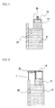
- FIG. 5 is a sectional view showing a relevant part of the stator of Embodiment 1 of the present invention and shows the joint state of the terminal wires.
- the terminal wire 19 on the inner circumferential side and the terminal wire 20 on the outer circumferential side of each slot as shown in FIG.
- the terminal wire 19 is firstly bent to the outer circumferential side above the coil end 21; the end of the terminal wire 19 is secondarily bent so as to be oriented in the axial direction of the stator; the side surface of the terminal wire 19 is brought into contact with the side surface of the terminal wire 20 to form a joint part above the coil end 21; and the terminal wires 19, 20 are positioned so as to be the same height between the end surfaces of the respective terminal wires over substantially the whole circumference of the stator 5. Then, the joint parts of the terminal wires 19, 20 whose side surfaces are thus brought into contact with each other are connected over substantially the whole circumference of the stator 5.
- the connection is performed by, for example, tungsten inert gas (TIG) welding.
- connection terminals which are provided with connection terminals above the coil end 21 and whose terminal parts are not bent. Then, such a coil 16 is joined via the connection terminals.
- the terminal parts to be joined to the connection terminals are oriented in the axial direction. As described above, when the connection terminals are used in the case of joining the terminal wires, bending work of the terminal wires of the connection terminal parts can be omitted.
- all coil terminals are oriented in the axial direction at substantially the same height; and therefore, all film peeled-off parts can be insulated in one process by fluidization dip. Then, insulation material can be avoided from being applied to a place other than a place where an insulation part is needed.
- FIG. 6 is a sectional view showing a relevant part of a stator according to Embodiment 2 of the present invention, and the stator of Embodiment 2 is different in a method of bending a terminal wire 19 and a terminal wire 20, as compared to Embodiment 1. More specifically, in the stator of Embodiment 2, as for the terminal wire 19 on the inner circumferential side and the terminal wire 20 on the outer circumferential side of the coil 16 arranged in each slot 14, as shown in FIG.
- the terminal wire 20 is firstly bent to the inner circumferential side above a coil end 21; the end of the terminal wire 20 is secondarily bent so as to be oriented in the axial direction of the stator; the side surface of the terminal wire 19 is brought into contact with the side surface of the terminal wire 20 to form a joint part above the coil end 21; and the terminal wires 19, 20 are positioned so as to be the same height between the end surfaces of the respective terminal wires over substantially the whole circumference of the stator 5. Then, the joint parts of the terminal wires 19, 20 whose side surfaces are thus brought into contact with each other are connected over substantially the whole circumference of the stator 5 by, for example, TIG welding.
- FIG. 7 is a sectional view showing a relevant part of a stator according to Embodiment 3 of the present invention, and the stator of Embodiment 3 is different in a method of bending a terminal wire 19 and a terminal wire 20, as compared to Embodiments 1, 2. More specifically, in the stator of Embodiment 3, as for the terminal wire 19 on the inner circumferential side and the terminal wire 20 on the outer circumferential side of the coil 16 arranged in each slot, as shown in FIG. 7 , the terminal wire 19 is firstly bent to the outer circumferential side above a coil end 21; and the end of the terminal wire 19 is secondarily bent so as to be oriented in the axial direction of the stator.
- the terminal wire 20 on the outer circumferential side is also firstly bent to the inner circumferential side above the coil end 21; the end of the terminal wire 20 is secondarily bent so as to be oriented in the axial direction of the stator; the side surface of the terminal wire 19 is brought into contact with the side surface of the terminal wire 20 to form a joint part above the coil end 21; and the terminal wires 19, 20 are positioned so as to be the same height between the end surfaces of the respective terminal wires over substantially the whole circumference of the stator 5. Then, the joint parts of the terminal wires 19, 20 whose side surfaces are thus brought into contact with each other are connected by, for example, TIG welding over substantially the whole circumference of the stator 5.
- Embodiment 3 bending at a close distance is applied to both end coils, whereby rigidity of the stator is enhanced and seismic adequacy can be improved, in addition to the same effects as Embodiment 1.
- the present invention is useful as a stator of a rotating electrical machine to be mounted in a vehicle such as an EV and an HEV and to be required to provide a small size and a high output.
Landscapes
- Engineering & Computer Science (AREA)
- Power Engineering (AREA)
- Manufacture Of Motors, Generators (AREA)
- Windings For Motors And Generators (AREA)
- Iron Core Of Rotating Electric Machines (AREA)
- Insulation, Fastening Of Motor, Generator Windings (AREA)
Applications Claiming Priority (1)
| Application Number | Priority Date | Filing Date | Title |
|---|---|---|---|
| PCT/JP2013/075137 WO2015040692A1 (fr) | 2013-09-18 | 2013-09-18 | Stator de machine électrique rotative |
Publications (3)
| Publication Number | Publication Date |
|---|---|
| EP3048704A1 true EP3048704A1 (fr) | 2016-07-27 |
| EP3048704A4 EP3048704A4 (fr) | 2017-06-14 |
| EP3048704B1 EP3048704B1 (fr) | 2022-01-12 |
Family
ID=52688378
Family Applications (1)
| Application Number | Title | Priority Date | Filing Date |
|---|---|---|---|
| EP13893881.6A Not-in-force EP3048704B1 (fr) | 2013-09-18 | 2013-09-18 | Stator de machine électrique rotative |
Country Status (5)
| Country | Link |
|---|---|
| US (1) | US10396614B2 (fr) |
| EP (1) | EP3048704B1 (fr) |
| JP (1) | JP6080964B2 (fr) |
| CN (1) | CN105556803B (fr) |
| WO (1) | WO2015040692A1 (fr) |
Families Citing this family (3)
| Publication number | Priority date | Publication date | Assignee | Title |
|---|---|---|---|---|
| JP6364465B2 (ja) * | 2016-12-09 | 2018-07-25 | 本田技研工業株式会社 | スロットコイル及び回転電機のステータ |
| CN108667245B (zh) * | 2018-05-16 | 2024-04-02 | 成都华川电装有限责任公司 | 扁线定子焊接端并线平头机构 |
| US11791673B2 (en) * | 2019-10-11 | 2023-10-17 | Steering Solutions Ip Holding Corporation | Stator routing system |
Family Cites Families (36)
| Publication number | Priority date | Publication date | Assignee | Title |
|---|---|---|---|---|
| JP3407643B2 (ja) | 1997-05-26 | 2003-05-19 | 株式会社デンソー | 車両用交流発電機 |
| BR9801695B1 (pt) | 1997-05-26 | 2009-08-11 | máquina elétrica rotativa. | |
| DE69830869T2 (de) | 1997-05-26 | 2006-05-24 | Denso Corp., Kariya | Wechselstromgenerator für Kraftfahrzeuge |
| US6137201A (en) | 1997-05-26 | 2000-10-24 | Denso Corporation | AC generator for vehicles |
| CN1200591A (zh) | 1997-05-26 | 1998-12-02 | 株式会社电装 | 车用发电机 |
| US5952749A (en) | 1997-05-26 | 1999-09-14 | Denso Corporation | Cooling arrangement of alternator |
| US5965965A (en) | 1997-05-26 | 1999-10-12 | Denso Corporation | Stator winding arrangement of alternator for vehicle |
| WO1998054822A1 (fr) | 1997-05-26 | 1998-12-03 | Denso Corporation | Alternateur pour vehicule |
| EP1237254B1 (fr) | 1997-05-26 | 2008-06-04 | Denso Corporation | Alternateur pour véhicules automobiles |
| EP0881756B1 (fr) | 1997-05-26 | 2001-08-01 | Denso Corporation | Alternateur de véhicule automobile |
| US6124660A (en) | 1997-05-26 | 2000-09-26 | Denso Corporation | AC generator for vehicles |
| CA2238504C (fr) | 1997-05-26 | 2001-03-13 | Atsushi Umeda | Agencement du stator d'un alternateur pour vehicule |
| US5986375A (en) | 1997-09-26 | 1999-11-16 | Denso Corporation | Alternator for vehicle |
| EP0910155B1 (fr) | 1997-09-26 | 2001-08-29 | Denso Corporation | Alternateur de véhicule automobile |
| DE69804284T3 (de) | 1997-09-26 | 2009-07-23 | DENSO CORPORATION, Kariya-shi | Fahrzeugsgenerator |
| JP3769990B2 (ja) | 1999-08-06 | 2006-04-26 | 株式会社デンソー | 導体セグメント接合型の回転電機及びその製造方法 |
| US6181043B1 (en) * | 1997-12-10 | 2001-01-30 | Denso Corporation | Alternator for vehicle |
| JP4461590B2 (ja) * | 2000-08-25 | 2010-05-12 | 株式会社デンソー | 車両用交流発電機 |
| JP3740421B2 (ja) * | 2002-01-10 | 2006-02-01 | 株式会社日立製作所 | 回転電機と固定子導線の接続方法 |
| FR2868620B1 (fr) * | 2004-03-31 | 2006-07-21 | Valeo Equip Electr Moteur | Induit polyphase pour machine electrique tournante, notamment un alternateur pour vehicule automobile, et son procede de fabrication |
| US7291954B2 (en) * | 2004-04-28 | 2007-11-06 | Mitsubishi Denki Kabushiki Kaisha | Dynamoelectric machine |
| JP2006187164A (ja) * | 2004-12-28 | 2006-07-13 | Denso Corp | 回転電機 |
| JP4497008B2 (ja) * | 2005-03-30 | 2010-07-07 | 株式会社デンソー | 車両用回転電機の固定子 |
| JP4662141B2 (ja) * | 2005-07-28 | 2011-03-30 | 株式会社デンソー | 固定子を含む回転電機 |
| JP2009011116A (ja) * | 2007-06-29 | 2009-01-15 | Hitachi Ltd | 渡り導体部がクランク形状の波巻きコイルを備えた回転電機、分布巻固定子並びにそれらの成形方法及び成形装置 |
| JP4301334B2 (ja) * | 2007-10-19 | 2009-07-22 | トヨタ自動車株式会社 | 回転電機 |
| JP5237048B2 (ja) * | 2008-02-13 | 2013-07-17 | 日立オートモティブシステムズ株式会社 | 回転電機、および固定子巻線 |
| JP5586969B2 (ja) | 2010-01-21 | 2014-09-10 | 株式会社デンソー | 回転電機の固定子 |
| JPWO2011102150A1 (ja) * | 2010-02-18 | 2013-06-17 | アイシン・エィ・ダブリュ株式会社 | 回転電機用電機子 |
| JP5704394B2 (ja) * | 2010-03-31 | 2015-04-22 | 株式会社デンソー | 回転電機の固定子 |
| JP5573327B2 (ja) * | 2010-04-21 | 2014-08-20 | 株式会社デンソー | 回転電機の固定子及びその製造方法 |
| JP5353874B2 (ja) * | 2010-12-28 | 2013-11-27 | 株式会社デンソー | 回転電機の固定子及びその製造方法 |
| JP2012143068A (ja) | 2010-12-28 | 2012-07-26 | Denso Corp | 回転電機の固定子及びその製造方法 |
| JP2012139075A (ja) | 2010-12-28 | 2012-07-19 | Hitachi Automotive Systems Ltd | 回転電機 |
| WO2014034157A1 (fr) * | 2012-08-31 | 2014-03-06 | 三菱電機株式会社 | Machine électrique rotative et son procédé de fabrication |
| JP5839295B2 (ja) * | 2013-09-04 | 2016-01-06 | 株式会社デンソー | 回転電機の固定子 |
-
2013
- 2013-09-18 JP JP2015537464A patent/JP6080964B2/ja active Active
- 2013-09-18 US US14/900,395 patent/US10396614B2/en active Active
- 2013-09-18 WO PCT/JP2013/075137 patent/WO2015040692A1/fr not_active Ceased
- 2013-09-18 EP EP13893881.6A patent/EP3048704B1/fr not_active Not-in-force
- 2013-09-18 CN CN201380079646.7A patent/CN105556803B/zh active Active
Also Published As
| Publication number | Publication date |
|---|---|
| CN105556803A (zh) | 2016-05-04 |
| CN105556803B (zh) | 2019-03-05 |
| EP3048704A4 (fr) | 2017-06-14 |
| EP3048704B1 (fr) | 2022-01-12 |
| US20160149456A1 (en) | 2016-05-26 |
| US10396614B2 (en) | 2019-08-27 |
| JP6080964B2 (ja) | 2017-02-15 |
| JPWO2015040692A1 (ja) | 2017-03-02 |
| WO2015040692A1 (fr) | 2015-03-26 |
Similar Documents
| Publication | Publication Date | Title |
|---|---|---|
| US11616407B2 (en) | Segment-core coupled body and method of manufacturing armature | |
| US7598637B2 (en) | Stator for an electrical machine | |
| JP5306411B2 (ja) | 回転電機 | |
| US9331539B2 (en) | Motor power distribution apparatus | |
| US8497618B2 (en) | Stator for rotatry electrical machine including an insulating bobbin | |
| US7948130B2 (en) | Rotating electrical machine | |
| EP2639933B1 (fr) | Machine dynamoélectrique | |
| JP5140389B2 (ja) | 回転電機用の固定子、及びこれを用いた回転電機 | |
| CN101728887B (zh) | 用于电机线圈的配线部件 | |
| US20150097453A1 (en) | Rotary electric machine | |
| CN109075668B (zh) | 电枢的制造方法、旋转电机的制造方法、电枢、旋转电机及电枢的制造装置 | |
| US20070205679A1 (en) | Brushless Motor | |
| EP3176912A1 (fr) | Stator et machine tournante | |
| JP4486678B2 (ja) | 回転電動機の電機子、回転電動機及びその製造方法 | |
| US10903709B2 (en) | Armature of electric motor | |
| CN113454880B (zh) | 旋转电机的定子、旋转电机、旋转电机的定子的制造方法及旋转电机的制造方法 | |
| US20180175570A1 (en) | Bus bar unit and rotary electric machine having the same | |
| JP2012143064A (ja) | 回転電機の固定子及びその製造方法 | |
| JP2016052224A (ja) | ステータ、そのステータを適用した回転電機及びステータの結線方法 | |
| CN110474461A (zh) | 马达的定子及其制造方法 | |
| US11050317B2 (en) | Rotary electric machine and manufacturing method thereof | |
| CN108028558B (zh) | 旋转电机以及旋转电机的制造方法 | |
| EP3048704B1 (fr) | Stator de machine électrique rotative | |
| JP7107663B2 (ja) | 回転電機のステータ | |
| CN106487142A (zh) | 旋转电机的接线单元 |
Legal Events
| Date | Code | Title | Description |
|---|---|---|---|
| PUAI | Public reference made under article 153(3) epc to a published international application that has entered the european phase |
Free format text: ORIGINAL CODE: 0009012 |
|
| 17P | Request for examination filed |
Effective date: 20151214 |
|
| AK | Designated contracting states |
Kind code of ref document: A1 Designated state(s): AL AT BE BG CH CY CZ DE DK EE ES FI FR GB GR HR HU IE IS IT LI LT LU LV MC MK MT NL NO PL PT RO RS SE SI SK SM TR |
|
| AX | Request for extension of the european patent |
Extension state: BA ME |
|
| DAX | Request for extension of the european patent (deleted) | ||
| A4 | Supplementary search report drawn up and despatched |
Effective date: 20170517 |
|
| RIC1 | Information provided on ipc code assigned before grant |
Ipc: H02K 3/04 20060101AFI20170511BHEP Ipc: H02K 3/50 20060101ALI20170511BHEP Ipc: H02K 3/28 20060101ALI20170511BHEP Ipc: H02K 3/12 20060101ALI20170511BHEP |
|
| STAA | Information on the status of an ep patent application or granted ep patent |
Free format text: STATUS: EXAMINATION IS IN PROGRESS |
|
| 17Q | First examination report despatched |
Effective date: 20190424 |
|
| GRAP | Despatch of communication of intention to grant a patent |
Free format text: ORIGINAL CODE: EPIDOSNIGR1 |
|
| STAA | Information on the status of an ep patent application or granted ep patent |
Free format text: STATUS: GRANT OF PATENT IS INTENDED |
|
| INTG | Intention to grant announced |
Effective date: 20211022 |
|
| GRAS | Grant fee paid |
Free format text: ORIGINAL CODE: EPIDOSNIGR3 |
|
| GRAA | (expected) grant |
Free format text: ORIGINAL CODE: 0009210 |
|
| STAA | Information on the status of an ep patent application or granted ep patent |
Free format text: STATUS: THE PATENT HAS BEEN GRANTED |
|
| AK | Designated contracting states |
Kind code of ref document: B1 Designated state(s): AL AT BE BG CH CY CZ DE DK EE ES FI FR GB GR HR HU IE IS IT LI LT LU LV MC MK MT NL NO PL PT RO RS SE SI SK SM TR |
|
| REG | Reference to a national code |
Ref country code: GB Ref legal event code: FG4D |
|
| REG | Reference to a national code |
Ref country code: CH Ref legal event code: EP |
|
| REG | Reference to a national code |
Ref country code: DE Ref legal event code: R096 Ref document number: 602013080702 Country of ref document: DE |
|
| REG | Reference to a national code |
Ref country code: IE Ref legal event code: FG4D |
|
| REG | Reference to a national code |
Ref country code: AT Ref legal event code: REF Ref document number: 1463026 Country of ref document: AT Kind code of ref document: T Effective date: 20220215 |
|
| REG | Reference to a national code |
Ref country code: LT Ref legal event code: MG9D |
|
| REG | Reference to a national code |
Ref country code: NL Ref legal event code: MP Effective date: 20220112 |
|
| REG | Reference to a national code |
Ref country code: AT Ref legal event code: MK05 Ref document number: 1463026 Country of ref document: AT Kind code of ref document: T Effective date: 20220112 |
|
| PG25 | Lapsed in a contracting state [announced via postgrant information from national office to epo] |
Ref country code: NL Free format text: LAPSE BECAUSE OF FAILURE TO SUBMIT A TRANSLATION OF THE DESCRIPTION OR TO PAY THE FEE WITHIN THE PRESCRIBED TIME-LIMIT Effective date: 20220112 |
|
| PG25 | Lapsed in a contracting state [announced via postgrant information from national office to epo] |
Ref country code: SE Free format text: LAPSE BECAUSE OF FAILURE TO SUBMIT A TRANSLATION OF THE DESCRIPTION OR TO PAY THE FEE WITHIN THE PRESCRIBED TIME-LIMIT Effective date: 20220112 Ref country code: RS Free format text: LAPSE BECAUSE OF FAILURE TO SUBMIT A TRANSLATION OF THE DESCRIPTION OR TO PAY THE FEE WITHIN THE PRESCRIBED TIME-LIMIT Effective date: 20220112 Ref country code: PT Free format text: LAPSE BECAUSE OF FAILURE TO SUBMIT A TRANSLATION OF THE DESCRIPTION OR TO PAY THE FEE WITHIN THE PRESCRIBED TIME-LIMIT Effective date: 20220512 Ref country code: NO Free format text: LAPSE BECAUSE OF FAILURE TO SUBMIT A TRANSLATION OF THE DESCRIPTION OR TO PAY THE FEE WITHIN THE PRESCRIBED TIME-LIMIT Effective date: 20220412 Ref country code: LT Free format text: LAPSE BECAUSE OF FAILURE TO SUBMIT A TRANSLATION OF THE DESCRIPTION OR TO PAY THE FEE WITHIN THE PRESCRIBED TIME-LIMIT Effective date: 20220112 Ref country code: HR Free format text: LAPSE BECAUSE OF FAILURE TO SUBMIT A TRANSLATION OF THE DESCRIPTION OR TO PAY THE FEE WITHIN THE PRESCRIBED TIME-LIMIT Effective date: 20220112 Ref country code: ES Free format text: LAPSE BECAUSE OF FAILURE TO SUBMIT A TRANSLATION OF THE DESCRIPTION OR TO PAY THE FEE WITHIN THE PRESCRIBED TIME-LIMIT Effective date: 20220112 Ref country code: BG Free format text: LAPSE BECAUSE OF FAILURE TO SUBMIT A TRANSLATION OF THE DESCRIPTION OR TO PAY THE FEE WITHIN THE PRESCRIBED TIME-LIMIT Effective date: 20220412 |
|
| PG25 | Lapsed in a contracting state [announced via postgrant information from national office to epo] |
Ref country code: PL Free format text: LAPSE BECAUSE OF FAILURE TO SUBMIT A TRANSLATION OF THE DESCRIPTION OR TO PAY THE FEE WITHIN THE PRESCRIBED TIME-LIMIT Effective date: 20220112 Ref country code: LV Free format text: LAPSE BECAUSE OF FAILURE TO SUBMIT A TRANSLATION OF THE DESCRIPTION OR TO PAY THE FEE WITHIN THE PRESCRIBED TIME-LIMIT Effective date: 20220112 Ref country code: GR Free format text: LAPSE BECAUSE OF FAILURE TO SUBMIT A TRANSLATION OF THE DESCRIPTION OR TO PAY THE FEE WITHIN THE PRESCRIBED TIME-LIMIT Effective date: 20220413 Ref country code: FI Free format text: LAPSE BECAUSE OF FAILURE TO SUBMIT A TRANSLATION OF THE DESCRIPTION OR TO PAY THE FEE WITHIN THE PRESCRIBED TIME-LIMIT Effective date: 20220112 Ref country code: AT Free format text: LAPSE BECAUSE OF FAILURE TO SUBMIT A TRANSLATION OF THE DESCRIPTION OR TO PAY THE FEE WITHIN THE PRESCRIBED TIME-LIMIT Effective date: 20220112 |
|
| PG25 | Lapsed in a contracting state [announced via postgrant information from national office to epo] |
Ref country code: IS Free format text: LAPSE BECAUSE OF FAILURE TO SUBMIT A TRANSLATION OF THE DESCRIPTION OR TO PAY THE FEE WITHIN THE PRESCRIBED TIME-LIMIT Effective date: 20220512 |
|
| REG | Reference to a national code |
Ref country code: DE Ref legal event code: R097 Ref document number: 602013080702 Country of ref document: DE |
|
| PG25 | Lapsed in a contracting state [announced via postgrant information from national office to epo] |
Ref country code: SM Free format text: LAPSE BECAUSE OF FAILURE TO SUBMIT A TRANSLATION OF THE DESCRIPTION OR TO PAY THE FEE WITHIN THE PRESCRIBED TIME-LIMIT Effective date: 20220112 Ref country code: SK Free format text: LAPSE BECAUSE OF FAILURE TO SUBMIT A TRANSLATION OF THE DESCRIPTION OR TO PAY THE FEE WITHIN THE PRESCRIBED TIME-LIMIT Effective date: 20220112 Ref country code: RO Free format text: LAPSE BECAUSE OF FAILURE TO SUBMIT A TRANSLATION OF THE DESCRIPTION OR TO PAY THE FEE WITHIN THE PRESCRIBED TIME-LIMIT Effective date: 20220112 Ref country code: EE Free format text: LAPSE BECAUSE OF FAILURE TO SUBMIT A TRANSLATION OF THE DESCRIPTION OR TO PAY THE FEE WITHIN THE PRESCRIBED TIME-LIMIT Effective date: 20220112 Ref country code: DK Free format text: LAPSE BECAUSE OF FAILURE TO SUBMIT A TRANSLATION OF THE DESCRIPTION OR TO PAY THE FEE WITHIN THE PRESCRIBED TIME-LIMIT Effective date: 20220112 Ref country code: CZ Free format text: LAPSE BECAUSE OF FAILURE TO SUBMIT A TRANSLATION OF THE DESCRIPTION OR TO PAY THE FEE WITHIN THE PRESCRIBED TIME-LIMIT Effective date: 20220112 |
|
| PLBE | No opposition filed within time limit |
Free format text: ORIGINAL CODE: 0009261 |
|
| STAA | Information on the status of an ep patent application or granted ep patent |
Free format text: STATUS: NO OPPOSITION FILED WITHIN TIME LIMIT |
|
| PG25 | Lapsed in a contracting state [announced via postgrant information from national office to epo] |
Ref country code: AL Free format text: LAPSE BECAUSE OF FAILURE TO SUBMIT A TRANSLATION OF THE DESCRIPTION OR TO PAY THE FEE WITHIN THE PRESCRIBED TIME-LIMIT Effective date: 20220112 |
|
| 26N | No opposition filed |
Effective date: 20221013 |
|
| PG25 | Lapsed in a contracting state [announced via postgrant information from national office to epo] |
Ref country code: SI Free format text: LAPSE BECAUSE OF FAILURE TO SUBMIT A TRANSLATION OF THE DESCRIPTION OR TO PAY THE FEE WITHIN THE PRESCRIBED TIME-LIMIT Effective date: 20220112 |
|
| REG | Reference to a national code |
Ref country code: DE Ref legal event code: R119 Ref document number: 602013080702 Country of ref document: DE |
|
| PG25 | Lapsed in a contracting state [announced via postgrant information from national office to epo] |
Ref country code: MC Free format text: LAPSE BECAUSE OF FAILURE TO SUBMIT A TRANSLATION OF THE DESCRIPTION OR TO PAY THE FEE WITHIN THE PRESCRIBED TIME-LIMIT Effective date: 20220112 |
|
| REG | Reference to a national code |
Ref country code: CH Ref legal event code: PL |
|
| GBPC | Gb: european patent ceased through non-payment of renewal fee |
Effective date: 20220918 |
|
| REG | Reference to a national code |
Ref country code: BE Ref legal event code: MM Effective date: 20220930 |
|
| P01 | Opt-out of the competence of the unified patent court (upc) registered |
Effective date: 20230512 |
|
| PG25 | Lapsed in a contracting state [announced via postgrant information from national office to epo] |
Ref country code: LU Free format text: LAPSE BECAUSE OF NON-PAYMENT OF DUE FEES Effective date: 20220918 |
|
| PG25 | Lapsed in a contracting state [announced via postgrant information from national office to epo] |
Ref country code: LI Free format text: LAPSE BECAUSE OF NON-PAYMENT OF DUE FEES Effective date: 20220930 Ref country code: IT Free format text: LAPSE BECAUSE OF FAILURE TO SUBMIT A TRANSLATION OF THE DESCRIPTION OR TO PAY THE FEE WITHIN THE PRESCRIBED TIME-LIMIT Effective date: 20220112 Ref country code: IE Free format text: LAPSE BECAUSE OF NON-PAYMENT OF DUE FEES Effective date: 20220918 Ref country code: DE Free format text: LAPSE BECAUSE OF NON-PAYMENT OF DUE FEES Effective date: 20230401 Ref country code: CH Free format text: LAPSE BECAUSE OF NON-PAYMENT OF DUE FEES Effective date: 20220930 |
|
| PG25 | Lapsed in a contracting state [announced via postgrant information from national office to epo] |
Ref country code: BE Free format text: LAPSE BECAUSE OF NON-PAYMENT OF DUE FEES Effective date: 20220930 |
|
| PG25 | Lapsed in a contracting state [announced via postgrant information from national office to epo] |
Ref country code: GB Free format text: LAPSE BECAUSE OF NON-PAYMENT OF DUE FEES Effective date: 20220918 |
|
| PGFP | Annual fee paid to national office [announced via postgrant information from national office to epo] |
Ref country code: FR Payment date: 20230808 Year of fee payment: 11 |
|
| PG25 | Lapsed in a contracting state [announced via postgrant information from national office to epo] |
Ref country code: HU Free format text: LAPSE BECAUSE OF FAILURE TO SUBMIT A TRANSLATION OF THE DESCRIPTION OR TO PAY THE FEE WITHIN THE PRESCRIBED TIME-LIMIT; INVALID AB INITIO Effective date: 20130918 |
|
| PG25 | Lapsed in a contracting state [announced via postgrant information from national office to epo] |
Ref country code: CY Free format text: LAPSE BECAUSE OF FAILURE TO SUBMIT A TRANSLATION OF THE DESCRIPTION OR TO PAY THE FEE WITHIN THE PRESCRIBED TIME-LIMIT Effective date: 20220112 |
|
| PG25 | Lapsed in a contracting state [announced via postgrant information from national office to epo] |
Ref country code: MK Free format text: LAPSE BECAUSE OF FAILURE TO SUBMIT A TRANSLATION OF THE DESCRIPTION OR TO PAY THE FEE WITHIN THE PRESCRIBED TIME-LIMIT Effective date: 20220112 |
|
| PG25 | Lapsed in a contracting state [announced via postgrant information from national office to epo] |
Ref country code: MT Free format text: LAPSE BECAUSE OF FAILURE TO SUBMIT A TRANSLATION OF THE DESCRIPTION OR TO PAY THE FEE WITHIN THE PRESCRIBED TIME-LIMIT Effective date: 20220112 |
|
| PG25 | Lapsed in a contracting state [announced via postgrant information from national office to epo] |
Ref country code: FR Free format text: LAPSE BECAUSE OF NON-PAYMENT OF DUE FEES Effective date: 20240930 |
|
| PG25 | Lapsed in a contracting state [announced via postgrant information from national office to epo] |
Ref country code: TR Free format text: LAPSE BECAUSE OF FAILURE TO SUBMIT A TRANSLATION OF THE DESCRIPTION OR TO PAY THE FEE WITHIN THE PRESCRIBED TIME-LIMIT Effective date: 20220112 |