EP3050657B1 - Appareil automatisé de traitement de matière ligneuse faite de panneaux - Google Patents
Appareil automatisé de traitement de matière ligneuse faite de panneaux Download PDFInfo
- Publication number
- EP3050657B1 EP3050657B1 EP16153645.3A EP16153645A EP3050657B1 EP 3050657 B1 EP3050657 B1 EP 3050657B1 EP 16153645 A EP16153645 A EP 16153645A EP 3050657 B1 EP3050657 B1 EP 3050657B1
- Authority
- EP
- European Patent Office
- Prior art keywords
- panel
- work table
- edging
- cutting
- panels
- Prior art date
- Legal status (The legal status is an assumption and is not a legal conclusion. Google has not performed a legal analysis and makes no representation as to the accuracy of the status listed.)
- Active
Links
Images




Classifications
-
- B—PERFORMING OPERATIONS; TRANSPORTING
- B27—WORKING OR PRESERVING WOOD OR SIMILAR MATERIAL; NAILING OR STAPLING MACHINES IN GENERAL
- B27C—PLANING, DRILLING, MILLING, TURNING OR UNIVERSAL MACHINES FOR WOOD OR SIMILAR MATERIAL
- B27C9/00—Multi-purpose machines; Universal machines; Equipment therefor
- B27C9/04—Multi-purpose machines; Universal machines; Equipment therefor with a plurality of working spindles
-
- B—PERFORMING OPERATIONS; TRANSPORTING
- B23—MACHINE TOOLS; METAL-WORKING NOT OTHERWISE PROVIDED FOR
- B23D—PLANING; SLOTTING; SHEARING; BROACHING; SAWING; FILING; SCRAPING; LIKE OPERATIONS FOR WORKING METAL BY REMOVING MATERIAL, NOT OTHERWISE PROVIDED FOR
- B23D47/00—Sawing machines or sawing devices working with circular saw blades, characterised only by constructional features of particular parts
- B23D47/04—Sawing machines or sawing devices working with circular saw blades, characterised only by constructional features of particular parts of devices for feeding, positioning, clamping, or rotating work
-
- B—PERFORMING OPERATIONS; TRANSPORTING
- B27—WORKING OR PRESERVING WOOD OR SIMILAR MATERIAL; NAILING OR STAPLING MACHINES IN GENERAL
- B27B—SAWS FOR WOOD OR SIMILAR MATERIAL; COMPONENTS OR ACCESSORIES THEREFOR
- B27B27/00—Guide fences or stops for timber in saw mills or sawing machines; Measuring equipment thereon
- B27B27/04—Guide fences or stops for timber in saw mills or sawing machines; Measuring equipment thereon arranged perpendicularly to the plane of the saw blade
-
- B—PERFORMING OPERATIONS; TRANSPORTING
- B27—WORKING OR PRESERVING WOOD OR SIMILAR MATERIAL; NAILING OR STAPLING MACHINES IN GENERAL
- B27B—SAWS FOR WOOD OR SIMILAR MATERIAL; COMPONENTS OR ACCESSORIES THEREFOR
- B27B5/00—Sawing machines working with circular or cylindrical saw blades; Components or equipment therefor
- B27B5/02—Sawing machines working with circular or cylindrical saw blades; Components or equipment therefor characterised by a special purpose only
- B27B5/06—Sawing machines working with circular or cylindrical saw blades; Components or equipment therefor characterised by a special purpose only for dividing plates in parts of determined size, e.g. panels
-
- B—PERFORMING OPERATIONS; TRANSPORTING
- B27—WORKING OR PRESERVING WOOD OR SIMILAR MATERIAL; NAILING OR STAPLING MACHINES IN GENERAL
- B27D—WORKING VENEER OR PLYWOOD
- B27D5/00—Other working of veneer or plywood specially adapted to veneer or plywood
- B27D5/003—Other working of veneer or plywood specially adapted to veneer or plywood securing a veneer strip to a panel edge
-
- B—PERFORMING OPERATIONS; TRANSPORTING
- B27—WORKING OR PRESERVING WOOD OR SIMILAR MATERIAL; NAILING OR STAPLING MACHINES IN GENERAL
- B27M—WORKING OF WOOD NOT PROVIDED FOR IN SUBCLASSES B27B - B27L; MANUFACTURE OF SPECIFIC WOODEN ARTICLES
- B27M1/00—Working of wood not provided for in subclasses B27B - B27L, e.g. by stretching
- B27M1/08—Working of wood not provided for in subclasses B27B - B27L, e.g. by stretching by multi-step processes
Definitions
- Another object of the invention is to provide an automated apparatus that can be installed in a relatively contained area.
- Another object of the invention is to provide an automated apparatus that is capable of machining a plurality of panels simultaneously.
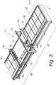
- the means 12 for loading blank panels on the cutting machine 11 are constituted by a Cartesian manipulator 25 on a portal 26, the vertical arm 27 of which supports a sucker-carrying frame 28 by way of a rotoidal joint 29.
- a machine 11 for the longitudinal and transverse cutting to size of a blank panel is also the subject matter of the present invention.
- the work table 32 is constituted by a plurality of mutually adjacent sliding panels 37.
- Each sliding panel 37 is constituted by elastically deformable bristles 38, as shown for the purposes of example in Figure 6 .
- the first means 33 are arranged in a first region 50 of the work table 32, which is in front of the cutting means 36, and are designed to push the loaded panel 35 toward the cutting means 36 and to follow it in the same advancement direction during processing;
- the second means 34 are arranged in a second region 51 of the work table 32, which is to the rear of the cutting means 36, and are designed to entrain the loaded panel 35 away from the cutting means 36 and to accompany it in the same advancement direction during the processing, in order to carry it, once cutting has been completed, to an unloading region 51a, available for pick-up by the means 23 and 24 for transferring the cut panels to the edging centers 13 and 14.
- the means 45 and 46 for moving the grip clamps 43 and 44 are constituted, in the present embodiment, by a motorized belt 47, visible in Figures 5 , 6 and 7 , and a transport flange 48 for each clamp 43 and 44, with the clamps 43 and 44 being fixed to the corresponding transport flange.
- Each flange 48 carries reversible means of coupling to the motorized belt 47, constituted for example by a clamp 52 gripping the motorized belt 47 proper and mounted on the flange 48 and the jaws 53 and 54 of which can be seen in Figure 6 .
- a flange, or a plurality of flanges, at the choice of the designer, is or are coupled to the motorized belt, and the motorized belt 47 is actuated so as to move the clamps carried by the coupled flanges to a new grip position, according to the technical requirements of the moment.
- the gripping clamp 52 is actuated during opening and closure of its jaws 53 and 54 by a pneumatic linear actuator, not shown, which can be of conventional type.
- the reference numeral 55 designates means of sliding on a guide, which are associated with each flange 48; such means 55 of sliding on a guide comprise a slider 67 which is arranged to slide on a guide bar 68 and means 69 of locking the slider to the guide bar, in order to stabilize the position of the clamp 43 with respect to the sliding portal 39 that carries it.
- Each grip clamp for example a grip clamp 43 as shown in Figure 6 , comprises:
- the means for moving the first jaw 56 are constituted by a pneumatic linear actuator 59, fixed to the flange 48.
- the stem of the pneumatic linear actuator 59 supports a plate 60 which extends in a cantilever fashion from the stem in order to support a bar 61 which in turn supports, at the lower end, the first jaw 56.
- a first guide 62 for a translating slider 63 fixed to the pneumatic linear actuator 59 and a second guide 64 for a second translating slider 65 fixed to the presser body that defines the second jaw 57.
- the means for moving the second jaw 57 are constituted by a further pneumatic linear actuator 66 the stem of which is fixed to the plate 60 and the body of which is the presser body that defines the second jaw 57.
- the second translating slider 65 is thus associated with the means for moving the second jaw 57.
- the clamp 43 In order to grip an edge 58 of the panel 35 the clamp 43 is positioned proximate to the edge 58, and then the first jaw 56 is pushed downwardly to compress the bristles 38 until they descend fully below the edge 58.
- the clamp 43 is then made to advance by way of a movement of the sliding portal 39 in the direction X, so that the first jaw 56 is arranged below the edge 58.
- first jaw 56 is raised until it touches the edge 58 without lifting it, and at the same time the second jaw 57 is lowered in order to determine the gripping of the edge 58 while keeping the panel 35 resting on the bristles 38 of the sliding panels 37.
- the sliding portal 39 is moved toward the cutting means 36; the bristles 38, which are elastically deformable, bend at the passage of the first jaw 56 which is immersed in them, and then return to the original, substantially vertical position when the first jaw is moved away.
- the cutting means 36 are constituted by a vertical axis mill 70, mounted on a motorized slide 71 adapted to slide on two supporting guides 72, the motorized slide 71 and supporting guides 72 defining the means for movement of the cutting means in a direction Y which is transverse to the direction X of advancement of the loaded panels.
- Operation of the cutting machine 11 is the following.
- the panel 35 is gripped by the clamps 44 of the second sliding portal 40, following the machining thereof together with the first sliding portal 39.
- the finished piece is released from the clamps 44 of the second portal 40 on an unloading region of the work table 32, available to be picked up by the means 23 and 24 for transferring the cut panels to the edging centers, 13 and 14.
- the cutting machine 11 comprises a lateral conveyor belt 73 for unloading the shavings, an upper aspiration device 74, as in Figure 3 , arranged so as to operate above the panel being processed, supported by a fixed portal 75, and a lower aspiration device 76, integral with the electric spindle of the cutting means 36, as in Figure 4 .
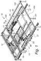
- the work tables 17, 18, 19 and 20 are divided into first work tables 17 and 19 and second work tables 18 and 20, as in Figure 1 .
- the first work table 17 is constituted by a series of profiles 80 arranged side-by-side, which between them define channels 81 for the sliding of panel-gripping clamps 82.
- the panel-gripping clamps 82 are carried by a crossmember 83, motorized, which is adapted to carry translationally the clamps 83 in the channels 81, toward or away from the panel being processed.
- the first work table also comprises retractable abutment protrusions 84 which are adapted to push the panel to be processed against the clamps in order to ensure the precision of the gripping of the latter.
- the retractable abutment protrusions 84 are supported by means for their retractable movement, below the resting surface of the panels.
- the clamps 83 are also carried by means that enable their movement up and down, so as to also be able to translate below the resting surface, leaving the latter free to receive a new panel to be processed, with consequent speeding up of the loading times.
- the clamps 83 push and carry the panel to be processed toward the processing side 86 of the first work table 17, i.e. the side where the edging means 21 operate.
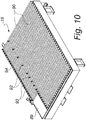
- a second work table 18, shown for the purposes of example in Figures 10 and 11 is dedicated to the support of the semi-finished pieces for the edging of the short sides.
- the second work table 18 is constituted by a series of profiles 90 arranged side-by-side, which between them define channels 91 for the sliding of elements 92 for pushing a panel, arranged on the table, toward abutment elements 93 which are fixed to a supporting edge 94, of the second work table 18, for supporting the panel being processed.
- the profiles 90 are covered by brush strips 95 on which the panel being processed rests.
- the machining sides 86 and 98 of the first and second work tables 17 and 18 of a same edging center 21, and similarly the opposite edging center 22, are aligned so that the single edging means 21 and 22 respectively, with a same pass, operate consecutively both on one long side of a first panel being machined 88, arranged on the first work table 17, and also on one short side of a second panel being processed 89, arranged on the second work table 18.
- the means 23 and 24 for transferring the cut panels to the edging centers, 13 and 14, and for transferring a partially edged panel from a first work table 17 and 19 to the other, second work table 18 and 20 of the same edging center 13 and 14, are constituted by two Cartesian manipulators, a first manipulator 99 for a first edging center 13 and a second manipulator 100 for the second edging center 14.
- the means 23 and 24 for transferring the cut panels to the edging centers, 13 and 14, and to the corresponding work tables operate as follows.
- the first work table 17 or 19 automatically moves the semi-finished panel in order to arrange it for the operation of the edging means.
- the corresponding Cartesian manipulator 99 or 100 picks up the semi-finished panel and rotates it by 180°, placing it once again on the corresponding first work table 17 or 19 for the edging of the second long side.
- the same semi-finished panel is moved by way of the same Cartesian manipulator 99 or 100 onto the nearby second work table 18 or 20, with a first short side directed toward the corresponding edging means.
- the edging means When the first semi-finished panel on the second work table 18 or 20 and the second semi-finished panel on the first work table 17 and 19 are positioned correctly for the edging of the respective sides to be edged, the edging means, with a single pass, then machine first a side of a first semi-finished panel and then a side of the second semi-finished panel.
- the apparatus 10 according to the invention can edge up to four panels simultaneously.
- the finished panels are then unloaded from the second work tables 18 and 20 with means which can be of conventional type.
- an automated apparatus which makes it possible to contain the production costs of a finished panel, thanks to the sharing of the edging means for two work tables in the same edging center, and of the means for transferring the cut panels to the edging centers and for transferring a partially edged panel from one work table to the other work table of the same edging center, thanks to which numerous movements are executed for each edging center with a single Cartesian manipulator.
- an automated apparatus which enables a major reduction of the costs of labor, thanks to the high degree of automation of the cutting machine 11, and of the means for transferring the panels, and also of the work tables of the edging centers.
- Such cutting machine 11 is capable of moving and cutting blank panels in any direction and sense, coordinating the movements of the grip clamps, of the sliding portals on which the clamps are mounted, and of the cutting means.
- the same cutting machine 11 positions the cut panels in a region where Cartesian manipulators of the edging centers are available.
Landscapes
- Life Sciences & Earth Sciences (AREA)
- Engineering & Computer Science (AREA)
- Mechanical Engineering (AREA)
- Wood Science & Technology (AREA)
- Forests & Forestry (AREA)
- Milling, Drilling, And Turning Of Wood (AREA)
- Jigs For Machine Tools (AREA)
Claims (13)
- Appareil automatisé (10) de traitement de panneaux composés de matière ligneuse, ledit appareil comprenant :- une machine (11) pour la découpe longitudinale et transversale aux dimensions d'un panneau vierge,- un moyen (12) de chargement des panneaux vierges sur ladite machine de découpe (11),caractérisé par- deux centres de délignage (13, 14), chacun étant adjacent à un côté de deux côtés opposés (15, 16) de ladite machine de découpe (11), chaque centre de délignage (13, 14) comprenant deux tables porte-pièce (17, 18, 19, 20) consécutives et un moyen de délignage (21, 22) unique conçu pour desservir les deux tables porte-pièce (17, 18, 19, 20),- un moyen (23, 24) de transfert des panneaux découpés vers lesdits centres de délignage (13, 14) et de transfert d'un panneau partiellement déligné d'une table porte-pièce (17, 19) à l'autre table porte-pièce (18, 20) du même centre de délignage (13, 14).
- Appareil automatisé selon la revendication 1, caractérisé en ce que ledit moyen (12) de chargement des panneaux vierges sur ladite machine de découpe (11) comprend un manipulateur cartésien (25) sur un portique (26), dont le bras vertical (27) supporte un châssis support de tuyau d'aspiration (28) au moyen d'un joint rotoïde (29).
- Appareil selon l'une ou plusieurs des revendications précédentes, caractérisé en ce que ladite machine (11) pour la découpe longitudinale et transversale aux dimensions d'un panneau vierge comprend une table porte-pièce (32) munie d'une extension principalement longitudinale, un moyen (33, 34) de déplacement d'un panneau dans un sens longitudinal d'extension (X) de la table porte-pièce (32), et des moyens de découpe (36), supportés par des moyens permettant le déplacement dans un sens (Y) transversal par rapport au sens de l'avance (X) des panneaux chargés.
- Appareil selon l'une ou plusieurs des revendications précédentes, caractérisé en ce que ledit moyen de découpe (36) est constitué d'une machine à bois à axe vertical (70), montée sur une glissière motorisée (71), qui est conçue pour coulisser sur deux guides supports (72).
- Appareil selon l'une ou plusieurs des revendications précédentes, caractérisé en ce qu'une première table porte-pièce (17, 19) est dédiée au supportage des pièces semi-finies pour le délignage des côtés longs, une seconde table porte-pièce (18, 20) étant dédiée au supportage des pièces semi-finies pour le délignage des côtés courts.
- Appareil selon l'une ou plusieurs des revendications précédentes, caractérisé en ce que ladite première table porte-pièce (17, 19) est constituée d'une série de profils (80) agencés les uns à côté des autres, qui définissent, entre eux, des canaux (81) pour le coulissement de pinces de serrage de panneaux (82), lesdites pinces de serrage de panneaux (82) étant portées par une entretoise motorisée (83) qui est conçue pour porter en translation les pinces (83) dans les canaux (81), pour les rapprocher ou les éloigner du panneau en cours de traitement, ladite première table porte-pièce (17, 19) comprenant également des protubérances de butée rétractables (84), conçues pour pousser le panneau qui doit être traité contre les pinces afin d'assurer la précision de leur saisie.
- Appareil selon l'une ou plusieurs des revendications précédentes, caractérisé en ce que ladite seconde table porte-pièce (18, 20) est constituée d'une série de profils (90) agencés les uns à côté des autres, qui définissent, entre eux, des canaux (91) pour le coulissement d'éléments (92) destinés à pousser un panneau, agencé sur la table, vers des éléments de butée (93) qui sont fixés sur un bord de support (94) de la seconde table porte-pièce (18, 20), ladite seconde table porte-pièce (18, 20) possédant également une pince de serrage et de déplacement (96) montée sur une glissière motorisée (97) agencée de manière à effectuer une translation au niveau dudit bord support (94) pour le panneau en cours de traitement, ladite glissière motorisée (97) étant conçue pour porter le panneau en cours de traitement vers le côté traitement (98) c'est-à-dire le côté de la seconde table porte-pièce (18, 20) qui fait face au moyen de délignage (21).
- Appareil selon l'une ou plusieurs des revendications précédentes, caractérisé en ce que lesdits moyens (23, 24) de transfert des panneaux découpés vers lesdits centres de délignage (13, 14) et de transfert d'un panneau partiellement déligné d'une première table porte-pièce (17, 19) à l'autre, seconde table porte-pièce (18, 20) du même centre de délignage (13, 14) sont constitués de deux manipulateurs cartésiens (99, 100), qui effectuent une translation sur une entretoise mobile (101, 102) correspondante, qui à son tour peut coulisser sur un châssis unique (103), sur lequel coulissent les deux dites entretoises mobiles (101, 102).
- Appareil selon la revendication 1, dans lequel ladite machine (11) comprend une table porte-pièce 32 munie d'une extension essentiellement longitudinale, des moyens (33, 34) permettant de déplacer un panneau dans un sens longitudinal d'extension (X) de la table porte-pièce (32), et du moyen de découpe (36), supporté par un moyen permettant leur déplacement dans un sens (Y) transversal au sens de l'avance (X) des panneaux chargés.
- Appareil selon la revendication 9, caractérisé en ce que ladite table porte-pièce (32) est constituée d'une pluralité de panneaux coulissants adjacents les uns aux autres (37), chaque panneau coulissant (37) étant constitué de poils (38) déformables élastiquement.
- Appareil selon les revendications 9 et 10, caractérisé en ce que lesdits moyens (33, 34) de déplacement d'un panneau chargé sur la table porte-pièce (32) comprennent :- deux portiques coulissants (39, 40), un premier portail d'entrée (39) pour un panneau qui doit être traité, et un second portail de sortie (40) pour un panneau découpé, qui reposent sur des guides (41) de translation dans le sens (X) de la longueur de ladite table porte-pièce (32) et qui se déplacent sur lesdits guides de translation (41) grâce à des moyens d'actionnement motorisés ,- une pluralité de pinces de saisie (43, 44) dont chacune est montée sur le portique coulissant (39, 40) correspondant, avec des moyens (45, 46) pour leur déplacement le long dudit portique coulissant.
- Appareil selon les revendications 9 à 11, caractérisé en ce que, parmi lesdits moyens (33, 34) de déplacement d'un panneau, un premier moyen (33) est agencé dans une première région (50) de la table porte-pièce (32), qui se trouve devant le moyen de découpe (36), et qui est conçu pour pousser le panneau chargé vers le moyen de découpe (36) et pour l'accompagner dans le même sens d'avance au cours du traitement, un second moyen (34) est agencé dans une seconde région (51) de la table porte-pièce (32), c'est-à-dire vers l'arrière du moyen de découpe (36), et qui est conçu pour éloigner le panneau du moyen de découpe (36) et pour l'accompagner dans le même sens d'avance au cours du traitement.
- Appareil selon les revendications 9 à 12, caractérisé en ce que ledit second moyen (34) est conçu pour éloigner un panneau du moyen de découpe (36) afin de le porter, une fois que la découpe est terminée, jusqu'à une région de déchargement (51a), accessible à la reprise par les moyens (23, 24) de transfert des panneaux découpés jusqu'auxdits centres de délignage (13, 14).
Applications Claiming Priority (1)
| Application Number | Priority Date | Filing Date | Title |
|---|---|---|---|
| ITPD20150020 | 2015-02-02 |
Publications (4)
| Publication Number | Publication Date |
|---|---|
| EP3050657A2 EP3050657A2 (fr) | 2016-08-03 |
| EP3050657A3 EP3050657A3 (fr) | 2016-10-05 |
| EP3050657A8 EP3050657A8 (fr) | 2016-12-14 |
| EP3050657B1 true EP3050657B1 (fr) | 2018-01-17 |
Family
ID=52781191
Family Applications (1)
| Application Number | Title | Priority Date | Filing Date |
|---|---|---|---|
| EP16153645.3A Active EP3050657B1 (fr) | 2015-02-02 | 2016-02-01 | Appareil automatisé de traitement de matière ligneuse faite de panneaux |
Country Status (1)
| Country | Link |
|---|---|
| EP (1) | EP3050657B1 (fr) |
Cited By (1)
| Publication number | Priority date | Publication date | Assignee | Title |
|---|---|---|---|---|
| CN110789004A (zh) * | 2019-11-20 | 2020-02-14 | 苏州科韵激光科技有限公司 | 一种切割平台及切割设备 |
Families Citing this family (8)
| Publication number | Priority date | Publication date | Assignee | Title |
|---|---|---|---|---|
| GB2574030B (en) * | 2018-05-23 | 2022-06-22 | Yeti Tool Ltd | Apparatus for supporting a workpiece |
| CN109465933B (zh) * | 2018-12-29 | 2022-04-29 | 佛山市顺德区鑫宏天机械制造有限公司 | 一种不用翻板的上下钻孔数控开料机 |
| DE102019113271A1 (de) * | 2019-05-20 | 2020-11-26 | Homag Bohrsysteme Gmbh | Bearbeitungsvorrichtung und Bearbeitungsverfahren zur Bearbeitung eines Werkstücks |
| DE102021126953A1 (de) * | 2021-10-18 | 2023-04-20 | Desconpro Engineering Gmbh | Fertigungslinie für Fertighauselemente |
| CN114589577B (zh) * | 2022-03-22 | 2022-10-28 | 青岛佳晟德高分子材料有限公司 | 一种石塑箱子生产制造磨边装置 |
| CN117226938A (zh) * | 2022-11-02 | 2023-12-15 | 三明市五环液压机械有限公司 | 一种改进型的装板机以及其使用方法 |
| CN116237774A (zh) * | 2023-04-18 | 2023-06-09 | 佛山市南海伊盾家居科技有限公司 | 一种门窗型材切割装置 |
| CN119839644B (zh) * | 2025-01-23 | 2025-08-05 | 苏州仁昕型材科技有限公司 | 一种适配于钢型材加工的自动切割装置 |
Family Cites Families (12)
| Publication number | Priority date | Publication date | Assignee | Title |
|---|---|---|---|---|
| GB1039783A (en) * | 1962-07-24 | 1966-08-24 | Gerhard Schuler | Edge glueing and banding machine |
| KR100209920B1 (ko) * | 1991-01-18 | 1999-07-15 | 홀버드 버지 | 공구조립체의 양쪽에서 개별 제어식 파지 이송 수단에 의해 파지된 공작물을 가공하기 위한 다중 스핀들 기계 |
| IT1298389B1 (it) * | 1997-12-24 | 2000-01-05 | Giben Impianti Spa | Macchina sezionatrice per il taglio di pannelli e relativo metodo di taglio. |
| DE102005004578A1 (de) * | 2005-02-01 | 2006-08-03 | Ima Klessmann Gmbh Holzbearbeitungssysteme | Verfahren zum Betrieb einer Holzbearbeitungsmaschine und Holzbearbeitungsmaschine |
| ES2400015T3 (es) * | 2008-03-06 | 2013-04-05 | Homag Holzbearbeitungssysteme Ag | Dispositivo de mecanizado |
| DE102008032159B4 (de) * | 2008-07-08 | 2019-11-07 | Homag Plattenaufteiltechnik Gmbh | Plattenaufteilanlage für großformatige plattenförmige Werkstücke, insbesondere Möbelteile |
| IT1392522B1 (it) | 2008-12-30 | 2012-03-09 | Essetre Holding S R L | Centro di lavoro per la lavorazione di pannelli in legno e simili |
| IT1394475B1 (it) * | 2009-04-21 | 2012-07-05 | Biesse Spa | Impianto per la lavorazione di pannelli di legno o simili |
| EP2243619B2 (fr) * | 2009-04-22 | 2022-03-16 | Homag Holzbearbeitungssysteme AG | Dispositif et procédé destinés au revêtement de pièces à usiner |
| EP2353815B1 (fr) * | 2010-01-29 | 2013-07-03 | Essetre holding SPA | Centre d'usinage pour panneaux d'usinage en bois et similaire |
| IT1399232B1 (it) * | 2010-03-24 | 2013-04-11 | Saomad 2 S R L | Macchina utensile, particolarmente adatta alla lavorazione di infissi, serramenti e telai di infissi o di serramenti, in legno, o simili. |
| DE102012022579A1 (de) * | 2012-11-20 | 2014-05-22 | Ima Klessmann Gmbh Holzbearbeitungssysteme | Portalzuschnittmaschine und Verfahren zum Zuschneiden großformatiger Platten |
-
2016
- 2016-02-01 EP EP16153645.3A patent/EP3050657B1/fr active Active
Non-Patent Citations (1)
| Title |
|---|
| None * |
Cited By (2)
| Publication number | Priority date | Publication date | Assignee | Title |
|---|---|---|---|---|
| CN110789004A (zh) * | 2019-11-20 | 2020-02-14 | 苏州科韵激光科技有限公司 | 一种切割平台及切割设备 |
| CN110789004B (zh) * | 2019-11-20 | 2021-10-29 | 苏州科韵激光科技有限公司 | 一种自适应精准定位可移动切割平台及切割设备 |
Also Published As
| Publication number | Publication date |
|---|---|
| EP3050657A8 (fr) | 2016-12-14 |
| EP3050657A3 (fr) | 2016-10-05 |
| EP3050657A2 (fr) | 2016-08-03 |
Similar Documents
| Publication | Publication Date | Title |
|---|---|---|
| EP3050657A2 (fr) | Appareil automatisé de traitement de matière ligneuse faite de panneaux | |
| EP2067586A2 (fr) | Machine à travailler le bois | |
| EP1712337B1 (fr) | Centre d'usinage avec deux unités de travail avec moyens de manipulation de la pièce | |
| US10668643B2 (en) | Machining device | |
| EP1810803A1 (fr) | Machine pour l'usinage d'éléments constitués de bois avec chargement et déchargement automatiques desdits éléments et procédé de chargement desdits éléments | |
| EP2991811B1 (fr) | Centre d'usinage | |
| EP2305440B1 (fr) | Procédé et appareil pour le traitement de composants en bois. | |
| CN102059352B (zh) | 带有两个工件主轴的车床 | |
| KR102309360B1 (ko) | 가공물 자동 언로딩장치 | |
| CN210937684U (zh) | 一种自动上下料激光切割设备 | |
| US20140326114A1 (en) | Double-spindle machining apparatus | |
| WO2017173836A1 (fr) | Machine-outil à commande numérique pour chargement et déchargement entièrement automatiques réalisés par manipulateur | |
| CN207104523U (zh) | 一种回转体工件自动化打磨生产线 | |
| CN220462928U (zh) | 一种冰箱压缩机活塞销孔加工专用设备 | |
| US11768475B2 (en) | Machine for working glass slabs with a computerized numeric control assembly and related production process | |
| CN109013793A (zh) | 一种钣金折边生产线 | |
| CA3173595A1 (fr) | Cellule de production avec retour de piece | |
| CN210339517U (zh) | 一种集中下料的板材加工生产线 | |
| CN106985221B (zh) | 多段送料带强力椭圆吸盘及伺服夹手的数控台面机构 | |
| US20200016787A1 (en) | Machine tool having machining spaces and method | |
| US20170297161A1 (en) | Machining device | |
| CN108908041B (zh) | 用于汽车零部件曲轴连杆双侧磨削的加工装置 | |
| CN110561566A (zh) | 雕铣机的送料机构 | |
| CN211469972U (zh) | 一种桁架机械手自动料仓 | |
| CN106914790B (zh) | 加工定位装置、加工机床及加工方法 |
Legal Events
| Date | Code | Title | Description |
|---|---|---|---|
| PUAI | Public reference made under article 153(3) epc to a published international application that has entered the european phase |
Free format text: ORIGINAL CODE: 0009012 |
|
| AK | Designated contracting states |
Kind code of ref document: A2 Designated state(s): AL AT BE BG CH CY CZ DE DK EE ES FI FR GB GR HR HU IE IS IT LI LT LU LV MC MK MT NL NO PL PT RO RS SE SI SK SM TR |
|
| AX | Request for extension of the european patent |
Extension state: BA ME |
|
| PUAL | Search report despatched |
Free format text: ORIGINAL CODE: 0009013 |
|
| AK | Designated contracting states |
Kind code of ref document: A3 Designated state(s): AL AT BE BG CH CY CZ DE DK EE ES FI FR GB GR HR HU IE IS IT LI LT LU LV MC MK MT NL NO PL PT RO RS SE SI SK SM TR |
|
| AX | Request for extension of the european patent |
Extension state: BA ME |
|
| RIC1 | Information provided on ipc code assigned before grant |
Ipc: B27M 1/08 20060101ALI20160830BHEP Ipc: B23D 47/04 20060101AFI20160830BHEP Ipc: B27B 27/04 20060101ALI20160830BHEP Ipc: B27D 5/00 20060101ALI20160830BHEP Ipc: B27B 5/06 20060101ALI20160830BHEP Ipc: B27C 9/04 20060101ALI20160830BHEP |
|
| RAP1 | Party data changed (applicant data changed or rights of an application transferred) |
Owner name: ESSETRE - S.P.A. |
|
| 17P | Request for examination filed |
Effective date: 20170314 |
|
| RBV | Designated contracting states (corrected) |
Designated state(s): AL AT BE BG CH CY CZ DE DK EE ES FI FR GB GR HR HU IE IS IT LI LT LU LV MC MK MT NL NO PL PT RO RS SE SI SK SM TR |
|
| GRAP | Despatch of communication of intention to grant a patent |
Free format text: ORIGINAL CODE: EPIDOSNIGR1 |
|
| INTG | Intention to grant announced |
Effective date: 20170721 |
|
| GRAS | Grant fee paid |
Free format text: ORIGINAL CODE: EPIDOSNIGR3 |
|
| GRAA | (expected) grant |
Free format text: ORIGINAL CODE: 0009210 |
|
| AK | Designated contracting states |
Kind code of ref document: B1 Designated state(s): AL AT BE BG CH CY CZ DE DK EE ES FI FR GB GR HR HU IE IS IT LI LT LU LV MC MK MT NL NO PL PT RO RS SE SI SK SM TR |
|
| REG | Reference to a national code |
Ref country code: GB Ref legal event code: FG4D |
|
| REG | Reference to a national code |
Ref country code: CH Ref legal event code: EP |
|
| REG | Reference to a national code |
Ref country code: IE Ref legal event code: FG4D |
|
| REG | Reference to a national code |
Ref country code: AT Ref legal event code: REF Ref document number: 964082 Country of ref document: AT Kind code of ref document: T Effective date: 20180215 |
|
| REG | Reference to a national code |
Ref country code: FR Ref legal event code: PLFP Year of fee payment: 3 |
|
| REG | Reference to a national code |
Ref country code: DE Ref legal event code: R096 Ref document number: 602016001313 Country of ref document: DE |
|
| REG | Reference to a national code |
Ref country code: DE Ref legal event code: R082 Ref document number: 602016001313 Country of ref document: DE Representative=s name: SCHIEBER - FARAGO PATENTANWAELTE, DE Ref country code: DE Ref legal event code: R082 Ref document number: 602016001313 Country of ref document: DE Representative=s name: FARAGO PATENTANWALTSGESELLSCHAFT MBH, DE Ref country code: DE Ref legal event code: R082 Ref document number: 602016001313 Country of ref document: DE Representative=s name: FARAGO PATENTANWALTS- UND RECHTSANWALTSGESELLS, DE Ref country code: DE Ref legal event code: R082 Ref document number: 602016001313 Country of ref document: DE Representative=s name: FARAGO PATENTANWAELTE, DE |
|
| REG | Reference to a national code |
Ref country code: NL Ref legal event code: MP Effective date: 20180117 |
|
| REG | Reference to a national code |
Ref country code: LT Ref legal event code: MG4D |
|
| REG | Reference to a national code |
Ref country code: AT Ref legal event code: MK05 Ref document number: 964082 Country of ref document: AT Kind code of ref document: T Effective date: 20180117 |
|
| PG25 | Lapsed in a contracting state [announced via postgrant information from national office to epo] |
Ref country code: NL Free format text: LAPSE BECAUSE OF FAILURE TO SUBMIT A TRANSLATION OF THE DESCRIPTION OR TO PAY THE FEE WITHIN THE PRESCRIBED TIME-LIMIT Effective date: 20180117 |
|
| PG25 | Lapsed in a contracting state [announced via postgrant information from national office to epo] |
Ref country code: LT Free format text: LAPSE BECAUSE OF FAILURE TO SUBMIT A TRANSLATION OF THE DESCRIPTION OR TO PAY THE FEE WITHIN THE PRESCRIBED TIME-LIMIT Effective date: 20180117 Ref country code: CY Free format text: LAPSE BECAUSE OF FAILURE TO SUBMIT A TRANSLATION OF THE DESCRIPTION OR TO PAY THE FEE WITHIN THE PRESCRIBED TIME-LIMIT Effective date: 20180117 Ref country code: NO Free format text: LAPSE BECAUSE OF FAILURE TO SUBMIT A TRANSLATION OF THE DESCRIPTION OR TO PAY THE FEE WITHIN THE PRESCRIBED TIME-LIMIT Effective date: 20180417 Ref country code: FI Free format text: LAPSE BECAUSE OF FAILURE TO SUBMIT A TRANSLATION OF THE DESCRIPTION OR TO PAY THE FEE WITHIN THE PRESCRIBED TIME-LIMIT Effective date: 20180117 Ref country code: ES Free format text: LAPSE BECAUSE OF FAILURE TO SUBMIT A TRANSLATION OF THE DESCRIPTION OR TO PAY THE FEE WITHIN THE PRESCRIBED TIME-LIMIT Effective date: 20180117 Ref country code: HR Free format text: LAPSE BECAUSE OF FAILURE TO SUBMIT A TRANSLATION OF THE DESCRIPTION OR TO PAY THE FEE WITHIN THE PRESCRIBED TIME-LIMIT Effective date: 20180117 |
|
| PG25 | Lapsed in a contracting state [announced via postgrant information from national office to epo] |
Ref country code: IS Free format text: LAPSE BECAUSE OF FAILURE TO SUBMIT A TRANSLATION OF THE DESCRIPTION OR TO PAY THE FEE WITHIN THE PRESCRIBED TIME-LIMIT Effective date: 20180517 Ref country code: BG Free format text: LAPSE BECAUSE OF FAILURE TO SUBMIT A TRANSLATION OF THE DESCRIPTION OR TO PAY THE FEE WITHIN THE PRESCRIBED TIME-LIMIT Effective date: 20180417 Ref country code: AT Free format text: LAPSE BECAUSE OF FAILURE TO SUBMIT A TRANSLATION OF THE DESCRIPTION OR TO PAY THE FEE WITHIN THE PRESCRIBED TIME-LIMIT Effective date: 20180117 Ref country code: RS Free format text: LAPSE BECAUSE OF FAILURE TO SUBMIT A TRANSLATION OF THE DESCRIPTION OR TO PAY THE FEE WITHIN THE PRESCRIBED TIME-LIMIT Effective date: 20180117 Ref country code: SE Free format text: LAPSE BECAUSE OF FAILURE TO SUBMIT A TRANSLATION OF THE DESCRIPTION OR TO PAY THE FEE WITHIN THE PRESCRIBED TIME-LIMIT Effective date: 20180117 Ref country code: LV Free format text: LAPSE BECAUSE OF FAILURE TO SUBMIT A TRANSLATION OF THE DESCRIPTION OR TO PAY THE FEE WITHIN THE PRESCRIBED TIME-LIMIT Effective date: 20180117 Ref country code: GR Free format text: LAPSE BECAUSE OF FAILURE TO SUBMIT A TRANSLATION OF THE DESCRIPTION OR TO PAY THE FEE WITHIN THE PRESCRIBED TIME-LIMIT Effective date: 20180418 Ref country code: PL Free format text: LAPSE BECAUSE OF FAILURE TO SUBMIT A TRANSLATION OF THE DESCRIPTION OR TO PAY THE FEE WITHIN THE PRESCRIBED TIME-LIMIT Effective date: 20180117 |
|
| REG | Reference to a national code |
Ref country code: DE Ref legal event code: R097 Ref document number: 602016001313 Country of ref document: DE |
|
| PG25 | Lapsed in a contracting state [announced via postgrant information from national office to epo] |
Ref country code: EE Free format text: LAPSE BECAUSE OF FAILURE TO SUBMIT A TRANSLATION OF THE DESCRIPTION OR TO PAY THE FEE WITHIN THE PRESCRIBED TIME-LIMIT Effective date: 20180117 Ref country code: RO Free format text: LAPSE BECAUSE OF FAILURE TO SUBMIT A TRANSLATION OF THE DESCRIPTION OR TO PAY THE FEE WITHIN THE PRESCRIBED TIME-LIMIT Effective date: 20180117 Ref country code: MC Free format text: LAPSE BECAUSE OF FAILURE TO SUBMIT A TRANSLATION OF THE DESCRIPTION OR TO PAY THE FEE WITHIN THE PRESCRIBED TIME-LIMIT Effective date: 20180117 Ref country code: AL Free format text: LAPSE BECAUSE OF FAILURE TO SUBMIT A TRANSLATION OF THE DESCRIPTION OR TO PAY THE FEE WITHIN THE PRESCRIBED TIME-LIMIT Effective date: 20180117 |
|
| PLBE | No opposition filed within time limit |
Free format text: ORIGINAL CODE: 0009261 |
|
| STAA | Information on the status of an ep patent application or granted ep patent |
Free format text: STATUS: NO OPPOSITION FILED WITHIN TIME LIMIT |
|
| REG | Reference to a national code |
Ref country code: IE Ref legal event code: MM4A |
|
| REG | Reference to a national code |
Ref country code: BE Ref legal event code: MM Effective date: 20180228 |
|
| PG25 | Lapsed in a contracting state [announced via postgrant information from national office to epo] |
Ref country code: DK Free format text: LAPSE BECAUSE OF FAILURE TO SUBMIT A TRANSLATION OF THE DESCRIPTION OR TO PAY THE FEE WITHIN THE PRESCRIBED TIME-LIMIT Effective date: 20180117 Ref country code: SM Free format text: LAPSE BECAUSE OF FAILURE TO SUBMIT A TRANSLATION OF THE DESCRIPTION OR TO PAY THE FEE WITHIN THE PRESCRIBED TIME-LIMIT Effective date: 20180117 Ref country code: LU Free format text: LAPSE BECAUSE OF NON-PAYMENT OF DUE FEES Effective date: 20180201 Ref country code: SK Free format text: LAPSE BECAUSE OF FAILURE TO SUBMIT A TRANSLATION OF THE DESCRIPTION OR TO PAY THE FEE WITHIN THE PRESCRIBED TIME-LIMIT Effective date: 20180117 Ref country code: CZ Free format text: LAPSE BECAUSE OF FAILURE TO SUBMIT A TRANSLATION OF THE DESCRIPTION OR TO PAY THE FEE WITHIN THE PRESCRIBED TIME-LIMIT Effective date: 20180117 |
|
| 26N | No opposition filed |
Effective date: 20181018 |
|
| PG25 | Lapsed in a contracting state [announced via postgrant information from national office to epo] |
Ref country code: IE Free format text: LAPSE BECAUSE OF NON-PAYMENT OF DUE FEES Effective date: 20180201 |
|
| PG25 | Lapsed in a contracting state [announced via postgrant information from national office to epo] |
Ref country code: BE Free format text: LAPSE BECAUSE OF NON-PAYMENT OF DUE FEES Effective date: 20180228 Ref country code: SI Free format text: LAPSE BECAUSE OF FAILURE TO SUBMIT A TRANSLATION OF THE DESCRIPTION OR TO PAY THE FEE WITHIN THE PRESCRIBED TIME-LIMIT Effective date: 20180117 |
|
| REG | Reference to a national code |
Ref country code: CH Ref legal event code: PL |
|
| PG25 | Lapsed in a contracting state [announced via postgrant information from national office to epo] |
Ref country code: CH Free format text: LAPSE BECAUSE OF NON-PAYMENT OF DUE FEES Effective date: 20190228 Ref country code: LI Free format text: LAPSE BECAUSE OF NON-PAYMENT OF DUE FEES Effective date: 20190228 |
|
| PG25 | Lapsed in a contracting state [announced via postgrant information from national office to epo] |
Ref country code: MT Free format text: LAPSE BECAUSE OF NON-PAYMENT OF DUE FEES Effective date: 20180201 |
|
| PG25 | Lapsed in a contracting state [announced via postgrant information from national office to epo] |
Ref country code: TR Free format text: LAPSE BECAUSE OF FAILURE TO SUBMIT A TRANSLATION OF THE DESCRIPTION OR TO PAY THE FEE WITHIN THE PRESCRIBED TIME-LIMIT Effective date: 20180117 |
|
| PG25 | Lapsed in a contracting state [announced via postgrant information from national office to epo] |
Ref country code: PT Free format text: LAPSE BECAUSE OF FAILURE TO SUBMIT A TRANSLATION OF THE DESCRIPTION OR TO PAY THE FEE WITHIN THE PRESCRIBED TIME-LIMIT Effective date: 20180117 |
|
| PG25 | Lapsed in a contracting state [announced via postgrant information from national office to epo] |
Ref country code: MK Free format text: LAPSE BECAUSE OF NON-PAYMENT OF DUE FEES Effective date: 20180117 Ref country code: HU Free format text: LAPSE BECAUSE OF FAILURE TO SUBMIT A TRANSLATION OF THE DESCRIPTION OR TO PAY THE FEE WITHIN THE PRESCRIBED TIME-LIMIT; INVALID AB INITIO Effective date: 20160201 |
|
| REG | Reference to a national code |
Ref country code: DE Ref legal event code: R082 Ref document number: 602016001313 Country of ref document: DE Representative=s name: SCHIEBER - FARAGO PATENTANWAELTE, DE Ref country code: DE Ref legal event code: R082 Ref document number: 602016001313 Country of ref document: DE Representative=s name: FARAGO PATENTANWALTSGESELLSCHAFT MBH, DE |
|
| REG | Reference to a national code |
Ref country code: DE Ref legal event code: R082 Ref document number: 602016001313 Country of ref document: DE Representative=s name: SCHIEBER - FARAGO PATENTANWAELTE, DE |
|
| PGFP | Annual fee paid to national office [announced via postgrant information from national office to epo] |
Ref country code: GB Payment date: 20260119 Year of fee payment: 11 |
|
| PGFP | Annual fee paid to national office [announced via postgrant information from national office to epo] |
Ref country code: DE Payment date: 20260211 Year of fee payment: 11 |
|
| PGFP | Annual fee paid to national office [announced via postgrant information from national office to epo] |
Ref country code: IT Payment date: 20251218 Year of fee payment: 11 |
|
| PGFP | Annual fee paid to national office [announced via postgrant information from national office to epo] |
Ref country code: FR Payment date: 20260210 Year of fee payment: 11 |