EP2243619B2 - Dispositif et procédé destinés au revêtement de pièces à usiner - Google Patents
Dispositif et procédé destinés au revêtement de pièces à usiner Download PDFInfo
- Publication number
- EP2243619B2 EP2243619B2 EP09158457.3A EP09158457A EP2243619B2 EP 2243619 B2 EP2243619 B2 EP 2243619B2 EP 09158457 A EP09158457 A EP 09158457A EP 2243619 B2 EP2243619 B2 EP 2243619B2
- Authority
- EP
- European Patent Office
- Prior art keywords
- joining
- coating material
- joining device
- adhesive
- workpiece
- Prior art date
- Legal status (The legal status is an assumption and is not a legal conclusion. Google has not performed a legal analysis and makes no representation as to the accuracy of the status listed.)
- Active
Links
Images
Classifications
-
- B—PERFORMING OPERATIONS; TRANSPORTING
- B29—WORKING OF PLASTICS; WORKING OF SUBSTANCES IN A PLASTIC STATE IN GENERAL
- B29C—SHAPING OR JOINING OF PLASTICS; SHAPING OF MATERIAL IN A PLASTIC STATE, NOT OTHERWISE PROVIDED FOR; AFTER-TREATMENT OF THE SHAPED PRODUCTS, e.g. REPAIRING
- B29C63/00—Lining or sheathing, i.e. applying preformed layers or sheathings of plastics; Apparatus therefor
- B29C63/0065—Heat treatment
-
- B—PERFORMING OPERATIONS; TRANSPORTING
- B27—WORKING OR PRESERVING WOOD OR SIMILAR MATERIAL; NAILING OR STAPLING MACHINES IN GENERAL
- B27D—WORKING VENEER OR PLYWOOD
- B27D5/00—Other working of veneer or plywood specially adapted to veneer or plywood
- B27D5/003—Other working of veneer or plywood specially adapted to veneer or plywood securing a veneer strip to a panel edge
-
- B—PERFORMING OPERATIONS; TRANSPORTING
- B29—WORKING OF PLASTICS; WORKING OF SUBSTANCES IN A PLASTIC STATE IN GENERAL
- B29C—SHAPING OR JOINING OF PLASTICS; SHAPING OF MATERIAL IN A PLASTIC STATE, NOT OTHERWISE PROVIDED FOR; AFTER-TREATMENT OF THE SHAPED PRODUCTS, e.g. REPAIRING
- B29C63/00—Lining or sheathing, i.e. applying preformed layers or sheathings of plastics; Apparatus therefor
- B29C63/0004—Component parts, details or accessories; Auxiliary operations
-
- B—PERFORMING OPERATIONS; TRANSPORTING
- B29—WORKING OF PLASTICS; WORKING OF SUBSTANCES IN A PLASTIC STATE IN GENERAL
- B29C—SHAPING OR JOINING OF PLASTICS; SHAPING OF MATERIAL IN A PLASTIC STATE, NOT OTHERWISE PROVIDED FOR; AFTER-TREATMENT OF THE SHAPED PRODUCTS, e.g. REPAIRING
- B29C63/00—Lining or sheathing, i.e. applying preformed layers or sheathings of plastics; Apparatus therefor
- B29C63/0026—Lining or sheathing, i.e. applying preformed layers or sheathings of plastics; Apparatus therefor an edge face with strip material, e.g. a panel edge
- B29C63/003—Lining or sheathing, i.e. applying preformed layers or sheathings of plastics; Apparatus therefor an edge face with strip material, e.g. a panel edge continuously
-
- B—PERFORMING OPERATIONS; TRANSPORTING
- B29—WORKING OF PLASTICS; WORKING OF SUBSTANCES IN A PLASTIC STATE IN GENERAL
- B29C—SHAPING OR JOINING OF PLASTICS; SHAPING OF MATERIAL IN A PLASTIC STATE, NOT OTHERWISE PROVIDED FOR; AFTER-TREATMENT OF THE SHAPED PRODUCTS, e.g. REPAIRING
- B29C63/00—Lining or sheathing, i.e. applying preformed layers or sheathings of plastics; Apparatus therefor
- B29C63/02—Lining or sheathing, i.e. applying preformed layers or sheathings of plastics; Apparatus therefor using sheet or web-like material
-
- B—PERFORMING OPERATIONS; TRANSPORTING
- B29—WORKING OF PLASTICS; WORKING OF SUBSTANCES IN A PLASTIC STATE IN GENERAL
- B29C—SHAPING OR JOINING OF PLASTICS; SHAPING OF MATERIAL IN A PLASTIC STATE, NOT OTHERWISE PROVIDED FOR; AFTER-TREATMENT OF THE SHAPED PRODUCTS, e.g. REPAIRING
- B29C63/00—Lining or sheathing, i.e. applying preformed layers or sheathings of plastics; Apparatus therefor
- B29C63/48—Preparation of the surfaces
- B29C2063/483—Preparation of the surfaces by applying a liquid
- B29C2063/485—Preparation of the surfaces by applying a liquid the liquid being an adhesive
-
- B—PERFORMING OPERATIONS; TRANSPORTING
- B29—WORKING OF PLASTICS; WORKING OF SUBSTANCES IN A PLASTIC STATE IN GENERAL
- B29K—INDEXING SCHEME ASSOCIATED WITH SUBCLASSES B29B, B29C OR B29D, RELATING TO MOULDING MATERIALS OR TO MATERIALS FOR MOULDS, REINFORCEMENTS, FILLERS OR PREFORMED PARTS, e.g. INSERTS
- B29K2305/00—Use of metals, their alloys or their compounds, as reinforcement
- B29K2305/02—Aluminium
-
- B—PERFORMING OPERATIONS; TRANSPORTING
- B29—WORKING OF PLASTICS; WORKING OF SUBSTANCES IN A PLASTIC STATE IN GENERAL
- B29K—INDEXING SCHEME ASSOCIATED WITH SUBCLASSES B29B, B29C OR B29D, RELATING TO MOULDING MATERIALS OR TO MATERIALS FOR MOULDS, REINFORCEMENTS, FILLERS OR PREFORMED PARTS, e.g. INSERTS
- B29K2311/00—Use of natural products or their composites, not provided for in groups B29K2201/00 - B29K2309/00, as reinforcement
- B29K2311/14—Wood, e.g. woodboard or fibreboard
-
- Y—GENERAL TAGGING OF NEW TECHNOLOGICAL DEVELOPMENTS; GENERAL TAGGING OF CROSS-SECTIONAL TECHNOLOGIES SPANNING OVER SEVERAL SECTIONS OF THE IPC; TECHNICAL SUBJECTS COVERED BY FORMER USPC CROSS-REFERENCE ART COLLECTIONS [XRACs] AND DIGESTS
- Y10—TECHNICAL SUBJECTS COVERED BY FORMER USPC
- Y10T—TECHNICAL SUBJECTS COVERED BY FORMER US CLASSIFICATION
- Y10T156/00—Adhesive bonding and miscellaneous chemical manufacture
- Y10T156/10—Methods of surface bonding and/or assembly therefor
Definitions
- the invention relates to a device for coating workpieces, which are preferably made at least in sections of wood, wood-based materials, plastic, aluminum or the like, according to the preamble of claim 1.
- workpieces are often provided with a coating material on their surface, for example an edge.
- the coating material is usually applied to the workpieces by means of a suitable hot-melt adhesive, which is applied to the edge or the workpiece in a hot, melted state, for example.
- a suitable hot-melt adhesive which is applied to the edge or the workpiece in a hot, melted state, for example.
- the DE 10 2006 056 010 A1 a coating method in which an adhesive provided on the coating material or the workpiece is heated or activated using a laser.
- This method has proven to be very efficient, since the adhesive can be heated or activated in a very targeted manner.
- laser technology does not enable optimal coating results for all types of workpieces and coating materials.
- a device is according to document EP 2 065 217 A1 famous.
- This device includes two adhesive application units that are set up to apply a suitable adhesive to a surface of a web-like material or the surface of a respective workpiece.
- an adhesive activation unit can also be provided, which is set up to activate an adhesive already provided on the respective web-like material or the workpiece, for example by means of heat or the like.
- the invention is based on the idea of advantageously combining the advantages of different joining methods in one device or one method.
- a generic coating device at least one second joining device is provided for applying and/or activating an adhesive on a coating material fed in the feed device and/or on a surface of a workpiece to be coated.
- the coating device according to the invention enables significantly increased operational reliability, since during regular maintenance work a joining device can continue to operate the entire device with the at least one further joining device. Likewise, possible failures or damage to a joining device can be compensated for by the (at least one) other joining device. This increases the reliability of the coating device according to the invention to a considerable extent.
- first and the second joining device can also work together for some workpieces within the scope of the invention
- a development of the invention provides that the first and the at least one second joining device are set up to activate adhesive in alternating operation.
- coating devices can carry out their joining operation in fixed positions, which are situated, for example, adjacent to the surface of the workpiece to be coated or to the feed device for feeding in the coating material. This results in a particularly rapid operation of the coating device according to the invention without or with minimal changeover times, which is also very well suited for a production with many variants up to a piece number of 1 production.
- At least one joining device can be moved between a joining position and a rest position.
- the joining device can achieve an optimal joining result in the joining position, for example by assuming an optimal distance and an optimal position relative to the workpiece to be coated or to the coating material.
- the rest position allows for a minor impairment of other joining devices and possibly good accessibility of the corresponding joining device located in the rest position, for example for repair or maintenance purposes.
- the joining device can also be moved manually between a joining position and a rest position within the scope of the present invention, for example by displacing the corresponding joining device along a suitable guide or, if necessary, completely manually demolding it from the joining position and setting it down in the rest position.
- the device according to the invention has at least one drive in order to move at least one joining device between a joining position and a rest position. This not only enables fully automated operation of the device according to the invention, but also precise positioning of the respective joining device in the joining or rest position can be ensured.
- At least one joining device can be detachably inserted into a receptacle in a joining position of the device, in particular by means of a quick coupling.
- a quick coupling allows the joining device to be moved to be largely free of connecting cables, hoses and the like and is only supplied with data, energy, adhesive or the like via the quick coupling in the joining position. This significantly simplifies both a manual and an automated movement of the respective joining device and at the same time makes it more reliable and less susceptible to faults.
- the overall structure of the coating device can be designed in a wide variety of ways within the scope of the present invention. With regard to rapid operation and high throughput of the coating device, it has proven advantageous to design the coating device as a continuous machine in which the conveyor is formed by a continuous conveyor such as a conveyor belt, a roller conveyor or the like. Alternatively, it can also be a so-called stationary machine, in which the respective workpieces are arranged largely stationary during the coating process. Mixed forms of both concepts are also advantageously possible within the scope of the invention.
- At least one joining device is arranged on a preferably bar-shaped guide device, which can preferably be moved perpendicularly to its direction of extension.
- the guide device can be, for example, a portal or a cantilever, which can extend, for example, above a workpiece-carrying arrangement.
- the at least one joining device can be moved along the guide device. In this way, several surfaces of a workpiece can be coated quickly and without errors in one operation, or the overall working bandwidth of the device according to the invention is large.
- the device according to the invention has at least one spindle unit with a receptacle for the preferably automatic exchange of processing tools and/or processing units.
- the device according to the invention can be used for a wide variety of processing tasks, so that in some cases even the entire finishing process of a workpiece can be carried out in a single machine. The high variability and range of use of the device according to the invention is retained.
- At least one joining device can be exchanged in the receptacle of a spindle unit.
- the at least one joining device can, for example, be removed from the spindle unit while machining is being carried out and brought "to safety" so that it can be exchanged again with little expenditure of time, for example, after the machining has been completed and is optimal for the to be ready for the subsequent coating process.
- the receptacle of the spindle unit is designed as an HSK receptacle and the joining device has a corresponding HSK (hollow shank taper) section for engaging in the HSK receptacle.
- HSK high shank taper
- At least one joining device can also be provided within the device independently of a receptacle for a spindle unit. In these cases, however, it is preferred that at least one joining device is linked to a spindle unit in order to be able to move together. This results in a simple construction of the device according to the invention, without the joining device linked to the spindle unit having to be switched in and out as required.
- At least one joining device is linked to an associated pressing device for pressing the coating material onto a surface of a workpiece and preferably also to a feeding device for feeding a coating material. This always results in a precise and reliable association between the joining device and the pressing device and preferably also the feeding device, so that an adhesive that is present or is to be applied to a coating material can be reliably activated or applied.
- the joining devices can be designed in different ways, wherein at least one joining device can also be formed, for example, by a classic hot-melt adhesive gluing technique.
- at least one joining device has an energy source.
- the term “energy” is to be interpreted in a broad sense.
- the at least one energy source is selected from the group consisting of laser, infrared source, ultrasound source, magnetic field source, microwave source, plasma source and gassing source.
- a laser for example, allows you to work in a particularly targeted and efficient manner, while infrared and plasma sources allow wide-ranging operation and a good depth effect.
- Energy sources with ultrasound, magnetic fields and microwaves work without contact and can also bring energy into the process while the coating material is being pressed on.
- a magnetic field in particular has a good depth effect.
- An energy source based on gassing is particularly well suited to forming a substance that has adhesive properties in the first place by acting on and reacting with the coating material.
- the invention relates to a method for coating workpieces using a device according to the invention with the steps according to claim 12.
- the method according to the invention is characterized in that first a first joining device is used to apply an adhesive on a coating material fed in the feed device and/or to activate a surface of a workpiece to be coated.
- a second joining device is then used in order to activate an adhesive on a coating material fed in the feed device and/or on a surface of the further workpiece to be coated during the coating of a further workpiece.
- the first joining device is moved, in particular moved, from a joining position to a rest position after the activation of an adhesive. It is also particularly preferred that the second joining device is brought into a joining position, in particular moved or used manually, before an adhesive is applied and/or activated.
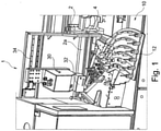
- a coating device 1 for coating workpieces 2 as a preferred embodiment of the present invention is in figure 1 shown schematically in a perspective view.
- the coating device 1 is used in the present embodiment for coating plate-shaped workpieces 2, which at least partially consist of wood, wood-based materials, plastic or the like, such as are used today in the furniture and component industry. It can be a wide variety of workpieces such as solid wood or chipboard, lightweight panels, sandwich panels, skirting boards, profiles for profile wrapping, etc. However, it should be noted that the present invention is not limited to such workpieces.
- the coating device 1 initially comprises a conveyor device 4, which in the present embodiment is designed as a continuous conveyor device, for example in the form of a roller conveyor, belt conveyor or the like.
- the conveyor device 4 is used to move the workpieces 2 in one direction (from right to left in figure 1 ) to promote.
- a feed device 10 for feeding a coating material 12 is arranged next to the conveyor device 4, which in the present embodiment can feed several different coating materials.
- the coating material can be, for example, an edge material for a narrow surface of the workpiece, but also a cover material for a wide surface or any other desired surface of the workpiece 2.
- the feed device 10 contains a supply of coating material 12, which can consist of a wide variety of materials, such as plastic, veneer, paper, cardboard, metal, etc. and various combinations thereof.
- the coating material can be provided, for example, in roll form (possibly in a cassette), but also in the form of individual sections.
- At least one coating material contains an integral or discrete layer containing energized adhesive properties.
- an integral coating material can be formed, for example, by a plastic material that contains a layer that develops adhesive properties as a result of the energy supply. If a discrete layer is provided, the rest of the coating material can in principle consist of any material. In any case, the discrete layer is arranged on the side of the coating material facing the workpiece.
- the feed device 10 feeds the coating material 12 to a pressing device 20 for pressing the coating material 12 onto a surface 2a of the workpiece 2 .
- the pressure device 20 is a pressure roller (instead of a pressure roller, for example, belts, shoes or the like can also be used), which rolls on the surface 2a of the workpiece 2 and in this way the coating material 12 on the surface 2a of the workpiece 2 presses.
- the coating device 1 comprises a first joining device in the form of an energy source 30 for applying energy to the adhesive agent or agent that can be made adhesive of the coating material 12.
- an energy source 30 for applying energy to the adhesive agent or agent that can be made adhesive of the coating material 12.
- energy sources 30 can be considered, such as lasers, infrared sources, ultrasonic sources, magnetic field sources , microwave source, plasma source, gassing source, etc. All of these energy sources 30 provide energy in a directed form and direct it at the adhesive or bondable agent that is applied as an integral or discrete part of the coating material 12 .
- the energy provided by the energy source passes through a focusing device 32 which is set up to direct the energy provided by the energy source 30 onto selected areas of the adhesive to be activated or applied.
- the focusing device 32 can be a lens. However, it should be noted that, depending on the energy source 30, different focusing devices 32 can be used, in which case the focusing device can be set up in each case to adjust the spread and, if appropriate, also the intensity of the energy applied. In this way, the focusing device 32 directs the energy provided by the energy source 30 into the area immediately upstream of a pressing area in which the coating material 12 is pressed onto the surface 2a of the workpiece 2 .
- This operation of energy source 30 and also of focusing device 32 is controlled by a control device (not shown in detail), with the control device in particular adjusting the output of energy source 30 to the properties and dimensions of the adhesive or the adhesive that can be made adhesive, and the relative speed between energy source 30 and the adhesive or Coating material 12 agrees.
- the control device can also evaluate information from sensors that monitor the operation of the coating device, for example sensors that are arranged in the area of the pressing area and record, for example, the temperature of the coating material 12 applied. Based on this information, the controller cannot control only the energy source 30, but optionally also the focusing device 32.
- the first joining device or energy source 30 is mounted by means of a linear guide 34 in such a way that the first joining device 30 lies between an in 1 shown joining position and an in 2 rest position shown is movable.
- This movement of the first joining device 30 can, for example, take place manually or possibly also by means of a drive (not shown).
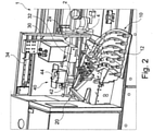
- the coating device 1 in the present embodiment comprises a second joining device 40, which is 2 is shown schematically and is also used to apply and/or activate an adhesive on a coating material 12 fed in the feed device 10 and/or on a surface 2a of a workpiece 2 to be coated.
- the second joining device 40 is constructed in the manner of a classic gluing technology and includes a glue reservoir 44 in which, for example, hot-melt adhesive granules are stored, the hot-melt adhesive granules being able to be brought to the desired melting temperature by means of a heating device not shown in detail.
- the second joining device 40 in the present embodiment has a glue application roller 42, by means of which the melted adhesive can be applied to the coating material 12 or the surface 2a of the workpiece.
- the second joining device 40 is inserted in a receptacle 46 of the device 1 in such a way that it can be removed again if necessary—possibly also manually.
- a quick-release coupling or the like can be provided in the latter, for example.
- the operation of the coating device 1 according to the invention takes place, for example, as follows.
- the first joining device 30 is in the in 1 shown joining position. In this position, the first joining device 30 can apply energy to the supplied coating material 12 or to the surface 2a of the workpiece 2 to be coated, in order to activate an adhesive agent provided there.
- the coating material 12 is then pressed onto the workpiece surface 2a to be coated by means of the pressure roller 20 , so that the coating material 12 is firmly bonded to the workpiece 2 .
- the first joining device 30 is moved from the joining position to the in 2 moved or moved shown rest position.
- the second joining device 40 is now inserted into the receptacle 46 of the coating device 1 and is located there in its joining position.
- Coating material 12 supplied by the second joining device 40 or the surface 2a of the workpiece 2 to be coated is now provided with adhesive and the coating material 12 is firmly attached to the surface 2a of the workpiece 2 to be coated by means of the pressure roller 20 .
- the second joining device 40 After completion of the necessary processing using the second joining device 40, it can be removed from the receptacle 46 in order to then move the first joining device 30 from its rest position to the in 1 to move the joining position shown. A coating process can now be carried out again using the first joining device 30 .
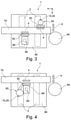
- FIG 3 shows a schematic plan view of a device 1 for coating workpieces 2.
- the device 1 shown is embodied as a machining center, for example, which has a clamping table 90 that is stationary or, if appropriate, movable within limits, on which the workpieces 2 can be clamped.
- the clamping table can also be designed as a turntable, for example.
- a boom or portal 70 extends above the clamping table and can be moved along the clamping table 90 perpendicular to its direction of extension. It should be noted here that a device according to the invention can also have a number of cantilevers and/or portals, which can each be equipped with one or more suitable devices. Furthermore, it is possible, particularly in the case of movable clamping table(s), for at least one guide device to be arranged in a stationary manner.
- a first joining device 50 is provided on the guide device 70 via a compound slide 92, on which in turn a combined feed device 10 and pressing device 20 is arranged.
- the first joining device 50 can be selected, for example, in accordance with the first joining device described above.
- a spindle unit 80 is provided via a further compound slide 92, into which processing tools and processing units can be exchanged via an interface with a (HSK) mount.
- the interface can be a universal interface, for example, as described in the patent application EP 0 743 139 is disclosed to the applicant.
- a second joining device 60 is exchanged, which can be, for example, a gluing unit working with hot-melt adhesive.
- the gluing unit 60 has a connection section which is inserted into the (HSK) receptacle of the spindle unit 80 is exchangeable.
- a magazine 94 for machining tools and machining units is provided at the right outer end of the guide device 70 and is designed in such a way that the spindle unit 80 is automatically supplied with machining tools and machining units including the second joining device 60 . It is also possible for several joining devices 60 to be kept available in the magazine 94, which are exchanged in the spindle unit 80 as required.
- the in 3 Machining center shown a complete or at least extensive processing and finishing of workpieces 2, wherein different coating technologies can be used as required.
- An alternative embodiment of the in 3 Machining center 1 shown is in 4 shown in a schematic plan view as a third preferred embodiment of the invention.
- the embodiment shown is characterized in that the first joining device 50 is operatively coupled to the second spindle unit 80 or to its compound slide 92, so that both units can be moved together.
- the second joining device 50 can optionally be arranged on the opposite side of the guide device 70 and can nevertheless be coupled to the spindle unit 80 via a suitable connection.
- machining center according to the invention or a similar device according to the invention therefore does not necessarily have to have a permanently installed joining device, but can also contain several joining devices stored in a magazine or the like, which can be exchanged alternately or simultaneously in one or more spindle units.
Landscapes
- Engineering & Computer Science (AREA)
- Manufacturing & Machinery (AREA)
- Life Sciences & Earth Sciences (AREA)
- Mechanical Engineering (AREA)
- Wood Science & Technology (AREA)
- Forests & Forestry (AREA)
- Physics & Mathematics (AREA)
- Thermal Sciences (AREA)
- Application Of Or Painting With Fluid Materials (AREA)
- Coating Apparatus (AREA)
- Veneer Processing And Manufacture Of Plywood (AREA)
- Lining Or Joining Of Plastics Or The Like (AREA)
Claims (13)
- Installation (1) pour le revêtement de pièces (2), préférentiellement au moins partiellement en bois, matériaux ligneux, matière synthétique, aluminium ou similaires, comprenant :un dispositif d'avance (10) pour l'amenée d'un matériau de revêtement (12),un dispositif de serrage (20) pour le serrage du matériau de revêtement (12) contre une surface (2a) d'une pièce (2),un dispositif de convoyage (4) pour le déclenchement d'un déplacement relatif entre le dispositif de serrage (20) et la pièce (2) respective, etun premier dispositif d'assemblage (30 ; 50) pour l'activation d'un adhésif sur un matériau de revêtement (12) amené dans le dispositif d'avance (10), dans laquellel'installation comprend en outre au moins un deuxième dispositif d'assemblage (40 ; 60) pour l'application et l'activation d'un adhésif sur une surface d'une pièce (2) à revêtir,dans laquelle au moins un des dispositifs d'assemblage (30, 40 ; 50, 60) comporte une source d'énergie,caractérisée en ce que la source d'énergie est sélectionnée dans le groupe composé de laser, de source de lumière infrarouge, de source d'ultrasons, de source de champ magnétique, de source de micro-ondes, de source de plasma et de source de gaz,dans laquelle le premier (30; 50) et le ou les deuxièmes (40 ; 60) dispositifs d'assemblage sont prévus pour activer l'adhésif en alternance.
- Installation selon la revendication 1, caractérisée en ce qu'au moins un dispositif d'assemblage est agencé de manière fixe.
- Installation selon l'une des revendications précédentes, caractérisée en ce qu'au moins un dispositif d'assemblage (30, 40 ; 50, 60) est déplaçable entre une position d'assemblage et une position de repos.
- Installation selon la revendication 3, caractérisée en ce qu'au moins un entraînement est prévu pour déplacer au moins un dispositif d'assemblage (30 ; 50, 60) entre une position d'assemblage et une position de repos.
- Installation selon l'une des revendications précédentes, caractérisée en ce qu'au moins un dispositif d'assemblage (40) peut être monté de manière amovible dans une réception (46), en particulier au moyen d'un raccord rapide dans une position d'assemblage de l'installation.
- Installation selon l'une des revendications précédentes, caractérisée en ce qu'au moins un dispositif d'assemblage (50, 60) est disposé sur un dispositif de guidage (70) préférentiellement en forme de barre, déplaçable de préférence perpendiculairement à sa direction d'extension, dans laquelle le ou les dispositifs d'assemblage (50, 60) sont préférentiellement déplaçables le long du dispositif de guidage (70).
- Installation selon la revendication 6, caractérisée en ce que celle-ci comporte en outre au moins une unité de broche (80) avec une réception pour le changement préférentiellement automatique d'outils d'usinage et/ou d'agrégats d'usinage.
- Installation selon la revendication 7, caractérisée en ce qu'au moins un dispositif d'assemblage (60) peut être changé dans la réception d'une unité de broche qui comporte préférentiellement un attachement HSK.
- Installation selon la revendication 7 ou 8, caractérisée en ce qu'au moins un dispositif d'assemblage (50) est accouplé à une unité de broche (80) pour permettre un déplacement commun.
- Installation selon l'une des revendications précédentes, caractérisée en ce qu'au moins un dispositif d'assemblage (50, 60) est accouplé à un dispositif de serrage (20) correspondant pour le serrage du matériau de revêtement (12) contre une surface (2a) d'une pièce (2) et préférentiellement aussi à un dispositif d'avance (10) pour l'amenée d'un matériau de revêtement (12).
- Procédé de revêtement de pièces (2), préférentiellement au moins partiellement en bois, matériaux ligneux, matière synthétique, aluminium ou similaires, recourant à une installation (1), laquelle installation comporteun dispositif d'avance (10) pour l'amenée d'un matériau de revêtement (12),un dispositif de serrage (20) pour le serrage du matériau de revêtement (12) contre une surface (2a) d'une pièce (2),un dispositif de convoyage (4) pour le déclenchement d'un déplacement relatif entre le dispositif de serrage (20) et la pièce (2) respective, etun premier dispositif d'assemblage (30 ; 50) pour l'activation d'un adhésif sur un matériau de revêtement (12) avancé dans le dispositif d'avance (10), dans laquellel'installation comprend en outre au moins un deuxième dispositif d'assemblage (40 ; 60) pour l'application et l'activation d'un adhésif sur une surface d'une pièce (2) à revêtir,dans lequel au moins un des dispositifs d'assemblage (30 ; 50) comporte une source d'énergie, laquellesource d'énergie est sélectionnée dans le groupe composé de laser, de source de lumière infrarouge, de source d'ultrasons, de source de champ magnétique, de source de micro-ondes, de source de plasma et de source de gaz,dans lequel le premier (30; 50) et le ou les deuxièmes (40; 60) dispositifs d'assemblage sont prévus pour activer l'adhésif en alternance,dans lequel le procédé présente les étapes suivantes :déclenchement d'un déplacement relatif entre le dispositif de serrage (20) et la pièce (2) respective au moyen du dispositif de convoyage (4),amenée du matériau de revêtement (12) au moyen du dispositif d'avance (10),activation d'un adhésif sur un matériau de revêtement (12) avancé dans le dispositif d'avance (10) au moyen du premier dispositif d'assemblage (30 ; 50), et enfinapplication et/ou activation d'un adhésif sur une surface d'une autre pièce (2) à revêtir au moyen du deuxième dispositif d'assemblage (40 ; 60).
- Procédé selon la revendication 11, caractérisé en ce que le premier dispositif d'assemblage (30 ; 50) est mis en mouvement, en étant notamment déplacé d'une position d'assemblage vers une position de repos après l'activation d'un adhésif.
- Procédé selon la revendication 11, caractérisé en ce que le deuxième dispositif d'assemblage (40; 60) est mis en mouvement, en étant notamment déplacé ou manuellement monté vers une position d'assemblage avant l'application et/ou l'activation d'un adhésif.
Priority Applications (7)
| Application Number | Priority Date | Filing Date | Title |
|---|---|---|---|
| DE202009019008.0U DE202009019008U1 (de) | 2009-04-22 | 2009-04-22 | Vorrichtung zum Beschichten von Werkstücken |
| ES09158457T ES2459296T5 (es) | 2009-04-22 | 2009-04-22 | Dispositivo y procedimiento para el recubrimiento de piezas de trabajo |
| EP09158457.3A EP2243619B2 (fr) | 2009-04-22 | 2009-04-22 | Dispositif et procédé destinés au revêtement de pièces à usiner |
| CN201010168550.6A CN101890738B (zh) | 2009-04-22 | 2010-04-22 | 用于涂覆工件的装置和方法 |
| US12/765,187 US20100269971A1 (en) | 2009-04-22 | 2010-04-22 | Device and method for coating workpieces |
| US15/390,956 US10307956B2 (en) | 2009-04-22 | 2016-12-27 | Device and method for coating workpieces |
| US16/374,333 US10857725B2 (en) | 2009-04-22 | 2019-04-03 | Device and method for coating workpieces |
Applications Claiming Priority (1)
| Application Number | Priority Date | Filing Date | Title |
|---|---|---|---|
| EP09158457.3A EP2243619B2 (fr) | 2009-04-22 | 2009-04-22 | Dispositif et procédé destinés au revêtement de pièces à usiner |
Publications (4)
| Publication Number | Publication Date |
|---|---|
| EP2243619A1 EP2243619A1 (fr) | 2010-10-27 |
| EP2243619A8 EP2243619A8 (fr) | 2011-06-08 |
| EP2243619B1 EP2243619B1 (fr) | 2014-01-29 |
| EP2243619B2 true EP2243619B2 (fr) | 2022-03-16 |
Family
ID=40943810
Family Applications (1)
| Application Number | Title | Priority Date | Filing Date |
|---|---|---|---|
| EP09158457.3A Active EP2243619B2 (fr) | 2009-04-22 | 2009-04-22 | Dispositif et procédé destinés au revêtement de pièces à usiner |
Country Status (5)
| Country | Link |
|---|---|
| US (3) | US20100269971A1 (fr) |
| EP (1) | EP2243619B2 (fr) |
| CN (1) | CN101890738B (fr) |
| DE (1) | DE202009019008U1 (fr) |
| ES (1) | ES2459296T5 (fr) |
Families Citing this family (35)
| Publication number | Priority date | Publication date | Assignee | Title |
|---|---|---|---|---|
| DE102009021676A1 (de) * | 2009-05-18 | 2010-11-25 | Homag Holzbearbeitungssysteme Ag | Zufuhrvorrichtung |
| DE102009041928B4 (de) * | 2009-09-17 | 2012-03-29 | Ima Klessmann Gmbh Holzbearbeitungssysteme | Verfahren zur Oberflächenglättung und Vorrichtung zur Flächenkaschierung |
| DE102011014995A1 (de) * | 2011-03-25 | 2012-09-27 | Ima Klessmann Gmbh Holzbearbeitungssysteme | Vorrichtung zur Bearbeitung von Werkstücken |
| DE102011007517A1 (de) * | 2011-04-15 | 2012-10-18 | Homag Holzbearbeitungssysteme Gmbh | Bearbeitungsmaschine |
| JP6009318B2 (ja) * | 2012-11-01 | 2016-10-19 | 早川ゴム株式会社 | レーザー光を用いた接合方法 |
| DE102013001893A1 (de) * | 2013-02-02 | 2014-08-07 | Ima Klessmann Gmbh Holzbearbeitungssysteme | Bekantungsvorrichtung |
| DE102013202938A1 (de) | 2013-02-22 | 2014-08-28 | Homag Holzbearbeitungssysteme Gmbh | Vorrichtung zum Beschichten von Werkstücken |
| ITBO20130084A1 (it) * | 2013-02-28 | 2014-08-29 | Biesse Spa | Macchina per la bordatura di pannelli di legno o simili |
| DE102013012644A1 (de) | 2013-07-30 | 2015-02-05 | Ima Klessmann Gmbh Holzbearbeitungssysteme | Beschichtungsvorrichtung sowie Aktivierungsmodul für eine Beschichtungsvorrichtung |
| ITBO20130445A1 (it) * | 2013-08-06 | 2015-02-07 | Biesse Spa | Macchina per la lavorazione di pannelli di legno o simili |
| DE102013216113A1 (de) * | 2013-08-14 | 2015-03-05 | Homag Holzbearbeitungssysteme Gmbh | Beschichtungsaggregat |
| DE102013219270A1 (de) * | 2013-09-25 | 2015-04-09 | Homag Holzbearbeitungssysteme Gmbh | Wechselsystem für Beschichtungsmaschine sowie Verfahren |
| DE102013222636A1 (de) * | 2013-11-07 | 2015-05-07 | Homag Holzbearbeitungssysteme Gmbh | Verfahren zum Aufbringen einer Beschichtung auf Werkstücke und Vorrichtung zum Beschichten von Werkstücken |
| DE102014103725A1 (de) | 2014-03-19 | 2015-10-08 | Holz-Her Gmbh | Vorrichtung zum Fixieren eines Kantenmaterials |
| DE102014107492A1 (de) * | 2014-05-27 | 2015-12-03 | Mhf Gmbh | Verfahren zum Glätten von Werkstückkanten |
| EP3050657B1 (fr) * | 2015-02-02 | 2018-01-17 | Essetre - S.P.A. | Appareil automatisé de traitement de matière ligneuse faite de panneaux |
| DE102015213358A1 (de) * | 2015-07-16 | 2017-01-19 | Homag Holzbearbeitungssysteme Gmbh | Zuführeinrichtung für Beschichtungsmaterial |
| ITUB20152366A1 (it) * | 2015-07-21 | 2017-01-21 | Biesse Spa | Macchina per la bordatura di pannelli di legno o simili |
| DE202015105929U1 (de) | 2015-11-06 | 2015-11-20 | Holz-Her Gmbh | Kantenbearbeitungsmaschine |
| DE202015105931U1 (de) | 2015-11-06 | 2015-11-20 | Holz-Her Gmbh | Kantenbeschichtungsmaschine |
| DE102016204249A1 (de) | 2016-03-15 | 2017-09-21 | Homag Gmbh | Vorrichtung zum Bearbeiten und/oder Beschichten eines Werkstücks |
| DE102016109362A1 (de) * | 2016-05-20 | 2017-11-23 | Fritz Egger Gmbh & Co. Og | Vorrichtung und Verfahren zum Anbringen eines Kantenprofils sowie Möbelteil |
| DE102017208406A1 (de) * | 2017-05-18 | 2018-11-22 | Homag Gmbh | Vorrichtung und Verfahren zum Aktivieren von Haftmittel |
| DE102017117714A1 (de) * | 2017-08-04 | 2019-02-07 | Homag Gmbh | Verfahren zur Beschichtung einer Oberfläche mittels einem profiliertem Beschichtungsmaterial sowie Beschichtungsmaterial |
| DE102017122701A1 (de) | 2017-09-29 | 2019-04-04 | Homag Gmbh | Beschichtungsvorrichtung sowie Beschichtungsverfahren |
| IT201800001761A1 (it) * | 2018-01-24 | 2019-07-24 | Biesse Spa | Gruppo bordatore e metodo per la bordatura di pannelli di legno o simili |
| DE102019113794A1 (de) * | 2019-05-23 | 2020-11-26 | Homag Gmbh | Vorrichtung und Verfahren zum Beschichten von Werkstücken |
| DE102019113932A1 (de) * | 2019-05-24 | 2020-11-26 | Homag Gmbh | Verfahren zum Beschichten eines Bauteils sowie Beschichtungsvorrichtung |
| DE102019120377A1 (de) | 2019-07-29 | 2021-02-04 | Ima Schelling Deutschland Gmbh | Vorrichtung, insbesondere Softforming-Vorrichtung, zum Anbringen von Kantenstreifen |
| DE102019133335A1 (de) * | 2019-12-06 | 2021-06-10 | Homag Gmbh | Vorrichtung sowie ein Verfahren zum Beschichten einer Fläche eines Werkstücks |
| DE102020105320A1 (de) | 2020-02-28 | 2021-09-02 | Homag Gmbh | Zuführsystem für bandförmiges Material sowie Beschichtungsvorrichtung |
| DE102020121303A1 (de) | 2020-08-13 | 2022-02-17 | Homag Gmbh | Vorrichtung und Verfahren zum Beschichten eines plattenförmigen Werkstücks |
| DE102021117813A1 (de) | 2021-07-09 | 2023-01-12 | Homag Gmbh | Verfahren zum Beschichten eines Werkstücks, Beschichtungseinrichtung und Computerprogramm zum Einrichten einer Beschichtungseinrichtung |
| DE102021133043A1 (de) | 2021-12-14 | 2023-06-15 | Homag Gmbh | Verfahren zum Herstellen eines Werkstücks |
| CN114633338B (zh) * | 2022-04-24 | 2022-10-21 | 佛山豪德数控机械有限公司 | 一种多工位封边机 |
Citations (26)
| Publication number | Priority date | Publication date | Assignee | Title |
|---|---|---|---|---|
| DE2722225A1 (de) † | 1977-05-17 | 1978-11-23 | Torwegge Maschf F | Kantenanleimmaschine |
| US4155798A (en) † | 1966-11-11 | 1979-05-22 | Becker Otto A | Protection from corrosion of resistance-welded sheet metal covered with non-metallic layers |
| US4226661A (en) † | 1978-12-19 | 1980-10-07 | Haggar Company | Apparatus and method for prefabricating pockets |
| DE3415747A1 (de) † | 1984-03-02 | 1985-09-12 | Interholz Technik Gmbh, 7800 Freiburg | Verfahren zum aufkleben von kanten an brett- oder plattenfoermige, flaechige werkstuecke und vorrichtung zur durchfuehrung des verfahrens |
| EP0276358A2 (fr) † | 1987-01-26 | 1988-08-03 | IMA-Norte Maschinenfabriken Klessmann GmbH & Co. | Dispositif de collage de bordures |
| EP0292813A2 (fr) † | 1987-05-26 | 1988-11-30 | REICH Spezialmaschinen GmbH | Procédé et dispositif pour joindre des éléments latéraux aux parties frontales d'ouvrages en forme de plaque |
| DE4216191A1 (de) † | 1992-05-15 | 1993-11-18 | Friz Maschinenbau Gmbh | Maschine zum Aufbringen verschiedener Schmelzklebstoffarten auf einem Beschichtungs- bzw. Ummantelungsmaterial |
| EP0743139A1 (fr) † | 1995-05-15 | 1996-11-20 | Homag Maschinenbau Ag | Centre d'usinage avec une broche pour porter des outils et des groupes d'outils pour l'usinage de pièces en bois ou matière plastique |
| US5954918A (en) † | 1997-09-11 | 1999-09-21 | Cam Industries, Inc. | Tape wrapping machine |
| DE19837036A1 (de) † | 1998-08-14 | 2000-02-17 | Homag Maschinenbau Ag | Stegkantenaggregat |
| DE19955575A1 (de) † | 1999-11-18 | 2001-05-23 | Brandt Kantentechnik Gmbh | Verfahren und Vorrichtung zum Anhaften eines Deckmaterials an Werkstückoberflächen von fortlaufend bewegten oder stationär angeordneten platten- oder leistenförmigen Werkstücken |
| DE10234618A1 (de) † | 2001-07-27 | 2003-02-13 | Biesse Spa | Baueinheit zum Aufbringen eines Randstreifens auf Tafeln aus Holz oder Ähnlichem |
| US20030217807A1 (en) † | 2002-01-25 | 2003-11-27 | Leif Lesmann | Method and apparatus for gluing |
| EP1386720A2 (fr) † | 2002-07-31 | 2004-02-04 | Homag Holzbearbeitungssysteme AG | Procédé pour recouvrir des plaques avec une feuille décorative |
| US20040091694A1 (en) † | 2002-07-31 | 2004-05-13 | Holzer Mark R. | Induction bondable high-pressure laminate |
| EP1445082A2 (fr) † | 2003-02-07 | 2004-08-11 | Schulte- Göbel Christof | Encolleuse de chants |
| WO2004085152A1 (fr) † | 2003-03-24 | 2004-10-07 | Homag Holzbearbeitungssysteme Ag | Procede et dispositif pour produire un panneau sandwich |
| DE102005015295A1 (de) † | 2005-04-01 | 2006-10-19 | Billhöfer Maschinenfabrik GmbH & Co. KG | Vorrichtung und Verfahren zum Beschichten eines metallischen Trägermaterials |
| EP1800813A2 (fr) † | 2005-11-23 | 2007-06-27 | Technische Universität Dresden | Procédé de revêtement de composants |
| EP1932637A2 (fr) † | 2006-12-11 | 2008-06-18 | SCM GROUP S.p.A. | Procédé et appareil pour appliquer un bord de protection et panneau |
| EP1990152A1 (fr) † | 2007-05-10 | 2008-11-12 | Homag Holzbearbeitungssysteme AG | Dispositif et procédé de collage de bordures |
| DE202007011911U1 (de) † | 2007-08-24 | 2009-01-08 | Rehau Ag + Co | Kantenleiste für Möbelstücke |
| EP2052822A1 (fr) † | 2007-10-22 | 2009-04-29 | SCM GROUP S.p.A. | Procédé et appareil d'emboîture |
| EP2065217A1 (fr) † | 2007-11-30 | 2009-06-03 | Homag Holzbearbeitungssysteme AG | Dispositif et procédé destinés à l'échantillonnage d'une pièce à usiner utilisant des matériaux en bandes |
| EP2065186A1 (fr) † | 2007-11-30 | 2009-06-03 | Homag Holzbearbeitungssysteme AG | Procédé destiné à la fabrication d'un panneau de construction léger et dispositif d'exécution du procédé |
| EP2191947A1 (fr) † | 2008-12-01 | 2010-06-02 | Homag Holzbearbeitungssysteme AG | Dispositif et procédé destinés au revêtement de pièces à usiner |
Family Cites Families (19)
| Publication number | Priority date | Publication date | Assignee | Title |
|---|---|---|---|---|
| US2796095A (en) * | 1952-11-29 | 1957-06-18 | Handy Mfg Company | Clamping machine with flexible band work engaging means |
| US3649417A (en) * | 1970-01-29 | 1972-03-14 | Manuel Izen | Automatic edge banding apparatus |
| US3753832A (en) * | 1971-02-08 | 1973-08-21 | Westvaco Corp | Edge banding machine |
| US4067762A (en) * | 1977-02-15 | 1978-01-10 | Yerger Bros. Inc. | Portable edge bander |
| US4222812A (en) * | 1978-06-29 | 1980-09-16 | Lof Plastics, Inc. | Hot air edge banding machine |
| GB2081642B (en) * | 1980-08-11 | 1984-05-16 | Janssens W J Ind Nz Ltd | Method and apparatus for adhering bands or tapes to surfaces |
| US4597821A (en) * | 1983-08-26 | 1986-07-01 | Munro Alick R | Portable edge bander for hand held and table mounted operation |
| US4846921A (en) * | 1987-11-06 | 1989-07-11 | The Loveshaw Corporation | Vertical tape sealing of carton end walls |
| US5246533A (en) * | 1991-11-05 | 1993-09-21 | Marunaka Kakoki Co., Ltd. | Apparatus for press-bonding tape onto edges of workpiece |
| US6467522B1 (en) * | 1999-07-27 | 2002-10-22 | Castle, Inc. | Edge banding apparatus and method |
| ES2394249T3 (es) * | 2000-08-18 | 2013-01-30 | O'connell, Gregory John | Aparato de modificación de ribete |
| DE10051201A1 (de) * | 2000-10-16 | 2002-04-25 | Nordson Corp | Vorrichtung zum flächigen Auftragen von fließfähigem Klebstoff auf ein relativ zu der Vorrichtung bewegbares Bandmaterial, insbesondere Möbelumleimer |
| DE10124688A1 (de) * | 2001-05-18 | 2002-11-28 | Klebchemie, M.G. Becker Gmbh & Co Kg | Verfahren und Vorrichtung zur Herstellung von Furnieren und von furnierten Teilen sowie Furniere und furnierte Teile |
| JP3871974B2 (ja) * | 2001-12-17 | 2007-01-24 | 株式会社名南製作所 | ベニヤ単板の接合方法及び接合装置 |
| NZ526360A (en) * | 2003-05-30 | 2005-11-25 | Gregory John O Connell | A Panel Edge Modification Device or Unit for a Contour Edge Banding Device |
| US7507295B2 (en) * | 2005-03-22 | 2009-03-24 | Nordson Corporation | Adhesive dispenser |
| US8127711B2 (en) * | 2007-07-05 | 2012-03-06 | Nordson Corporation | Mounting systems for an adhesive application system and methods for applying adhesive |
| US20090120249A1 (en) * | 2007-11-14 | 2009-05-14 | Achim Gauss | Device For Refining Workpieces |
| CN101274441A (zh) * | 2008-04-24 | 2008-10-01 | 江苏大江木业有限公司 | 连续辊压中(高)密度纤维板直接贴面工艺及其设备 |
-
2009
- 2009-04-22 DE DE202009019008.0U patent/DE202009019008U1/de not_active Expired - Lifetime
- 2009-04-22 ES ES09158457T patent/ES2459296T5/es active Active
- 2009-04-22 EP EP09158457.3A patent/EP2243619B2/fr active Active
-
2010
- 2010-04-22 CN CN201010168550.6A patent/CN101890738B/zh active Active
- 2010-04-22 US US12/765,187 patent/US20100269971A1/en not_active Abandoned
-
2016
- 2016-12-27 US US15/390,956 patent/US10307956B2/en active Active
-
2019
- 2019-04-03 US US16/374,333 patent/US10857725B2/en active Active
Patent Citations (28)
| Publication number | Priority date | Publication date | Assignee | Title |
|---|---|---|---|---|
| US4155798A (en) † | 1966-11-11 | 1979-05-22 | Becker Otto A | Protection from corrosion of resistance-welded sheet metal covered with non-metallic layers |
| DE2722225A1 (de) † | 1977-05-17 | 1978-11-23 | Torwegge Maschf F | Kantenanleimmaschine |
| US4226661A (en) † | 1978-12-19 | 1980-10-07 | Haggar Company | Apparatus and method for prefabricating pockets |
| DE3415747A1 (de) † | 1984-03-02 | 1985-09-12 | Interholz Technik Gmbh, 7800 Freiburg | Verfahren zum aufkleben von kanten an brett- oder plattenfoermige, flaechige werkstuecke und vorrichtung zur durchfuehrung des verfahrens |
| EP0276358A2 (fr) † | 1987-01-26 | 1988-08-03 | IMA-Norte Maschinenfabriken Klessmann GmbH & Co. | Dispositif de collage de bordures |
| EP0292813A2 (fr) † | 1987-05-26 | 1988-11-30 | REICH Spezialmaschinen GmbH | Procédé et dispositif pour joindre des éléments latéraux aux parties frontales d'ouvrages en forme de plaque |
| DE4216191A1 (de) † | 1992-05-15 | 1993-11-18 | Friz Maschinenbau Gmbh | Maschine zum Aufbringen verschiedener Schmelzklebstoffarten auf einem Beschichtungs- bzw. Ummantelungsmaterial |
| EP0743139A1 (fr) † | 1995-05-15 | 1996-11-20 | Homag Maschinenbau Ag | Centre d'usinage avec une broche pour porter des outils et des groupes d'outils pour l'usinage de pièces en bois ou matière plastique |
| US5954918A (en) † | 1997-09-11 | 1999-09-21 | Cam Industries, Inc. | Tape wrapping machine |
| DE19837036A1 (de) † | 1998-08-14 | 2000-02-17 | Homag Maschinenbau Ag | Stegkantenaggregat |
| DE19955575A1 (de) † | 1999-11-18 | 2001-05-23 | Brandt Kantentechnik Gmbh | Verfahren und Vorrichtung zum Anhaften eines Deckmaterials an Werkstückoberflächen von fortlaufend bewegten oder stationär angeordneten platten- oder leistenförmigen Werkstücken |
| DE10234618A1 (de) † | 2001-07-27 | 2003-02-13 | Biesse Spa | Baueinheit zum Aufbringen eines Randstreifens auf Tafeln aus Holz oder Ähnlichem |
| US20030217807A1 (en) † | 2002-01-25 | 2003-11-27 | Leif Lesmann | Method and apparatus for gluing |
| US20040091694A1 (en) † | 2002-07-31 | 2004-05-13 | Holzer Mark R. | Induction bondable high-pressure laminate |
| EP1386720A2 (fr) † | 2002-07-31 | 2004-02-04 | Homag Holzbearbeitungssysteme AG | Procédé pour recouvrir des plaques avec une feuille décorative |
| EP1445082A2 (fr) † | 2003-02-07 | 2004-08-11 | Schulte- Göbel Christof | Encolleuse de chants |
| WO2004085152A1 (fr) † | 2003-03-24 | 2004-10-07 | Homag Holzbearbeitungssysteme Ag | Procede et dispositif pour produire un panneau sandwich |
| DE102005015295A1 (de) † | 2005-04-01 | 2006-10-19 | Billhöfer Maschinenfabrik GmbH & Co. KG | Vorrichtung und Verfahren zum Beschichten eines metallischen Trägermaterials |
| EP1800813A2 (fr) † | 2005-11-23 | 2007-06-27 | Technische Universität Dresden | Procédé de revêtement de composants |
| DE102006056010A1 (de) † | 2005-11-23 | 2007-07-05 | Technische Universität Dresden | Verfahren zur Beschichtung von Bauteilen |
| EP1932637A2 (fr) † | 2006-12-11 | 2008-06-18 | SCM GROUP S.p.A. | Procédé et appareil pour appliquer un bord de protection et panneau |
| EP1990152A1 (fr) † | 2007-05-10 | 2008-11-12 | Homag Holzbearbeitungssysteme AG | Dispositif et procédé de collage de bordures |
| DE202007011911U1 (de) † | 2007-08-24 | 2009-01-08 | Rehau Ag + Co | Kantenleiste für Möbelstücke |
| EP2052822A1 (fr) † | 2007-10-22 | 2009-04-29 | SCM GROUP S.p.A. | Procédé et appareil d'emboîture |
| EP2065217A1 (fr) † | 2007-11-30 | 2009-06-03 | Homag Holzbearbeitungssysteme AG | Dispositif et procédé destinés à l'échantillonnage d'une pièce à usiner utilisant des matériaux en bandes |
| EP2065186A1 (fr) † | 2007-11-30 | 2009-06-03 | Homag Holzbearbeitungssysteme AG | Procédé destiné à la fabrication d'un panneau de construction léger et dispositif d'exécution du procédé |
| US20090139649A1 (en) † | 2007-11-30 | 2009-06-04 | Ludwig Albrecht | Device And Method For Patterning A Workpiece |
| EP2191947A1 (fr) † | 2008-12-01 | 2010-06-02 | Homag Holzbearbeitungssysteme AG | Dispositif et procédé destinés au revêtement de pièces à usiner |
Also Published As
| Publication number | Publication date |
|---|---|
| EP2243619A8 (fr) | 2011-06-08 |
| EP2243619A1 (fr) | 2010-10-27 |
| DE202009019008U1 (de) | 2015-05-27 |
| EP2243619B1 (fr) | 2014-01-29 |
| CN101890738A (zh) | 2010-11-24 |
| US20100269971A1 (en) | 2010-10-28 |
| US20170106581A1 (en) | 2017-04-20 |
| US10857725B2 (en) | 2020-12-08 |
| US20190224908A1 (en) | 2019-07-25 |
| CN101890738B (zh) | 2014-08-06 |
| ES2459296T5 (es) | 2022-06-29 |
| ES2459296T3 (es) | 2014-05-08 |
| US10307956B2 (en) | 2019-06-04 |
Similar Documents
| Publication | Publication Date | Title |
|---|---|---|
| EP2243619B2 (fr) | Dispositif et procédé destinés au revêtement de pièces à usiner | |
| EP2365899B1 (fr) | Dispositif pour le revêtement de pièces | |
| EP3461608B1 (fr) | Dispositif de revêtement ainsi que procédé de revêtement | |
| EP0728561B1 (fr) | Dispositif pour effectuer une séquence d'opérations sur des pièces à usiner en forme de plaques | |
| EP2345518B1 (fr) | Dispositif et procédé destinés au revêtement de pièces à usiner | |
| EP3429818B1 (fr) | Dispositif pour usiner et/ou recouvrir une pièce et procédé | |
| DE19955575A1 (de) | Verfahren und Vorrichtung zum Anhaften eines Deckmaterials an Werkstückoberflächen von fortlaufend bewegten oder stationär angeordneten platten- oder leistenförmigen Werkstücken | |
| DE60003094T2 (de) | Verfahren und Maschine zum Herstellen von Sandwichplatten | |
| EP2251166B1 (fr) | Agrégat de collage | |
| WO2020094283A1 (fr) | Procédé et dispositif pour le revêtement d'une pièce | |
| WO2013076205A1 (fr) | Ensemble buse pour dispositif applicateur de bande de chant, servant à la projection d'air chaud sur une bande de chant ou une pièce thermoactivable sans adhésif ou revêtue d'un adhésif thermocollant, et dispositif applicateur de bande de chant équipé d'un ensemble buse | |
| EP2340147A1 (fr) | Machine d'usinage pour usinage hexagonal | |
| EP1445082B1 (fr) | Encolleuse de chants | |
| EP1714756B1 (fr) | Centre d'usinage pour pièces en forme de plaque | |
| EP4000832A1 (fr) | Dispositif de revêtement, ainsi que procédé | |
| EP2100704A1 (fr) | Traitement simultané de plusieurs pièces à usiner | |
| EP1867488B1 (fr) | Procédé pour décorer la surface de pièces | |
| EP1792723B1 (fr) | Procédé et dispositif destinés à la fabrication d'un panneau de construction léger | |
| EP2769815B1 (fr) | Dispositif et procédé de revêtement de pièces usinées | |
| DE3713773C2 (de) | Verfahren und Vorrichtung zum kontinuierlichen Anleimen von Furnierstreifen auf Kanten von plattenförmigen Werkstücken | |
| EP3928939A1 (fr) | Dispositif et procédé de revêtement d'une pièce | |
| AT504611B1 (de) | Verfahren zur herstellung von über keilzinkenverbindungen zusammengesetzten werkstücken bestehenden bauelementen und vorrichtung zur durchführung dieses verfahrens | |
| DE102020117026A1 (de) | Vorrichtung und Verfahren zum Beschichten eines Werkstücks | |
| EP3653353B1 (fr) | Dispositif et procédé de revêtement d'une pièce | |
| DE102019113066A1 (de) | Verfahren und Appliziereinrichtung zum Applizieren eines bandförmigen Haftmittels sowie Beschichtungseinrichtung zum Beschichten plattenförmiger Werkstücke |
Legal Events
| Date | Code | Title | Description |
|---|---|---|---|
| PUAI | Public reference made under article 153(3) epc to a published international application that has entered the european phase |
Free format text: ORIGINAL CODE: 0009012 |
|
| AK | Designated contracting states |
Kind code of ref document: A1 Designated state(s): AT BE BG CH CY CZ DE DK EE ES FI FR GB GR HR HU IE IS IT LI LT LU LV MC MK MT NL NO PL PT RO SE SI SK TR |
|
| 17P | Request for examination filed |
Effective date: 20110329 |
|
| 17Q | First examination report despatched |
Effective date: 20110420 |
|
| REG | Reference to a national code |
Ref country code: DE Ref legal event code: R079 Ref document number: 502009008761 Country of ref document: DE Free format text: PREVIOUS MAIN CLASS: B29C0063000000 Ipc: B27D0005000000 |
|
| GRAP | Despatch of communication of intention to grant a patent |
Free format text: ORIGINAL CODE: EPIDOSNIGR1 |
|
| INTG | Intention to grant announced |
Effective date: 20130912 |
|
| RIC1 | Information provided on ipc code assigned before grant |
Ipc: B29K 311/14 20060101ALN20130902BHEP Ipc: B29C 63/02 20060101ALN20130902BHEP Ipc: B29C 63/48 20060101ALN20130902BHEP Ipc: B27D 5/00 20060101AFI20130902BHEP Ipc: B29C 63/00 20060101ALI20130902BHEP Ipc: B29K 305/02 20060101ALN20130902BHEP |
|
| GRAS | Grant fee paid |
Free format text: ORIGINAL CODE: EPIDOSNIGR3 |
|
| GRAA | (expected) grant |
Free format text: ORIGINAL CODE: 0009210 |
|
| AK | Designated contracting states |
Kind code of ref document: B1 Designated state(s): AT BE BG CH CY CZ DE DK EE ES FI FR GB GR HR HU IE IS IT LI LT LU LV MC MK MT NL NO PL PT RO SE SI SK TR |
|
| REG | Reference to a national code |
Ref country code: GB Ref legal event code: FG4D Free format text: NOT ENGLISH |
|
| REG | Reference to a national code |
Ref country code: CH Ref legal event code: EP |
|
| REG | Reference to a national code |
Ref country code: AT Ref legal event code: REF Ref document number: 651388 Country of ref document: AT Kind code of ref document: T Effective date: 20140215 |
|
| REG | Reference to a national code |
Ref country code: IE Ref legal event code: FG4D Free format text: LANGUAGE OF EP DOCUMENT: GERMAN |
|
| REG | Reference to a national code |
Ref country code: DE Ref legal event code: R096 Ref document number: 502009008761 Country of ref document: DE Effective date: 20140313 |
|
| REG | Reference to a national code |
Ref country code: ES Ref legal event code: FG2A Ref document number: 2459296 Country of ref document: ES Kind code of ref document: T3 Effective date: 20140508 |
|
| REG | Reference to a national code |
Ref country code: NL Ref legal event code: VDEP Effective date: 20140129 |
|
| REG | Reference to a national code |
Ref country code: LT Ref legal event code: MG4D |
|
| PG25 | Lapsed in a contracting state [announced via postgrant information from national office to epo] |
Ref country code: IS Free format text: LAPSE BECAUSE OF FAILURE TO SUBMIT A TRANSLATION OF THE DESCRIPTION OR TO PAY THE FEE WITHIN THE PRESCRIBED TIME-LIMIT Effective date: 20140529 Ref country code: NO Free format text: LAPSE BECAUSE OF FAILURE TO SUBMIT A TRANSLATION OF THE DESCRIPTION OR TO PAY THE FEE WITHIN THE PRESCRIBED TIME-LIMIT Effective date: 20140429 Ref country code: LT Free format text: LAPSE BECAUSE OF FAILURE TO SUBMIT A TRANSLATION OF THE DESCRIPTION OR TO PAY THE FEE WITHIN THE PRESCRIBED TIME-LIMIT Effective date: 20140129 |
|
| PG25 | Lapsed in a contracting state [announced via postgrant information from national office to epo] |
Ref country code: PT Free format text: LAPSE BECAUSE OF FAILURE TO SUBMIT A TRANSLATION OF THE DESCRIPTION OR TO PAY THE FEE WITHIN THE PRESCRIBED TIME-LIMIT Effective date: 20140529 Ref country code: FI Free format text: LAPSE BECAUSE OF FAILURE TO SUBMIT A TRANSLATION OF THE DESCRIPTION OR TO PAY THE FEE WITHIN THE PRESCRIBED TIME-LIMIT Effective date: 20140129 Ref country code: SE Free format text: LAPSE BECAUSE OF FAILURE TO SUBMIT A TRANSLATION OF THE DESCRIPTION OR TO PAY THE FEE WITHIN THE PRESCRIBED TIME-LIMIT Effective date: 20140129 Ref country code: NL Free format text: LAPSE BECAUSE OF FAILURE TO SUBMIT A TRANSLATION OF THE DESCRIPTION OR TO PAY THE FEE WITHIN THE PRESCRIBED TIME-LIMIT Effective date: 20140129 Ref country code: CY Free format text: LAPSE BECAUSE OF FAILURE TO SUBMIT A TRANSLATION OF THE DESCRIPTION OR TO PAY THE FEE WITHIN THE PRESCRIBED TIME-LIMIT Effective date: 20140129 |
|
| PG25 | Lapsed in a contracting state [announced via postgrant information from national office to epo] |
Ref country code: LV Free format text: LAPSE BECAUSE OF FAILURE TO SUBMIT A TRANSLATION OF THE DESCRIPTION OR TO PAY THE FEE WITHIN THE PRESCRIBED TIME-LIMIT Effective date: 20140129 Ref country code: HR Free format text: LAPSE BECAUSE OF FAILURE TO SUBMIT A TRANSLATION OF THE DESCRIPTION OR TO PAY THE FEE WITHIN THE PRESCRIBED TIME-LIMIT Effective date: 20140129 |
|
| REG | Reference to a national code |
Ref country code: DE Ref legal event code: R026 Ref document number: 502009008761 Country of ref document: DE |
|
| PG25 | Lapsed in a contracting state [announced via postgrant information from national office to epo] |
Ref country code: DK Free format text: LAPSE BECAUSE OF FAILURE TO SUBMIT A TRANSLATION OF THE DESCRIPTION OR TO PAY THE FEE WITHIN THE PRESCRIBED TIME-LIMIT Effective date: 20140129 Ref country code: RO Free format text: LAPSE BECAUSE OF FAILURE TO SUBMIT A TRANSLATION OF THE DESCRIPTION OR TO PAY THE FEE WITHIN THE PRESCRIBED TIME-LIMIT Effective date: 20140129 Ref country code: EE Free format text: LAPSE BECAUSE OF FAILURE TO SUBMIT A TRANSLATION OF THE DESCRIPTION OR TO PAY THE FEE WITHIN THE PRESCRIBED TIME-LIMIT Effective date: 20140129 Ref country code: CZ Free format text: LAPSE BECAUSE OF FAILURE TO SUBMIT A TRANSLATION OF THE DESCRIPTION OR TO PAY THE FEE WITHIN THE PRESCRIBED TIME-LIMIT Effective date: 20140129 |
|
| PLBI | Opposition filed |
Free format text: ORIGINAL CODE: 0009260 |
|
| PLBI | Opposition filed |
Free format text: ORIGINAL CODE: 0009260 |
|
| PG25 | Lapsed in a contracting state [announced via postgrant information from national office to epo] |
Ref country code: PL Free format text: LAPSE BECAUSE OF FAILURE TO SUBMIT A TRANSLATION OF THE DESCRIPTION OR TO PAY THE FEE WITHIN THE PRESCRIBED TIME-LIMIT Effective date: 20140129 Ref country code: MC Free format text: LAPSE BECAUSE OF FAILURE TO SUBMIT A TRANSLATION OF THE DESCRIPTION OR TO PAY THE FEE WITHIN THE PRESCRIBED TIME-LIMIT Effective date: 20140129 Ref country code: LU Free format text: LAPSE BECAUSE OF FAILURE TO SUBMIT A TRANSLATION OF THE DESCRIPTION OR TO PAY THE FEE WITHIN THE PRESCRIBED TIME-LIMIT Effective date: 20140422 Ref country code: SK Free format text: LAPSE BECAUSE OF FAILURE TO SUBMIT A TRANSLATION OF THE DESCRIPTION OR TO PAY THE FEE WITHIN THE PRESCRIBED TIME-LIMIT Effective date: 20140129 |
|
| REG | Reference to a national code |
Ref country code: CH Ref legal event code: PL |
|
| 26 | Opposition filed |
Opponent name: HOLZ-HER GMBH Effective date: 20141027 Opponent name: FELDER KG Effective date: 20141024 |
|
| PLAX | Notice of opposition and request to file observation + time limit sent |
Free format text: ORIGINAL CODE: EPIDOSNOBS2 |
|
| 26 | Opposition filed |
Opponent name: MASCHINENBAU HEBROCK GMBH Effective date: 20141028 Opponent name: SCM GROUP S.P.A. Effective date: 20141029 Opponent name: BIESSE S.P.A. Effective date: 20141029 |
|
| GBPC | Gb: european patent ceased through non-payment of renewal fee |
Effective date: 20140429 |
|
| REG | Reference to a national code |
Ref country code: DE Ref legal event code: R026 Ref document number: 502009008761 Country of ref document: DE Effective date: 20141024 |
|
| REG | Reference to a national code |
Ref country code: FR Ref legal event code: ST Effective date: 20141231 |
|
| REG | Reference to a national code |
Ref country code: IE Ref legal event code: MM4A |
|
| PG25 | Lapsed in a contracting state [announced via postgrant information from national office to epo] |
Ref country code: LI Free format text: LAPSE BECAUSE OF NON-PAYMENT OF DUE FEES Effective date: 20140430 Ref country code: CH Free format text: LAPSE BECAUSE OF NON-PAYMENT OF DUE FEES Effective date: 20140430 Ref country code: GB Free format text: LAPSE BECAUSE OF NON-PAYMENT OF DUE FEES Effective date: 20140429 |
|
| PG25 | Lapsed in a contracting state [announced via postgrant information from national office to epo] |
Ref country code: FR Free format text: LAPSE BECAUSE OF NON-PAYMENT OF DUE FEES Effective date: 20140430 |
|
| PG25 | Lapsed in a contracting state [announced via postgrant information from national office to epo] |
Ref country code: IE Free format text: LAPSE BECAUSE OF NON-PAYMENT OF DUE FEES Effective date: 20140422 |
|
| PLAF | Information modified related to communication of a notice of opposition and request to file observations + time limit |
Free format text: ORIGINAL CODE: EPIDOSCOBS2 |
|
| PG25 | Lapsed in a contracting state [announced via postgrant information from national office to epo] |
Ref country code: SI Free format text: LAPSE BECAUSE OF FAILURE TO SUBMIT A TRANSLATION OF THE DESCRIPTION OR TO PAY THE FEE WITHIN THE PRESCRIBED TIME-LIMIT Effective date: 20140129 |
|
| PLBB | Reply of patent proprietor to notice(s) of opposition received |
Free format text: ORIGINAL CODE: EPIDOSNOBS3 |
|
| PLAY | Examination report in opposition despatched + time limit |
Free format text: ORIGINAL CODE: EPIDOSNORE2 |
|
| PLAB | Opposition data, opponent's data or that of the opponent's representative modified |
Free format text: ORIGINAL CODE: 0009299OPPO |
|
| PG25 | Lapsed in a contracting state [announced via postgrant information from national office to epo] |
Ref country code: MT Free format text: LAPSE BECAUSE OF FAILURE TO SUBMIT A TRANSLATION OF THE DESCRIPTION OR TO PAY THE FEE WITHIN THE PRESCRIBED TIME-LIMIT Effective date: 20140129 |
|
| R26 | Opposition filed (corrected) |
Opponent name: FELDER KG Effective date: 20141024 |
|
| PG25 | Lapsed in a contracting state [announced via postgrant information from national office to epo] |
Ref country code: GR Free format text: LAPSE BECAUSE OF FAILURE TO SUBMIT A TRANSLATION OF THE DESCRIPTION OR TO PAY THE FEE WITHIN THE PRESCRIBED TIME-LIMIT Effective date: 20140430 Ref country code: BG Free format text: LAPSE BECAUSE OF FAILURE TO SUBMIT A TRANSLATION OF THE DESCRIPTION OR TO PAY THE FEE WITHIN THE PRESCRIBED TIME-LIMIT Effective date: 20140129 |
|
| PLAH | Information related to despatch of examination report in opposition + time limit modified |
Free format text: ORIGINAL CODE: EPIDOSCORE2 |
|
| PG25 | Lapsed in a contracting state [announced via postgrant information from national office to epo] |
Ref country code: TR Free format text: LAPSE BECAUSE OF FAILURE TO SUBMIT A TRANSLATION OF THE DESCRIPTION OR TO PAY THE FEE WITHIN THE PRESCRIBED TIME-LIMIT Effective date: 20140129 Ref country code: BE Free format text: LAPSE BECAUSE OF FAILURE TO SUBMIT A TRANSLATION OF THE DESCRIPTION OR TO PAY THE FEE WITHIN THE PRESCRIBED TIME-LIMIT Effective date: 20140430 Ref country code: HU Free format text: LAPSE BECAUSE OF FAILURE TO SUBMIT A TRANSLATION OF THE DESCRIPTION OR TO PAY THE FEE WITHIN THE PRESCRIBED TIME-LIMIT; INVALID AB INITIO Effective date: 20090422 |
|
| PLBC | Reply to examination report in opposition received |
Free format text: ORIGINAL CODE: EPIDOSNORE3 |
|
| PLAB | Opposition data, opponent's data or that of the opponent's representative modified |
Free format text: ORIGINAL CODE: 0009299OPPO |
|
| R26 | Opposition filed (corrected) |
Opponent name: MASCHINENBAU HEBROCK GMBH Effective date: 20141028 |
|
| PLAB | Opposition data, opponent's data or that of the opponent's representative modified |
Free format text: ORIGINAL CODE: 0009299OPPO |
|
| R26 | Opposition filed (corrected) |
Opponent name: MASCHINENBAU HEBROCK GMBH Effective date: 20141028 |
|
| PG25 | Lapsed in a contracting state [announced via postgrant information from national office to epo] |
Ref country code: MK Free format text: LAPSE BECAUSE OF FAILURE TO SUBMIT A TRANSLATION OF THE DESCRIPTION OR TO PAY THE FEE WITHIN THE PRESCRIBED TIME-LIMIT Effective date: 20140129 |
|
| PLBP | Opposition withdrawn |
Free format text: ORIGINAL CODE: 0009264 |
|
| PLAB | Opposition data, opponent's data or that of the opponent's representative modified |
Free format text: ORIGINAL CODE: 0009299OPPO |
|
| PLBP | Opposition withdrawn |
Free format text: ORIGINAL CODE: 0009264 |
|
| APBM | Appeal reference recorded |
Free format text: ORIGINAL CODE: EPIDOSNREFNO |
|
| APBP | Date of receipt of notice of appeal recorded |
Free format text: ORIGINAL CODE: EPIDOSNNOA2O |
|
| APAH | Appeal reference modified |
Free format text: ORIGINAL CODE: EPIDOSCREFNO |
|
| APAW | Appeal reference deleted |
Free format text: ORIGINAL CODE: EPIDOSDREFNO |
|
| APBM | Appeal reference recorded |
Free format text: ORIGINAL CODE: EPIDOSNREFNO |
|
| APBP | Date of receipt of notice of appeal recorded |
Free format text: ORIGINAL CODE: EPIDOSNNOA2O |
|
| APBM | Appeal reference recorded |
Free format text: ORIGINAL CODE: EPIDOSNREFNO |
|
| APBP | Date of receipt of notice of appeal recorded |
Free format text: ORIGINAL CODE: EPIDOSNNOA2O |
|
| APBQ | Date of receipt of statement of grounds of appeal recorded |
Free format text: ORIGINAL CODE: EPIDOSNNOA3O |
|
| APBQ | Date of receipt of statement of grounds of appeal recorded |
Free format text: ORIGINAL CODE: EPIDOSNNOA3O |
|
| PLBP | Opposition withdrawn |
Free format text: ORIGINAL CODE: 0009264 |
|
| APBU | Appeal procedure closed |
Free format text: ORIGINAL CODE: EPIDOSNNOA9O |
|
| PLAB | Opposition data, opponent's data or that of the opponent's representative modified |
Free format text: ORIGINAL CODE: 0009299OPPO |
|
| PUAH | Patent maintained in amended form |
Free format text: ORIGINAL CODE: 0009272 |
|
| STAA | Information on the status of an ep patent application or granted ep patent |
Free format text: STATUS: PATENT MAINTAINED AS AMENDED |
|
| 27A | Patent maintained in amended form |
Effective date: 20220316 |
|
| AK | Designated contracting states |
Kind code of ref document: B2 Designated state(s): AT BE BG CH CY CZ DE DK EE ES FI FR GB GR HR HU IE IS IT LI LT LU LV MC MK MT NL NO PL PT RO SE SI SK TR |
|
| REG | Reference to a national code |
Ref country code: DE Ref legal event code: R102 Ref document number: 502009008761 Country of ref document: DE |
|
| REG | Reference to a national code |
Ref country code: ES Ref legal event code: DC2A Ref document number: 2459296 Country of ref document: ES Kind code of ref document: T5 Effective date: 20220629 |
|
| P01 | Opt-out of the competence of the unified patent court (upc) registered |
Effective date: 20230529 |
|
| PGFP | Annual fee paid to national office [announced via postgrant information from national office to epo] |
Ref country code: DE Payment date: 20250423 Year of fee payment: 17 |
|
| PGFP | Annual fee paid to national office [announced via postgrant information from national office to epo] |
Ref country code: ES Payment date: 20250506 Year of fee payment: 17 |
|
| PGFP | Annual fee paid to national office [announced via postgrant information from national office to epo] |
Ref country code: IT Payment date: 20250428 Year of fee payment: 17 |
|
| PGFP | Annual fee paid to national office [announced via postgrant information from national office to epo] |
Ref country code: AT Payment date: 20250423 Year of fee payment: 17 |