EP3054880B1 - Système indicateur de vide qui évite la libération en l'absence d'un niveau de vide approprié - Google Patents
Système indicateur de vide qui évite la libération en l'absence d'un niveau de vide approprié Download PDFInfo
- Publication number
- EP3054880B1 EP3054880B1 EP14795869.8A EP14795869A EP3054880B1 EP 3054880 B1 EP3054880 B1 EP 3054880B1 EP 14795869 A EP14795869 A EP 14795869A EP 3054880 B1 EP3054880 B1 EP 3054880B1
- Authority
- EP
- European Patent Office
- Prior art keywords
- safety
- vacuum indicator
- container
- housing
- bone cement
- Prior art date
- Legal status (The legal status is an assumption and is not a legal conclusion. Google has not performed a legal analysis and makes no representation as to the accuracy of the status listed.)
- Active
Links
Images






Classifications
-
- B—PERFORMING OPERATIONS; TRANSPORTING
- B01—PHYSICAL OR CHEMICAL PROCESSES OR APPARATUS IN GENERAL
- B01F—MIXING, e.g. DISSOLVING, EMULSIFYING OR DISPERSING
- B01F33/00—Other mixers; Mixing plants; Combinations of mixers
- B01F33/70—Mixers specially adapted for working at sub- or super-atmospheric pressure, e.g. combined with de-foaming
-
- A—HUMAN NECESSITIES
- A61—MEDICAL OR VETERINARY SCIENCE; HYGIENE
- A61B—DIAGNOSIS; SURGERY; IDENTIFICATION
- A61B17/00—Surgical instruments, devices or methods
- A61B17/56—Surgical instruments or methods for treatment of bones or joints; Devices specially adapted therefor
- A61B17/58—Surgical instruments or methods for treatment of bones or joints; Devices specially adapted therefor for osteosynthesis, e.g. bone plates, screws or setting implements
- A61B17/88—Osteosynthesis instruments; Methods or means for implanting or extracting internal or external fixation devices
- A61B17/8802—Equipment for handling bone cement or other fluid fillers
-
- A—HUMAN NECESSITIES
- A61—MEDICAL OR VETERINARY SCIENCE; HYGIENE
- A61B—DIAGNOSIS; SURGERY; IDENTIFICATION
- A61B17/00—Surgical instruments, devices or methods
- A61B17/56—Surgical instruments or methods for treatment of bones or joints; Devices specially adapted therefor
- A61B17/58—Surgical instruments or methods for treatment of bones or joints; Devices specially adapted therefor for osteosynthesis, e.g. bone plates, screws or setting implements
- A61B17/88—Osteosynthesis instruments; Methods or means for implanting or extracting internal or external fixation devices
- A61B17/8802—Equipment for handling bone cement or other fluid fillers
- A61B17/8805—Equipment for handling bone cement or other fluid fillers for introducing fluid filler into bone or extracting it
- A61B17/8825—Equipment for handling bone cement or other fluid fillers for introducing fluid filler into bone or extracting it characterised by syringe details
-
- A—HUMAN NECESSITIES
- A61—MEDICAL OR VETERINARY SCIENCE; HYGIENE
- A61B—DIAGNOSIS; SURGERY; IDENTIFICATION
- A61B17/00—Surgical instruments, devices or methods
- A61B17/56—Surgical instruments or methods for treatment of bones or joints; Devices specially adapted therefor
- A61B17/58—Surgical instruments or methods for treatment of bones or joints; Devices specially adapted therefor for osteosynthesis, e.g. bone plates, screws or setting implements
- A61B17/88—Osteosynthesis instruments; Methods or means for implanting or extracting internal or external fixation devices
- A61B17/8802—Equipment for handling bone cement or other fluid fillers
- A61B17/8805—Equipment for handling bone cement or other fluid fillers for introducing fluid filler into bone or extracting it
- A61B17/8827—Equipment for handling bone cement or other fluid fillers for introducing fluid filler into bone or extracting it with filtering, degassing, venting or pressure relief means
-
- A—HUMAN NECESSITIES
- A61—MEDICAL OR VETERINARY SCIENCE; HYGIENE
- A61B—DIAGNOSIS; SURGERY; IDENTIFICATION
- A61B17/00—Surgical instruments, devices or methods
- A61B17/56—Surgical instruments or methods for treatment of bones or joints; Devices specially adapted therefor
- A61B17/58—Surgical instruments or methods for treatment of bones or joints; Devices specially adapted therefor for osteosynthesis, e.g. bone plates, screws or setting implements
- A61B17/88—Osteosynthesis instruments; Methods or means for implanting or extracting internal or external fixation devices
- A61B17/8802—Equipment for handling bone cement or other fluid fillers
- A61B17/8833—Osteosynthesis tools specially adapted for handling bone cement or fluid fillers; Means for supplying bone cement or fluid fillers to introducing tools, e.g. cartridge handling means
-
- B—PERFORMING OPERATIONS; TRANSPORTING
- B01—PHYSICAL OR CHEMICAL PROCESSES OR APPARATUS IN GENERAL
- B01F—MIXING, e.g. DISSOLVING, EMULSIFYING OR DISPERSING
- B01F31/00—Mixers with shaking, oscillating, or vibrating mechanisms
- B01F31/40—Mixers with shaking, oscillating, or vibrating mechanisms with an axially oscillating rotary stirrer
-
- B—PERFORMING OPERATIONS; TRANSPORTING
- B01—PHYSICAL OR CHEMICAL PROCESSES OR APPARATUS IN GENERAL
- B01F—MIXING, e.g. DISSOLVING, EMULSIFYING OR DISPERSING
- B01F31/00—Mixers with shaking, oscillating, or vibrating mechanisms
- B01F31/44—Mixers with shaking, oscillating, or vibrating mechanisms with stirrers performing an oscillatory, vibratory or shaking movement
- B01F31/441—Mixers with shaking, oscillating, or vibrating mechanisms with stirrers performing an oscillatory, vibratory or shaking movement performing a rectilinear reciprocating movement
-
- B—PERFORMING OPERATIONS; TRANSPORTING
- B01—PHYSICAL OR CHEMICAL PROCESSES OR APPARATUS IN GENERAL
- B01F—MIXING, e.g. DISSOLVING, EMULSIFYING OR DISPERSING
- B01F33/00—Other mixers; Mixing plants; Combinations of mixers
- B01F33/50—Movable or transportable mixing devices or plants
- B01F33/501—Movable mixing devices, i.e. readily shifted or displaced from one place to another, e.g. portable during use
- B01F33/5011—Movable mixing devices, i.e. readily shifted or displaced from one place to another, e.g. portable during use portable during use, e.g. hand-held
-
- B—PERFORMING OPERATIONS; TRANSPORTING
- B01—PHYSICAL OR CHEMICAL PROCESSES OR APPARATUS IN GENERAL
- B01F—MIXING, e.g. DISSOLVING, EMULSIFYING OR DISPERSING
- B01F33/00—Other mixers; Mixing plants; Combinations of mixers
- B01F33/50—Movable or transportable mixing devices or plants
- B01F33/501—Movable mixing devices, i.e. readily shifted or displaced from one place to another, e.g. portable during use
- B01F33/5014—Movable mixing devices, i.e. readily shifted or displaced from one place to another, e.g. portable during use movable by human force, e.g. kitchen or table devices
-
- B—PERFORMING OPERATIONS; TRANSPORTING
- B01—PHYSICAL OR CHEMICAL PROCESSES OR APPARATUS IN GENERAL
- B01F—MIXING, e.g. DISSOLVING, EMULSIFYING OR DISPERSING
- B01F35/00—Accessories for mixers; Auxiliary operations or auxiliary devices; Parts or details of general application
- B01F35/20—Measuring; Control or regulation
- B01F35/22—Control or regulation
- B01F35/221—Control or regulation of operational parameters, e.g. level of material in the mixer, temperature or pressure
-
- B—PERFORMING OPERATIONS; TRANSPORTING
- B01—PHYSICAL OR CHEMICAL PROCESSES OR APPARATUS IN GENERAL
- B01F—MIXING, e.g. DISSOLVING, EMULSIFYING OR DISPERSING
- B01F35/00—Accessories for mixers; Auxiliary operations or auxiliary devices; Parts or details of general application
- B01F35/30—Driving arrangements; Transmissions; Couplings; Brakes
- B01F35/32—Driving arrangements
- B01F35/32005—Type of drive
- B01F35/3202—Hand driven
-
- B—PERFORMING OPERATIONS; TRANSPORTING
- B01—PHYSICAL OR CHEMICAL PROCESSES OR APPARATUS IN GENERAL
- B01F—MIXING, e.g. DISSOLVING, EMULSIFYING OR DISPERSING
- B01F35/00—Accessories for mixers; Auxiliary operations or auxiliary devices; Parts or details of general application
- B01F35/60—Safety arrangements
- B01F35/605—Safety devices concerning the operation of the mixer
- B01F35/6052—Safety devices concerning the operation of the mixer with locking, blocking or interlocking mechanisms for preventing operation of the actuation mechanism of the mixing device
-
- B—PERFORMING OPERATIONS; TRANSPORTING
- B01—PHYSICAL OR CHEMICAL PROCESSES OR APPARATUS IN GENERAL
- B01F—MIXING, e.g. DISSOLVING, EMULSIFYING OR DISPERSING
- B01F35/00—Accessories for mixers; Auxiliary operations or auxiliary devices; Parts or details of general application
- B01F35/71—Feed mechanisms
- B01F35/713—Feed mechanisms comprising breaking packages or parts thereof, e.g. piercing or opening sealing elements between compartments or cartridges
- B01F35/7131—Breaking or perforating packages, containers or vials
-
- B—PERFORMING OPERATIONS; TRANSPORTING
- B01—PHYSICAL OR CHEMICAL PROCESSES OR APPARATUS IN GENERAL
- B01F—MIXING, e.g. DISSOLVING, EMULSIFYING OR DISPERSING
- B01F35/00—Accessories for mixers; Auxiliary operations or auxiliary devices; Parts or details of general application
- B01F35/71—Feed mechanisms
- B01F35/716—Feed mechanisms characterised by the relative arrangement of the containers for feeding or mixing the components
- B01F35/7164—Feed mechanisms characterised by the relative arrangement of the containers for feeding or mixing the components the containers being placed in parallel before contacting the contents
-
- B—PERFORMING OPERATIONS; TRANSPORTING
- B01—PHYSICAL OR CHEMICAL PROCESSES OR APPARATUS IN GENERAL
- B01F—MIXING, e.g. DISSOLVING, EMULSIFYING OR DISPERSING
- B01F35/00—Accessories for mixers; Auxiliary operations or auxiliary devices; Parts or details of general application
- B01F35/71—Feed mechanisms
- B01F35/717—Feed mechanisms characterised by the means for feeding the components to the mixer
- B01F35/718—Feed mechanisms characterised by the means for feeding the components to the mixer using vacuum, under pressure in a closed receptacle or circuit system
-
- A—HUMAN NECESSITIES
- A61—MEDICAL OR VETERINARY SCIENCE; HYGIENE
- A61B—DIAGNOSIS; SURGERY; IDENTIFICATION
- A61B17/00—Surgical instruments, devices or methods
- A61B2017/00017—Electrical control of surgical instruments
- A61B2017/00115—Electrical control of surgical instruments with audible or visual output
-
- A—HUMAN NECESSITIES
- A61—MEDICAL OR VETERINARY SCIENCE; HYGIENE
- A61B—DIAGNOSIS; SURGERY; IDENTIFICATION
- A61B17/00—Surgical instruments, devices or methods
- A61B17/56—Surgical instruments or methods for treatment of bones or joints; Devices specially adapted therefor
- A61B17/58—Surgical instruments or methods for treatment of bones or joints; Devices specially adapted therefor for osteosynthesis, e.g. bone plates, screws or setting implements
- A61B17/88—Osteosynthesis instruments; Methods or means for implanting or extracting internal or external fixation devices
- A61B17/8802—Equipment for handling bone cement or other fluid fillers
- A61B17/8833—Osteosynthesis tools specially adapted for handling bone cement or fluid fillers; Means for supplying bone cement or fluid fillers to introducing tools, e.g. cartridge handling means
- A61B2017/8838—Osteosynthesis tools specially adapted for handling bone cement or fluid fillers; Means for supplying bone cement or fluid fillers to introducing tools, e.g. cartridge handling means for mixing bone cement or fluid fillers
-
- B—PERFORMING OPERATIONS; TRANSPORTING
- B01—PHYSICAL OR CHEMICAL PROCESSES OR APPARATUS IN GENERAL
- B01F—MIXING, e.g. DISSOLVING, EMULSIFYING OR DISPERSING
- B01F2101/00—Mixing characterised by the nature of the mixed materials or by the application field
- B01F2101/20—Mixing of ingredients for bone cement
Definitions
- the present disclosure relates to a vacuum indicator for a bone cement storage and mixing device that restricts operation when predetermined vacuum level has not been reached.
- Bone cement can be used for artificial joint fixation and in a variety of surgical procedures to repair damaged bone, such as by filling bone defects.
- Bone cement is often made from a powder component and a liquid component, which are mixed just prior to or during the surgical procedure.
- the liquid and powder components are stored and mixed within a single device.
- the liquid and powder components are mixed under a vacuum below a predetermined pressure, typically by surgical staff.
- the device to have a visual indicator, as well as a feature to prevent mixture of the liquid and powder components unless the predetermined pressure has been reached.
- EP1741413 discloses a device for storing and mixing bone cement components according to the preamble of claim 1.
- the present teachings provide for a device for storing and mixing bone cement components.
- the device includes a housing, a safety device, and a vacuum indicator.
- the housing defines a mixing chamber configured to store a first bone cement component therein.
- the safety device is movable between a first safety position and a second safety position. In the first safety position, the safety device prevents contact between the first bone cement component and a second bone cement component in the mixing chamber. In the second safety position, the safety device permits contact between the first and second bone cement components in the mixing chamber.
- the vacuum indicator is configured to move from a first vacuum indicator position to a second vacuum indicator position when pressure within the mixing chamber falls below a threshold value. The vacuum indicator restricts movement of the safety device from the first safety position to the second safety position when in the first vacuum indicator position. The vacuum indicator permits movement of the safety device from the first safety position to the second safety position when in the second vacuum indicator position.
- the present teachings further provide for a device for storing and mixing bone cement components.
- the device includes a housing defining a mixing chamber configured to store a powder bone cement component therein.
- a first container support is slidably mounted to an exterior of the housing and movable from a first position to a second position in which the first container support is closer to the housing than in the first position.
- a first container configured to be mounted to the first container support.
- the first container is configured to store a liquid bone cement component therein.
- a first piercing cannula is in communication with the mixing chamber and extends from the housing. The first piercing cannula is proximate to the first container support.
- a safety insert is removably coupled to the housing and includes a first arm.
- the first arm is configured to extend between the first container support and the housing to restrict movement of the first container support from the first position to the second position.
- a vacuum indicator is movable from an extended position in which the vacuum indicator is configured to couple with the safety insert to restrict removal of the safety insert from cooperation with the housing, to a retracted position in which the vacuum indicator is not configured to couple with the safety insert in response to a reduction in pressure of the mixing chamber.
- the present teachings also provide for a method for storing and mixing bone cement components.
- the method includes creating a vacuum within a mixing chamber containing a first bone cement component to decrease pressure therein below a threshold level, thereby causing a vacuum indicator to move from a first indicator position to a second indicator position, in the first indicator position the vacuum indicator restricts movement of a safety device from a first safety position to a second safety position, in the first safety position the safety device restricts contact between the first bone cement component and a second bone cement component in the mixing chamber, in the second position the vacuum indicator permits movement of the safety device to the second safety position in which the safety device does not obstruct contact between the first bone cement component and the second bone cement component in the mixing chamber; moving the safety device from the first safety position to the second safety position; mixing the first and second bone cement components together in the mixing chamber to form a bone cement mixture; and dispensing the bone cement mixture from within the mixing chamber.
- a device for storing and mixing bone cement components such as liquid and powder components
- the device 10 can be used with any suitable bone cement.
- the powder component can be of a variety of different materials in a variety of different forms.
- the powder can be a poly (methyl methacrylate) or methyl methacrylate-styrene homo- or copolymer.
- the powder component can also include various other forms or morphologies, such as spherical beads that can be obtained by any conventional suspension polymerization process. The beads can be sieved to comply with particular size specifications.
- the powder component can also include particles that have been milled or crushed, such as benzoyle peroxide at about 1% to about 5% and radiopacifiers, such as barium sulfate and zircronum dioxide. Furthermore, the powder component can include particles of antibiotics, such as Gentamicyn, Clindamicyn.
- the liquid component can be a variety of different materials in a variety of different forms. For example, the liquid component can be a methyl methacrylate monomer liquid.
- a polymerization accelerator such as about 0.5% to about 4% dimethyl-para-toluidine, and/or a stabilizer in monomer hydro-quinone at 10-100 ppm can be used.
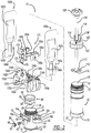
- the device 10 includes a housing having a first housing portion 12 and a second housing portion 14.
- the first housing portion 12 includes a proximal end 16 and a distal end 18, which is opposite to the proximal end 16.
- a proximal coupling member 20 At the proximal end 16 is a proximal coupling member 20.
- the proximal coupling member 20 can be any suitable coupling member, such as external threads as illustrated.
- a distal end coupling member 22 is at the distal end 18.
- the distal end coupling member 22 can be any suitable coupling member, such as an internally threaded coupling member, as illustrated in Figure 5 for example.
- the first housing portion 12 defines a first mixing chamber portion 24 of the device 10.
- the second housing portion 14 includes a proximal end 30 and a distal end 32, which is opposite to the proximal end 30. At the proximal end 30 is a proximal coupling member 34.
- the proximal coupling member 34 can be any suitable coupling member, such as external threads as illustrated.
- the second housing portion 14 defines a second mixing chamber portion 36 of the device 10.
- the first and second mixing chamber portions 24 and 36 together define a mixing chamber of the device 10, which can include the powder component of bone cement.
- An outlet 38 of the second mixing chamber portion 36 is at the distal end 32 of the second housing portion 14.
- the second housing portion 14 is coupled to the first housing portion 12 through cooperation between the distal end coupling member 22 of the first housing portion 12 and the proximal coupling member 34 of the second housing portion 14, as illustrated in Figure 5 , for example.
- the second housing portion 14 includes a first radially extending piercing cannula 40 extending therefrom.
- the first piercing cannula 40 is in cooperation with the second mixing chamber portion 36.
- the first piercing cannula 40 includes a pointed distal tip configured to pierce and penetrate a container including a liquid bone cement component as described herein to permit the liquid bone cement to be extracted therefrom as described herein.
- the first piercing cannula 40 is surrounded by a first cannula housing 42 extending from the second housing portion 14.
- a second piercing cannula 44 extends from the second housing portion 14 in a direction opposite to the first piercing cannula 40.
- the second piercing cannula 44 is surrounded by a second cannula housing 46.
- the second piercing cannula 44 is similar to the first piercing cannula 40, and the second cannula housing 46 is similar to the first cannula housing 42.
- the first piercing cannula 40 and the second piercing cannula 44 are generally on opposite sides of the second housing portion 14 and extend perpendicular to a longitudinal axis of the housing 42.
- the second piercing cannula 44 is optional and need not be included.
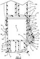
- An indicator housing 50 extends radially from the second housing portion 14. Seated within the indicator housing 50 is a spring 52 and a vacuum indicator, which can be a piston 54 for example, as illustrated.
- the piston 54 includes a body 56 with an outer surface 58.
- the body 56 defines an inner cavity 60, which the spring 52 is seated within (see Figure 5 ).
- the spring 52 also abuts an outer surface 62 of the second housing portion 14 surrounded by the indicator housing 50.
- the indicator housing 50 is in communication with the second mixing chamber portion 36 by way of a passageway 64 defined by the outer surface 62 and extending to the second mixing chamber portion 36.
- a washer or any suitable seal 66 surrounds the body 56.
- the spring 52 biases the piston 54 in the outward or first configuration of Figure 5 .
- the piston 54 is movable to a second or retracted position in response to pressure of the first and second mixing chamber portions 24 and 36 being reduced below a predetermined threshold, as illustrated in Figure 7 for example.
- the outer surface 58 of the piston 54 extends out from within the indicator housing 50.
- the outer surface 58 is recessed within the indicator housing.
- the second housing portion 14 further includes a first retention member 70 and a second retention member 72.
- the first and second retention members 70 and 72 are generally on opposite sides of the second housing portion 14.
- the first and second piercing cannulas 40 and 44 are between the first and second retention members 70 and 72.
- the first retention member 70 includes a proximal rail 74a and a distal rail 76a.
- the proximal and distal rails 74a and 76a extend generally spaced apart and parallel to one another.
- the second retention member 72 is substantially similar to the first retention member 70, and thus includes a proximal rail 74b and a distal rail 76b.
- the proximal rail 74b and the distal rail 76b extend generally parallel to one another and are spaced apart.
- An insert for the second housing portion 14 is illustrated at reference numeral 80. Extending from an outer periphery of the insert 80 is a proximal rim 84, an intermediate rim 86, and a distal rim 88. A plurality of spaced apart locking flanges 90 extend from the insert 80 proximate to the distal rim 88. As illustrated in Figure 5 , the insert 80 is seated within the second housing portion 14 at the distal end 32 thereof such that the distal rim 88 is seated on an inner distal flange 92 defined at an interior of the second housing portion 14 to support the insert 80 therein. The locking flanges 90 couple with corresponding recesses 94 of the second housing portion 14 to secure the insert 80 at the distal end 32 of the second housing portion 14.
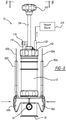
- the device 10 further includes a cap 102 and a plunger rod 104 extending through a plunger aperture 106 defined by the cap 102.
- a handle 108 At a first end of the plunger rod 104 is a handle 108, and at a second end of the plunger rod 104 opposite to the handle 108 is a mixer 110.
- the mixer 110 includes a center portion 112 to which the plunger rod 104 is mounted. Extending from the plunger rod 104 is a plurality of spaced apart mixing fins 114.
- the cap 102 defines a first port 116, which is illustrated as covered by cap 118, and a second port 120. Contents of the first and second housing portions 12 and 14 can be extracted through the first port 116 after removal of the cap 118.
- the second port 120 can be connected to a vacuum source, such as the vacuum source 210 described herein, with any suitable connector, such as connection tube 212.
- a vacuum source such as the vacuum source 210 described herein
- any suitable connector such as connection tube 212.
- Threads 122 Figure 9 , for example
- the threads 122 can be any suitable coupling member to connect the cap 102 to the first housing portion 12.
- first container support 130a Coupled to the first and second retention members 70 and 72 is a first container support 130a and a second container support 130b.
- the second container support 130b is optional and need not be included.
- the first container support 130a includes a first flange 132a and a second flange 134a.
- the first container support 130a defines a first slot 136a and a first cannula receptacle 138a configured to receive the first piercing cannula 40 therein.
- a first outer surface 140a of the first container support 130a is opposite to a first inner surface 142a.
- the first slot 136a is between the first outer surface 140a and the first inner surface 142a.
- first cannula boss 144a Extending from the first inner surface 142a is a first cannula boss 144a, which surrounds the first cannula receptacle 138a.
- the first cannula receptacle 138a extends through the first inner surface 142a to provide a passageway to the first slot 136a.
- the first cannula boss 144a is sized and shaped to receive the first cannula housing 42 therein.
- the second container support 130b is substantially similar to the first container support 130a. Therefore, the description of the first container support 130a also applies to the second container support 130b.
- Features in common between the first and second container supports 130a and 130b are referenced in the figures with respect to second container support 130b using the same reference numbers, but with the letter "b" instead of the letter "a.”
- first flange 132a is slidably coupled to the first retention member 70 and the second flange 134a is slidably coupled to the second retention member 72.
- first flange 132b is slidably coupled to the first retention member 70 and the second flange 134b is slidably coupled to the second retention member 72.
- a first container 160a is seated within the first slot 136a of the first container support 130a.
- the first container 160a defines a receptacle 162a configured to store a liquid component of bone cement therein.
- the first container 160a defines a tapered portion 164a and retention members 166a.
- a tapered portion 164a is seated within the first slot 136a, and secured therein through cooperation between retention members 166a and corresponding retention members within the first slot 136a.
- the first container 160a can be any suitable container for storing the liquid component of bone cement therein, such as a flexible polymeric container.
- a second container 160b is substantially similar to the first container 160a.
- the second container 160b is optional and need not be included, such as when the second container support 130b is not included.
- Features of the second container 160b are identified in the drawings with in the same reference numbers used to identify features in common with the first container 160a, but include the letter "b" instead of the letter "a.”
- the second container 160b is seated within the second slot 136b defined by the second container support 130b.
- a safety insert for the device 10 is illustrated at reference number 170.
- the safety insert 170 includes a main body 172 and a flange 174 extending therefrom.
- the flange 174 defines an aperture 176, which is sized and shaped to receive the piston 54 therein.
- a tab 178 extends from an end of the main body 172 opposite to the flange 174.
- the tab 178 can be configured in any suitable manner to facilitate removal of the safety insert 170 from cooperation with the first and second housing portions 12 and 14 as described herein.
- Extending from opposite ends of the main body 172 are a first arm 180a and a second arm 180b.
- the first and second arms 180a and 180b extend from the same side of the main body 172.
- the first arm 180a includes a first stop 184a, which extends from the first arm 180a in the same direction that the flange 174 does, and defines an aperture 186a.
- the second arm 180b includes a similar second stop 184b and aperture 186b.
- the piston 54 In the first position, the piston 54 is arranged such that a portion of the body 56 adjacent to the outer surface 58 extends through the aperture 176 defined by the flange 174 of the safety insert 170, as illustrated in Figure 5 . With the piston 54 arranged in this first position, the safety insert 170 cannot be removed from cooperation with the first and second housing portions 12 and 14, as illustrated in Figures 1 and 5 for example.
- the safety insert 170 is further coupled to the second housing portion 14 through cooperation with the proximal rail 74a and the distal rail 76a of the first retention member 70, as illustrated in Figure 5 for example.
- proximal rail 74a is seated within a proximal recess 188a of the main body 172 at the safety insert 170, and the distal rail 76a is seated within distal recess 188b of the main body 172.
- the first and second container supports 130a and 130b are retained in the expanded or deactivated position of Figure 1 . More specifically, the first arm 180a of the safety insert 170 is positioned between the first container support 130a and the second housing portion 14 with the first stop 184a arranged such that the first cannula housing 42 is seated within the aperture 186a. Similarly, the second arm 180b is arranged between the second container support 130b and the second housing portion 14 such that the second cannula housing 46 is seated within the second aperture 186b.
- the first piercing cannula 40 pierces and penetrates the liquid component receptacle 162a as the first container 160a is pushed onto the first piercing cannula 40 in response to movement of the first container support 130a to the active position of Figures 8 and 9 .
- the second piercing cannula 44 pierces and penetrates the liquid component receptacle 162b of the second container 160b when the second container support 130b is moved to the activated position of Figures 8 and 9 .
- the liquid component of bone cement stored within the liquid component receptacles 162a and 162b is drawn out from within the liquid component receptacles 162a and 162b through the first and second piercing cannulas 40 and 44 respectively and into the second mixing chamber portion 36, where the liquid component of bone cement mixes with the powder component of bone cement stored therein.
- the mixer 110 can be rotated and/or moved longitudinally through the first and second mixing chamber portions 24 and 36 using the handle 108 coupled to the plunger rod 104. After the liquid and powder bone cement components have been sufficiently mixed, they can be extracted out from within the first and second mixing chamber portions 24 and 36 through the first port 116 for delivery to a desired area.
- the present teachings therefore provide a device and method to ensure that surgical staff mixes the bone cement under the proper vacuum, which ensures that the mixed bone cement does not include excessive amounts of air therein. For example, if the air pressure within the first and second mixing chamber portions 24 and 36 is not at or lower than the predetermined threshold, the piston 54 will not move to the second position, and thus will prevent removal of the safety insert 170 from cooperation with the second housing portion 14 in which the first and second arms 180a and 180b prevent movement of the first and second container supports 130a and 130b together to the activated position of Figures 8 and 9 .
- the spring 52 of the piston 54 will force the piston back outward to the first position, which will give the operator a visual indicator that the pressure is no longer at or below the predetermined threshold.
- the piston 54 need not include the spring 52, and thus the piston 54 can be retained in the first position by a friction fit with an interior of the indicator housing 50.
- the washer or seal 66 can enhance the friction fit with the indicator housing 50.
Landscapes
- Health & Medical Sciences (AREA)
- Chemical Kinetics & Catalysis (AREA)
- Chemical & Material Sciences (AREA)
- Orthopedic Medicine & Surgery (AREA)
- Surgery (AREA)
- Life Sciences & Earth Sciences (AREA)
- Medical Informatics (AREA)
- Heart & Thoracic Surgery (AREA)
- Biomedical Technology (AREA)
- Molecular Biology (AREA)
- Animal Behavior & Ethology (AREA)
- General Health & Medical Sciences (AREA)
- Public Health (AREA)
- Veterinary Medicine (AREA)
- Engineering & Computer Science (AREA)
- Nuclear Medicine, Radiotherapy & Molecular Imaging (AREA)
- Surgical Instruments (AREA)
- Dental Tools And Instruments Or Auxiliary Dental Instruments (AREA)
Claims (14)
- Dispositif (10) de stockage et mélange de composants de ciment d'os comprenant :un boîtier (12, 14) définissant une chambre de mélange (24, 36) configurée pour stocker un premier composant de ciment d'os dans celle-ci ;un dispositif de sécurité (170) mobile entre une première position de sécurité et une deuxième position de sécurité, dans la première position de sécurité, le dispositif de sécurité restreint un contact entre le premier composant de ciment d'os et un deuxième composant de ciment d'os dans la chambre de mélange, dans la deuxième position de sécurité, le dispositif de sécurité permet un contact entre les premier et deuxième composants de ciment d'os dans la chambre de mélange ;caractérisé en ce qu'il comprend en outre :
un indicateur de vide (54) configuré pour se déplacer depuis une première position d'indicateur de vide vers une deuxième position d'indicateur de vide quand une pression à l'intérieur de la chambre de mélange baisse sous une valeur de seuil, dans lequel :l'indicateur de vide restreint le déplacement du dispositif de sécurité (170) depuis la première position de sécurité vers la deuxième position de sécurité quand il est dans la première position d'indicateur de vide ; etl'indicateur de vide permet le déplacement du dispositif de sécurité (170) depuis la première position de sécurité vers la deuxième position de sécurité quand il est dans la deuxième position d'indicateur de vide. - Dispositif selon la revendication 1, comprenant en outre :une première canule de perçage (40) en communication avec la chambre de mélange (24, 36) ; etun premier conteneur (160a) fixé au boîtier, le premier conteneur configuré pour stocker le deuxième composant de ciment d'os dans celui-ci, dans lequel quand le dispositif de sécurité est dans la deuxième position de sécurité, le premier conteneur est mobile depuis une première position de conteneur dans laquelle la première canule de perçage ne pénètre pas le premier conteneur vers une deuxième position de conteneur dans laquelle la première canule de perçage pénètre le premier conteneur pour permettre au deuxième composant de ciment d'os de se déplacer dans la chambre de mélange pour se mélanger au premier composant de ciment d'os.
- Dispositif selon la revendication 1, dans lequel le premier composant de ciment d'os inclut un composant en poudre et le deuxième composant de ciment d'os inclut un composant liquide.
- Dispositif selon la revendication 2, dans lequel premier conteneur (160a) est fixé au boîtier avec un premier élément de support de conteneur (130a) couplé de manière coulissante au boîtier.
- Dispositif selon la revendication 4, comprenant en outre une deuxième canule de perçage (44), la première canule de perçage et la deuxième canule de perçage s'étendent depuis des côtés opposés du boîtier.
- Dispositif selon la revendication 5, comprenant en outre un deuxième conteneur (160b) fixé au boîtier avec un deuxième élément de support (130b) couplé de manière coulissante au boîtier, dans lequel le deuxième conteneur est configuré pour stocker le deuxième composant de ciment d'os dans celui-ci.
- Dispositif selon la revendication 1, dans lequel le dispositif de sécurité (170) inclut un premier bras (180a) et un deuxième bras (180b) espacé du premier bras pour recevoir le boîtier entre les deux.
- Dispositif selon la revendication 1, dans lequel le dispositif de sécurité (170) inclut une bride (174) définissant une ouverture (176) configurée pour recevoir l'indicateur de vide (54) dans celle-ci.
- Dispositif selon la revendication 8, dans lequel l'indicateur de vide (54) est assis à l'intérieur de l'ouverture (176) dans la première position d'indicateur vide, et espacé de l'ouverture dans la deuxième position d'indicateur de vide.
- Dispositif selon la revendication 1, dans lequel l'indicateur de vide (54) inclut un piston.
- Dispositif selon la revendication 1, dans lequel l'indicateur de vide (54) est assis à l'intérieur d'un boîtier d'indicateur (50) qui est en communication fluide avec la chambre de mélange (24, 36) de sorte que quand une pression à l'intérieur de la chambre de mélange baisse sous la valeur de seuil, l'indicateur de vide soit aspiré vers l'intérieur en direction de la chambre de mélange jusqu'à la deuxième position d'indicateur de vide.
- Dispositif selon la revendication 11, dans lequel l'indicateur de vide (54) inclut un piston rappelé dans la première position d'indicateur de vide avec un ressort (52).
- Dispositif selon la revendication 11, dans lequel l'indicateur de vide (54) est retenu au niveau de la première position d'indicateur de vide par ajustement par friction quand la pression à l'intérieur de la chambre de mélange est au-dessus de la valeur de seuil.
- Dispositif selon la revendication 4, dans lequel le premier élément support de conteneur (130a) est fixé de manière coulissante à l'extérieur du boîtier et mobile depuis une première position vers une deuxième position dans laquelle le premier élément support de conteneur est plus proche du boîtier que dans la première position.
Applications Claiming Priority (2)
| Application Number | Priority Date | Filing Date | Title |
|---|---|---|---|
| US14/050,983 US9549770B2 (en) | 2013-10-10 | 2013-10-10 | Vacuum indicator system that avoid release without the proper vacuum level |
| PCT/IB2014/065224 WO2015052692A1 (fr) | 2013-10-10 | 2014-10-10 | Système indicateur de vide qui évite la libération en l'absence d'un niveau de vide approprié |
Publications (2)
| Publication Number | Publication Date |
|---|---|
| EP3054880A1 EP3054880A1 (fr) | 2016-08-17 |
| EP3054880B1 true EP3054880B1 (fr) | 2020-01-01 |
Family
ID=51868996
Family Applications (1)
| Application Number | Title | Priority Date | Filing Date |
|---|---|---|---|
| EP14795869.8A Active EP3054880B1 (fr) | 2013-10-10 | 2014-10-10 | Système indicateur de vide qui évite la libération en l'absence d'un niveau de vide approprié |
Country Status (3)
| Country | Link |
|---|---|
| US (3) | US9549770B2 (fr) |
| EP (1) | EP3054880B1 (fr) |
| WO (1) | WO2015052692A1 (fr) |
Cited By (10)
| Publication number | Priority date | Publication date | Assignee | Title |
|---|---|---|---|---|
| EP4385613A1 (fr) | 2022-12-13 | 2024-06-19 | Heraeus Medical GmbH | Dispositif pour mélanger du ciment osseux |
| EP4474338A1 (fr) | 2023-06-06 | 2024-12-11 | Heraeus Medical GmbH | Ouvre-ampoules avec piston multifonctionnel |
| EP4474042A1 (fr) | 2023-06-06 | 2024-12-11 | Heraeus Medical GmbH | Système de mélange avec brise-ampoule latéral |
| EP4545027A1 (fr) | 2023-10-26 | 2025-04-30 | Heraeus Medical GmbH | Dispositif pour exprimer du ciment osseux, utilisation et système |
| EP4566701A1 (fr) | 2023-12-07 | 2025-06-11 | Heraeus Medical GmbH | Kit pour la préparation et l'extraction de ciment osseux et procédé |
| EP4603176A1 (fr) | 2024-02-15 | 2025-08-20 | Heraeus Medical GmbH | Système de mélange de ciment osseux avec transfert de fluide monomère amélioré |
| EP4616935A1 (fr) | 2024-03-15 | 2025-09-17 | Heraeus Medical GmbH | Système de mélange de ciment osseux avec liaison par piqûre |
| EP4616938A1 (fr) | 2024-03-15 | 2025-09-17 | Heraeus Medical GmbH | Système de mélange de ciment osseux comprenant un composé de perçage et une fonction de pompage |
| EP4616936A1 (fr) | 2024-03-15 | 2025-09-17 | Heraeus Medical GmbH | Système de mélange de ciment osseux comprenant un composé de perçage et un piston multifonctionnel |
| EP4616937A1 (fr) | 2024-03-15 | 2025-09-17 | Heraeus Medical GmbH | Système de mélange de ciment osseux avec connexion à insertion et fonctionnement multifonction |
Families Citing this family (6)
| Publication number | Priority date | Publication date | Assignee | Title |
|---|---|---|---|---|
| US9549770B2 (en) | 2013-10-10 | 2017-01-24 | Biomet Sas | Vacuum indicator system that avoid release without the proper vacuum level |
| US10905485B2 (en) * | 2016-07-27 | 2021-02-02 | Zimmer Biomet France Sas | Apparatus for mixing bone cement |
| US10856923B2 (en) | 2018-01-22 | 2020-12-08 | Warsaw Orthopedic, Inc. | Manual mixer |
| US11229467B2 (en) | 2018-04-11 | 2022-01-25 | Zimmer Gmbh | Valve for prefilled bone cement mixing system |
| US11623192B2 (en) | 2018-08-21 | 2023-04-11 | Zimmer Gmbh | Autonomous vacuum pump |
| CN112473488A (zh) * | 2020-11-22 | 2021-03-12 | 郑州工程技术学院 | 一种化工材料生产用原料溶解装置 |
Family Cites Families (20)
| Publication number | Priority date | Publication date | Assignee | Title |
|---|---|---|---|---|
| US4019629A (en) | 1975-02-13 | 1977-04-26 | Dubner Robert B | Pressurized tennis ball container |
| US4178932A (en) | 1977-09-06 | 1979-12-18 | Ryder International Corporation | Vacuum curettage device with vacuum indicator |
| US4222276A (en) | 1978-11-02 | 1980-09-16 | Derogatis Ronald A | Vacuum packing apparatus |
| US5395167A (en) | 1993-11-16 | 1995-03-07 | Murray; William M. | Manual bone cement mixing system |
| US5549381A (en) | 1995-05-19 | 1996-08-27 | Hays; Greta J. | Method and apparatus for mixing polymeric bone cement components |
| US5624184A (en) | 1995-10-10 | 1997-04-29 | Chan; Kwan-Ho | Bone cement preparation kit having a breakable mixing shaft forming an output port |
| US5788463A (en) | 1995-12-22 | 1998-08-04 | Chan; Kwan-Ho | Manual vacuum producing system having pressure indicator |
| US5797680A (en) | 1996-09-05 | 1998-08-25 | Murray; William M. | Manual bone cement mixing system with vacuum pump start-stop device |
| US5803282A (en) | 1996-12-13 | 1998-09-08 | Chen; Pao Ting | Vacuum indicator for a bottle |
| US6042262A (en) | 1997-07-29 | 2000-03-28 | Stryker Technologies Corportion | Apparatus for storing, mixing, and dispensing two-component bone cement |
| US5934803A (en) | 1997-10-30 | 1999-08-10 | Physical Systems, Inc. | Apparatus and method for mixing multi-part reaction materials under vacuum |
| US6120174A (en) * | 1999-01-14 | 2000-09-19 | Bristol-Myers Squibb | Apparatus and method for mixing and dispensing bone cement |
| US6116773A (en) | 1999-01-22 | 2000-09-12 | Murray; William M. | Bone cement mixer and method |
| SE530710C2 (sv) * | 2005-07-05 | 2008-08-19 | Biomet Cementing Technologies | Förfarande och anordning för att bringa en pulver- och en vätskekomponent, företrädesvis polymer och monomer, i kontakt med varandra för att blanda dessa, företrädesvis till bencement |
| US8480289B2 (en) | 2008-08-22 | 2013-07-09 | Biomet Manufacturing, Llc | Bone cement mixing cartridge and method of use |
| GB201014514D0 (en) | 2010-09-01 | 2010-10-13 | Biocomposites Ltd | Mixing and dispensing apparatus for bone void filler |
| ITMI20111798A1 (it) | 2011-10-04 | 2013-04-05 | G21 S R L | Apparecchiatura e procedimento di preparazione di cementi ossei |
| US9549770B2 (en) | 2013-10-10 | 2017-01-24 | Biomet Sas | Vacuum indicator system that avoid release without the proper vacuum level |
| DE102014112042B4 (de) * | 2014-08-22 | 2017-11-23 | Heraeus Medical Gmbh | Austragsvorrichtung mit elastisch angetriebenem Mischer |
| DE102014112043A1 (de) * | 2014-08-22 | 2016-02-25 | Heraeus Medical Gmbh | Gespannte Öffnungsvorrichtung für Monomerbehälter |
-
2013
- 2013-10-10 US US14/050,983 patent/US9549770B2/en active Active
-
2014
- 2014-10-10 EP EP14795869.8A patent/EP3054880B1/fr active Active
- 2014-10-10 WO PCT/IB2014/065224 patent/WO2015052692A1/fr not_active Ceased
-
2016
- 2016-12-07 US US15/371,592 patent/US9724661B2/en active Active
-
2017
- 2017-08-07 US US15/670,476 patent/US9889415B2/en active Active
Non-Patent Citations (1)
| Title |
|---|
| None * |
Cited By (12)
| Publication number | Priority date | Publication date | Assignee | Title |
|---|---|---|---|---|
| EP4385613A1 (fr) | 2022-12-13 | 2024-06-19 | Heraeus Medical GmbH | Dispositif pour mélanger du ciment osseux |
| EP4474338A1 (fr) | 2023-06-06 | 2024-12-11 | Heraeus Medical GmbH | Ouvre-ampoules avec piston multifonctionnel |
| EP4474042A1 (fr) | 2023-06-06 | 2024-12-11 | Heraeus Medical GmbH | Système de mélange avec brise-ampoule latéral |
| EP4545027A1 (fr) | 2023-10-26 | 2025-04-30 | Heraeus Medical GmbH | Dispositif pour exprimer du ciment osseux, utilisation et système |
| US12599423B2 (en) | 2023-10-26 | 2026-04-14 | Heraeus Medical Gmbh | Apparatus for pressing out bone cement, use and system |
| EP4566701A1 (fr) | 2023-12-07 | 2025-06-11 | Heraeus Medical GmbH | Kit pour la préparation et l'extraction de ciment osseux et procédé |
| EP4603176A1 (fr) | 2024-02-15 | 2025-08-20 | Heraeus Medical GmbH | Système de mélange de ciment osseux avec transfert de fluide monomère amélioré |
| WO2025172114A1 (fr) | 2024-02-15 | 2025-08-21 | Heraeus Medical Gmbh | Système de mélange de ciment osseux à transfert de liquide monomère amélioré |
| EP4616935A1 (fr) | 2024-03-15 | 2025-09-17 | Heraeus Medical GmbH | Système de mélange de ciment osseux avec liaison par piqûre |
| EP4616938A1 (fr) | 2024-03-15 | 2025-09-17 | Heraeus Medical GmbH | Système de mélange de ciment osseux comprenant un composé de perçage et une fonction de pompage |
| EP4616936A1 (fr) | 2024-03-15 | 2025-09-17 | Heraeus Medical GmbH | Système de mélange de ciment osseux comprenant un composé de perçage et un piston multifonctionnel |
| EP4616937A1 (fr) | 2024-03-15 | 2025-09-17 | Heraeus Medical GmbH | Système de mélange de ciment osseux avec connexion à insertion et fonctionnement multifonction |
Also Published As
| Publication number | Publication date |
|---|---|
| US9724661B2 (en) | 2017-08-08 |
| US9549770B2 (en) | 2017-01-24 |
| WO2015052692A1 (fr) | 2015-04-16 |
| US9889415B2 (en) | 2018-02-13 |
| US20150103616A1 (en) | 2015-04-16 |
| EP3054880A1 (fr) | 2016-08-17 |
| US20170341042A1 (en) | 2017-11-30 |
| US20170080396A1 (en) | 2017-03-23 |
Similar Documents
| Publication | Publication Date | Title |
|---|---|---|
| US9889415B2 (en) | Vacuum indicator system that avoid release without the proper vacuum level | |
| CN102905654B (zh) | 用于眼科手术过程的注液管的眼科手术套件 | |
| US6551299B2 (en) | Adapter for mixing and injection of preparations | |
| US9545464B2 (en) | Syringe with ratcheting operating rod and lockable plunger head | |
| CN101180013B (zh) | 用于存储和交付两相合成物的药筒 | |
| US9907728B2 (en) | Fluid management devices and methods | |
| EP3131473B1 (fr) | Buse de mélange | |
| US20150265500A1 (en) | Vial adapters | |
| EP2538995B1 (fr) | Système d'administration sans danger de médicament | |
| AU2021209845B2 (en) | Vial adapter device | |
| JP2014121520A (ja) | ペースト状の塊を混合し、分配するための装置 | |
| CN108883258B (zh) | 用于将塞递送到空隙的医疗装置 | |
| EP2863810B1 (fr) | Dispositif de mélange et de distribution de bioadhésif | |
| CN110312541B (zh) | 带有塞子引导件的注射器和柱塞杆 | |
| EP2701599B1 (fr) | Dispositif de manipulation de fluide équipé d'un mécanisme à ressort | |
| WO2019183057A1 (fr) | Tige de piston pour seringues sous-remplies | |
| US20130105018A1 (en) | Turbulence-inducing mixing device | |
| CN223403880U (zh) | 脊椎内镜下骨面止血装置 | |
| CA3164499C (fr) | Dispositif adaptateur de flacon | |
| EP4299169B1 (fr) | Dispositif et procédé de fourniture de la pâte de ciment osseux | |
| JP2002345789A (ja) | アダプタ |
Legal Events
| Date | Code | Title | Description |
|---|---|---|---|
| PUAI | Public reference made under article 153(3) epc to a published international application that has entered the european phase |
Free format text: ORIGINAL CODE: 0009012 |
|
| 17P | Request for examination filed |
Effective date: 20160510 |
|
| AK | Designated contracting states |
Kind code of ref document: A1 Designated state(s): AL AT BE BG CH CY CZ DE DK EE ES FI FR GB GR HR HU IE IS IT LI LT LU LV MC MK MT NL NO PL PT RO RS SE SI SK SM TR |
|
| AX | Request for extension of the european patent |
Extension state: BA ME |
|
| DAX | Request for extension of the european patent (deleted) | ||
| STAA | Information on the status of an ep patent application or granted ep patent |
Free format text: STATUS: EXAMINATION IS IN PROGRESS |
|
| 17Q | First examination report despatched |
Effective date: 20180913 |
|
| RIC1 | Information provided on ipc code assigned before grant |
Ipc: B01F 13/04 20060101ALI20190523BHEP Ipc: B01F 13/06 20060101ALI20190523BHEP Ipc: B01F 15/00 20060101ALI20190523BHEP Ipc: B01F 11/00 20060101ALI20190523BHEP Ipc: A61B 17/88 20060101AFI20190523BHEP Ipc: B01F 13/00 20060101ALI20190523BHEP Ipc: B01F 15/02 20060101ALI20190523BHEP |
|
| GRAP | Despatch of communication of intention to grant a patent |
Free format text: ORIGINAL CODE: EPIDOSNIGR1 |
|
| STAA | Information on the status of an ep patent application or granted ep patent |
Free format text: STATUS: GRANT OF PATENT IS INTENDED |
|
| INTG | Intention to grant announced |
Effective date: 20190705 |
|
| GRAS | Grant fee paid |
Free format text: ORIGINAL CODE: EPIDOSNIGR3 |
|
| GRAA | (expected) grant |
Free format text: ORIGINAL CODE: 0009210 |
|
| STAA | Information on the status of an ep patent application or granted ep patent |
Free format text: STATUS: THE PATENT HAS BEEN GRANTED |
|
| AK | Designated contracting states |
Kind code of ref document: B1 Designated state(s): AL AT BE BG CH CY CZ DE DK EE ES FI FR GB GR HR HU IE IS IT LI LT LU LV MC MK MT NL NO PL PT RO RS SE SI SK SM TR |
|
| REG | Reference to a national code |
Ref country code: GB Ref legal event code: FG4D |
|
| REG | Reference to a national code |
Ref country code: CH Ref legal event code: EP Ref country code: CH Ref legal event code: NV Representative=s name: MICHELI AND CIE SA, CH Ref country code: AT Ref legal event code: REF Ref document number: 1218813 Country of ref document: AT Kind code of ref document: T Effective date: 20200115 |
|
| REG | Reference to a national code |
Ref country code: IE Ref legal event code: FG4D |
|
| REG | Reference to a national code |
Ref country code: DE Ref legal event code: R096 Ref document number: 602014059380 Country of ref document: DE |
|
| REG | Reference to a national code |
Ref country code: NL Ref legal event code: MP Effective date: 20200101 |
|
| REG | Reference to a national code |
Ref country code: LT Ref legal event code: MG4D |
|
| PG25 | Lapsed in a contracting state [announced via postgrant information from national office to epo] |
Ref country code: FI Free format text: LAPSE BECAUSE OF FAILURE TO SUBMIT A TRANSLATION OF THE DESCRIPTION OR TO PAY THE FEE WITHIN THE PRESCRIBED TIME-LIMIT Effective date: 20200101 Ref country code: RS Free format text: LAPSE BECAUSE OF FAILURE TO SUBMIT A TRANSLATION OF THE DESCRIPTION OR TO PAY THE FEE WITHIN THE PRESCRIBED TIME-LIMIT Effective date: 20200101 Ref country code: NO Free format text: LAPSE BECAUSE OF FAILURE TO SUBMIT A TRANSLATION OF THE DESCRIPTION OR TO PAY THE FEE WITHIN THE PRESCRIBED TIME-LIMIT Effective date: 20200401 Ref country code: PT Free format text: LAPSE BECAUSE OF FAILURE TO SUBMIT A TRANSLATION OF THE DESCRIPTION OR TO PAY THE FEE WITHIN THE PRESCRIBED TIME-LIMIT Effective date: 20200527 Ref country code: CZ Free format text: LAPSE BECAUSE OF FAILURE TO SUBMIT A TRANSLATION OF THE DESCRIPTION OR TO PAY THE FEE WITHIN THE PRESCRIBED TIME-LIMIT Effective date: 20200101 Ref country code: NL Free format text: LAPSE BECAUSE OF FAILURE TO SUBMIT A TRANSLATION OF THE DESCRIPTION OR TO PAY THE FEE WITHIN THE PRESCRIBED TIME-LIMIT Effective date: 20200101 Ref country code: LT Free format text: LAPSE BECAUSE OF FAILURE TO SUBMIT A TRANSLATION OF THE DESCRIPTION OR TO PAY THE FEE WITHIN THE PRESCRIBED TIME-LIMIT Effective date: 20200101 |
|
| PG25 | Lapsed in a contracting state [announced via postgrant information from national office to epo] |
Ref country code: IS Free format text: LAPSE BECAUSE OF FAILURE TO SUBMIT A TRANSLATION OF THE DESCRIPTION OR TO PAY THE FEE WITHIN THE PRESCRIBED TIME-LIMIT Effective date: 20200501 Ref country code: BG Free format text: LAPSE BECAUSE OF FAILURE TO SUBMIT A TRANSLATION OF THE DESCRIPTION OR TO PAY THE FEE WITHIN THE PRESCRIBED TIME-LIMIT Effective date: 20200401 Ref country code: HR Free format text: LAPSE BECAUSE OF FAILURE TO SUBMIT A TRANSLATION OF THE DESCRIPTION OR TO PAY THE FEE WITHIN THE PRESCRIBED TIME-LIMIT Effective date: 20200101 Ref country code: GR Free format text: LAPSE BECAUSE OF FAILURE TO SUBMIT A TRANSLATION OF THE DESCRIPTION OR TO PAY THE FEE WITHIN THE PRESCRIBED TIME-LIMIT Effective date: 20200402 Ref country code: SE Free format text: LAPSE BECAUSE OF FAILURE TO SUBMIT A TRANSLATION OF THE DESCRIPTION OR TO PAY THE FEE WITHIN THE PRESCRIBED TIME-LIMIT Effective date: 20200101 Ref country code: LV Free format text: LAPSE BECAUSE OF FAILURE TO SUBMIT A TRANSLATION OF THE DESCRIPTION OR TO PAY THE FEE WITHIN THE PRESCRIBED TIME-LIMIT Effective date: 20200101 |
|
| REG | Reference to a national code |
Ref country code: DE Ref legal event code: R097 Ref document number: 602014059380 Country of ref document: DE |
|
| REG | Reference to a national code |
Ref country code: DE Ref legal event code: R082 Ref document number: 602014059380 Country of ref document: DE Representative=s name: VENNER SHIPLEY GERMANY LLP, DE Ref country code: DE Ref legal event code: R082 Ref document number: 602014059380 Country of ref document: DE Representative=s name: VENNER SHIPLEY LLP, DE |
|
| PG25 | Lapsed in a contracting state [announced via postgrant information from national office to epo] |
Ref country code: EE Free format text: LAPSE BECAUSE OF FAILURE TO SUBMIT A TRANSLATION OF THE DESCRIPTION OR TO PAY THE FEE WITHIN THE PRESCRIBED TIME-LIMIT Effective date: 20200101 Ref country code: SM Free format text: LAPSE BECAUSE OF FAILURE TO SUBMIT A TRANSLATION OF THE DESCRIPTION OR TO PAY THE FEE WITHIN THE PRESCRIBED TIME-LIMIT Effective date: 20200101 Ref country code: DK Free format text: LAPSE BECAUSE OF FAILURE TO SUBMIT A TRANSLATION OF THE DESCRIPTION OR TO PAY THE FEE WITHIN THE PRESCRIBED TIME-LIMIT Effective date: 20200101 Ref country code: SK Free format text: LAPSE BECAUSE OF FAILURE TO SUBMIT A TRANSLATION OF THE DESCRIPTION OR TO PAY THE FEE WITHIN THE PRESCRIBED TIME-LIMIT Effective date: 20200101 Ref country code: ES Free format text: LAPSE BECAUSE OF FAILURE TO SUBMIT A TRANSLATION OF THE DESCRIPTION OR TO PAY THE FEE WITHIN THE PRESCRIBED TIME-LIMIT Effective date: 20200101 Ref country code: RO Free format text: LAPSE BECAUSE OF FAILURE TO SUBMIT A TRANSLATION OF THE DESCRIPTION OR TO PAY THE FEE WITHIN THE PRESCRIBED TIME-LIMIT Effective date: 20200101 |
|
| PLBE | No opposition filed within time limit |
Free format text: ORIGINAL CODE: 0009261 |
|
| STAA | Information on the status of an ep patent application or granted ep patent |
Free format text: STATUS: NO OPPOSITION FILED WITHIN TIME LIMIT |
|
| REG | Reference to a national code |
Ref country code: AT Ref legal event code: MK05 Ref document number: 1218813 Country of ref document: AT Kind code of ref document: T Effective date: 20200101 |
|
| 26N | No opposition filed |
Effective date: 20201002 |
|
| PG25 | Lapsed in a contracting state [announced via postgrant information from national office to epo] |
Ref country code: IT Free format text: LAPSE BECAUSE OF FAILURE TO SUBMIT A TRANSLATION OF THE DESCRIPTION OR TO PAY THE FEE WITHIN THE PRESCRIBED TIME-LIMIT Effective date: 20200101 Ref country code: AT Free format text: LAPSE BECAUSE OF FAILURE TO SUBMIT A TRANSLATION OF THE DESCRIPTION OR TO PAY THE FEE WITHIN THE PRESCRIBED TIME-LIMIT Effective date: 20200101 |
|
| PG25 | Lapsed in a contracting state [announced via postgrant information from national office to epo] |
Ref country code: SI Free format text: LAPSE BECAUSE OF FAILURE TO SUBMIT A TRANSLATION OF THE DESCRIPTION OR TO PAY THE FEE WITHIN THE PRESCRIBED TIME-LIMIT Effective date: 20200101 Ref country code: PL Free format text: LAPSE BECAUSE OF FAILURE TO SUBMIT A TRANSLATION OF THE DESCRIPTION OR TO PAY THE FEE WITHIN THE PRESCRIBED TIME-LIMIT Effective date: 20200101 |
|
| PG25 | Lapsed in a contracting state [announced via postgrant information from national office to epo] |
Ref country code: LU Free format text: LAPSE BECAUSE OF NON-PAYMENT OF DUE FEES Effective date: 20201010 Ref country code: MC Free format text: LAPSE BECAUSE OF FAILURE TO SUBMIT A TRANSLATION OF THE DESCRIPTION OR TO PAY THE FEE WITHIN THE PRESCRIBED TIME-LIMIT Effective date: 20200101 |
|
| REG | Reference to a national code |
Ref country code: BE Ref legal event code: MM Effective date: 20201031 |
|
| PG25 | Lapsed in a contracting state [announced via postgrant information from national office to epo] |
Ref country code: BE Free format text: LAPSE BECAUSE OF NON-PAYMENT OF DUE FEES Effective date: 20201031 |
|
| PG25 | Lapsed in a contracting state [announced via postgrant information from national office to epo] |
Ref country code: IE Free format text: LAPSE BECAUSE OF NON-PAYMENT OF DUE FEES Effective date: 20201010 |
|
| PG25 | Lapsed in a contracting state [announced via postgrant information from national office to epo] |
Ref country code: TR Free format text: LAPSE BECAUSE OF FAILURE TO SUBMIT A TRANSLATION OF THE DESCRIPTION OR TO PAY THE FEE WITHIN THE PRESCRIBED TIME-LIMIT Effective date: 20200101 Ref country code: MT Free format text: LAPSE BECAUSE OF FAILURE TO SUBMIT A TRANSLATION OF THE DESCRIPTION OR TO PAY THE FEE WITHIN THE PRESCRIBED TIME-LIMIT Effective date: 20200101 Ref country code: CY Free format text: LAPSE BECAUSE OF FAILURE TO SUBMIT A TRANSLATION OF THE DESCRIPTION OR TO PAY THE FEE WITHIN THE PRESCRIBED TIME-LIMIT Effective date: 20200101 |
|
| PG25 | Lapsed in a contracting state [announced via postgrant information from national office to epo] |
Ref country code: MK Free format text: LAPSE BECAUSE OF FAILURE TO SUBMIT A TRANSLATION OF THE DESCRIPTION OR TO PAY THE FEE WITHIN THE PRESCRIBED TIME-LIMIT Effective date: 20200101 Ref country code: AL Free format text: LAPSE BECAUSE OF FAILURE TO SUBMIT A TRANSLATION OF THE DESCRIPTION OR TO PAY THE FEE WITHIN THE PRESCRIBED TIME-LIMIT Effective date: 20200101 |
|
| P01 | Opt-out of the competence of the unified patent court (upc) registered |
Effective date: 20230527 |
|
| REG | Reference to a national code |
Ref country code: CH Ref legal event code: U11 Free format text: ST27 STATUS EVENT CODE: U-0-0-U10-U11 (AS PROVIDED BY THE NATIONAL OFFICE) Effective date: 20251101 |
|
| PGFP | Annual fee paid to national office [announced via postgrant information from national office to epo] |
Ref country code: DE Payment date: 20251010 Year of fee payment: 12 |
|
| PGFP | Annual fee paid to national office [announced via postgrant information from national office to epo] |
Ref country code: GB Payment date: 20251013 Year of fee payment: 12 |
|
| PGFP | Annual fee paid to national office [announced via postgrant information from national office to epo] |
Ref country code: FR Payment date: 20251014 Year of fee payment: 12 |
|
| PGFP | Annual fee paid to national office [announced via postgrant information from national office to epo] |
Ref country code: CH Payment date: 20251101 Year of fee payment: 12 |