EP4566701A1 - Kit pour la préparation et l'extraction de ciment osseux et procédé - Google Patents
Kit pour la préparation et l'extraction de ciment osseux et procédé Download PDFInfo
- Publication number
- EP4566701A1 EP4566701A1 EP23214789.2A EP23214789A EP4566701A1 EP 4566701 A1 EP4566701 A1 EP 4566701A1 EP 23214789 A EP23214789 A EP 23214789A EP 4566701 A1 EP4566701 A1 EP 4566701A1
- Authority
- EP
- European Patent Office
- Prior art keywords
- container
- kit
- bone cement
- squeezing
- component
- Prior art date
- Legal status (The legal status is an assumption and is not a legal conclusion. Google has not performed a legal analysis and makes no representation as to the accuracy of the status listed.)
- Pending
Links
Images




Classifications
-
- B—PERFORMING OPERATIONS; TRANSPORTING
- B01—PHYSICAL OR CHEMICAL PROCESSES OR APPARATUS IN GENERAL
- B01F—MIXING, e.g. DISSOLVING, EMULSIFYING OR DISPERSING
- B01F31/00—Mixers with shaking, oscillating, or vibrating mechanisms
- B01F31/40—Mixers with shaking, oscillating, or vibrating mechanisms with an axially oscillating rotary stirrer
-
- A—HUMAN NECESSITIES
- A61—MEDICAL OR VETERINARY SCIENCE; HYGIENE
- A61B—DIAGNOSIS; SURGERY; IDENTIFICATION
- A61B17/00—Surgical instruments, devices or methods
- A61B17/56—Surgical instruments or methods for treatment of bones or joints; Devices specially adapted therefor
- A61B17/58—Surgical instruments or methods for treatment of bones or joints; Devices specially adapted therefor for osteosynthesis, e.g. bone plates, screws or setting implements
- A61B17/88—Osteosynthesis instruments; Methods or means for implanting or extracting internal or external fixation devices
- A61B17/8802—Equipment for handling bone cement or other fluid fillers
-
- A—HUMAN NECESSITIES
- A61—MEDICAL OR VETERINARY SCIENCE; HYGIENE
- A61F—FILTERS IMPLANTABLE INTO BLOOD VESSELS; PROSTHESES; DEVICES PROVIDING PATENCY TO, OR PREVENTING COLLAPSING OF, TUBULAR STRUCTURES OF THE BODY, e.g. STENTS; ORTHOPAEDIC, NURSING OR CONTRACEPTIVE DEVICES; FOMENTATION; TREATMENT OR PROTECTION OF EYES OR EARS; BANDAGES, DRESSINGS OR ABSORBENT PADS; FIRST-AID KITS
- A61F2/00—Filters implantable into blood vessels; Prostheses, i.e. artificial substitutes or replacements for parts of the body; Appliances for connecting them with the body; Devices providing patency to, or preventing collapsing of, tubular structures of the body, e.g. stents
- A61F2/02—Prostheses implantable into the body
- A61F2/30—Joints
- A61F2/46—Special tools for implanting artificial joints
- A61F2/4644—Preparation of bone graft, bone plugs or bone dowels, e.g. grinding or milling bone material
-
- A—HUMAN NECESSITIES
- A61—MEDICAL OR VETERINARY SCIENCE; HYGIENE
- A61F—FILTERS IMPLANTABLE INTO BLOOD VESSELS; PROSTHESES; DEVICES PROVIDING PATENCY TO, OR PREVENTING COLLAPSING OF, TUBULAR STRUCTURES OF THE BODY, e.g. STENTS; ORTHOPAEDIC, NURSING OR CONTRACEPTIVE DEVICES; FOMENTATION; TREATMENT OR PROTECTION OF EYES OR EARS; BANDAGES, DRESSINGS OR ABSORBENT PADS; FIRST-AID KITS
- A61F2/00—Filters implantable into blood vessels; Prostheses, i.e. artificial substitutes or replacements for parts of the body; Appliances for connecting them with the body; Devices providing patency to, or preventing collapsing of, tubular structures of the body, e.g. stents
- A61F2/02—Prostheses implantable into the body
- A61F2/30—Joints
- A61F2/46—Special tools for implanting artificial joints
-
- B—PERFORMING OPERATIONS; TRANSPORTING
- B01—PHYSICAL OR CHEMICAL PROCESSES OR APPARATUS IN GENERAL
- B01F—MIXING, e.g. DISSOLVING, EMULSIFYING OR DISPERSING
- B01F31/00—Mixers with shaking, oscillating, or vibrating mechanisms
- B01F31/44—Mixers with shaking, oscillating, or vibrating mechanisms with stirrers performing an oscillatory, vibratory or shaking movement
- B01F31/441—Mixers with shaking, oscillating, or vibrating mechanisms with stirrers performing an oscillatory, vibratory or shaking movement performing a rectilinear reciprocating movement
-
- B—PERFORMING OPERATIONS; TRANSPORTING
- B01—PHYSICAL OR CHEMICAL PROCESSES OR APPARATUS IN GENERAL
- B01F—MIXING, e.g. DISSOLVING, EMULSIFYING OR DISPERSING
- B01F33/00—Other mixers; Mixing plants; Combinations of mixers
- B01F33/50—Movable or transportable mixing devices or plants
- B01F33/501—Movable mixing devices, i.e. readily shifted or displaced from one place to another, e.g. portable during use
- B01F33/5011—Movable mixing devices, i.e. readily shifted or displaced from one place to another, e.g. portable during use portable during use, e.g. hand-held
- B01F33/50112—Movable mixing devices, i.e. readily shifted or displaced from one place to another, e.g. portable during use portable during use, e.g. hand-held of the syringe or cartridge type
-
- B—PERFORMING OPERATIONS; TRANSPORTING
- B01—PHYSICAL OR CHEMICAL PROCESSES OR APPARATUS IN GENERAL
- B01F—MIXING, e.g. DISSOLVING, EMULSIFYING OR DISPERSING
- B01F35/00—Accessories for mixers; Auxiliary operations or auxiliary devices; Parts or details of general application
- B01F35/71—Feed mechanisms
- B01F35/713—Feed mechanisms comprising breaking packages or parts thereof, e.g. piercing or opening sealing elements between compartments or cartridges
- B01F35/7131—Breaking or perforating packages, containers or vials
-
- B—PERFORMING OPERATIONS; TRANSPORTING
- B01—PHYSICAL OR CHEMICAL PROCESSES OR APPARATUS IN GENERAL
- B01F—MIXING, e.g. DISSOLVING, EMULSIFYING OR DISPERSING
- B01F35/00—Accessories for mixers; Auxiliary operations or auxiliary devices; Parts or details of general application
- B01F35/75—Discharge mechanisms
- B01F35/754—Discharge mechanisms characterised by the means for discharging the components from the mixer
- B01F35/75425—Discharge mechanisms characterised by the means for discharging the components from the mixer using pistons or plungers
- B01F35/754251—Discharge mechanisms characterised by the means for discharging the components from the mixer using pistons or plungers reciprocating in the mixing receptacle
-
- B—PERFORMING OPERATIONS; TRANSPORTING
- B01—PHYSICAL OR CHEMICAL PROCESSES OR APPARATUS IN GENERAL
- B01F—MIXING, e.g. DISSOLVING, EMULSIFYING OR DISPERSING
- B01F2101/00—Mixing characterised by the nature of the mixed materials or by the application field
- B01F2101/20—Mixing of ingredients for bone cement
Definitions
- the invention relates to a kit for producing and dispensing bone cement, a use of a kit and a method for using a kit.
- Bone cement is typically produced by mixing a powder with a liquid.
- PMMA polymethyl methacrylate
- the monomer component generally contains the monomer methyl methacrylate and, in particular, an activator dissolved therein, such as N,N-dimethyl-p-toluidine.
- the powder component also referred to as bone cement powder, comprises one or more polymers based on methyl methacrylate and comonomers, such as styrene, methyl acrylate, or similar monomers, produced by polymerization, preferably suspension polymerization, and, in particular, an X-ray opaque and/or the initiator dibenzoyl peroxide.
- the actual bone cement (also referred to as bone cement dough)
- the activator N,N-dimethyl-p-toluidine reacts with dibenzoyl peroxide to form radicals.
- the resulting radicals can initiate the radical polymerization of the methyl methacrylate.
- the viscosity of the cement can increase until it solidifies.
- PMMA bone cements are primarily used for the permanent fixation of joint endoprostheses in the bone.
- cement quantities of 50 g to 125 g or more are used to fix a joint endoprosthesis.
- the bone cement is required during the patient's operation and should therefore be provided quickly.
- This is the essential field of application of the present invention.
- the field of application of the invention does not lie in the provision of micro-quantities in the range of less than 10 g or 10 ml of bone cement for the stabilization of vertebral bodies, as is the case, for example, with This is the case with kyphoplasty and vertebroplasty.
- Such tiny amounts can be extracted using simple technical means.
- Polymethyl methacrylate bone cements can be mixed in suitable mixing cups using spatulas by mixing the cement powder with the monomer liquid. This can lead to the inclusion of air bubbles in the bone cement, which can negatively affect the mechanical properties of the hardened bone cement.
- Other disadvantages include the need to manually measure the quantities and the inability to always ensure sufficient mixing.
- vacuum cementing systems are known, for example US 6 033 105 A , US 5 624 184 A , US 4 671 263 A , US 4 973 168 A , US 5 100 241 A , WO 99/67015 A1 , EP 1 020 167 A2 , US 5 586 821 A , EP 1 016 452 A2 , DE 36 40 279 A1 , WO 94/26403 A1 , EP 1 005 901 A2 , EP 1 886 647 A1 and US 5 344 232 A .
- Cementing systems represent a further development in cementing technology in which both the cement powder and the monomer liquid are already packaged in separate compartments and are mixed together in the cementing system immediately before cement application.
- Such closed, fully prepacked mixing systems or similar systems are described, among others, in the documents EP 0 380 867 B1 , EP 0 796 653 B1 , EP 0 692 229 A1 , DE 10 2009 031 178 B3 , US 5 997 544 A , US 6 709 149 B1 , WO 00/35506 A1 and EP 0 796 653 A2 described.
- an external device for extrusion such as a cartridge press (cement gun). Since such devices are expensive and complicated, they are provided separately and can then be used in conjunction with the corresponding mixing system. Cleaning and sterilization are then required for reuse.
- Manually operated dispensing devices are based, for example, on manually movable lever systems that drive push rods or racks and are connected to the cement cartridges. Repeated tilting of the levers moves the push rod or rack toward the cartridge dispensing piston, which presses the polymethyl methacrylate bone cement out of the cartridge with its attached dispensing tubes by moving toward the cartridge head.
- Such or similar dispensing devices are available in US589344A , US5638997A and WO9416951A revealed.
- screw systems are commonly used for stabilizing fractured vertebrae. These screw systems have only low mechanical strength and are not suitable for the dispensing of larger quantities of at least 50 g of PMMA bone cement. Examples of such dispensing devices or similar devices are the publications US6676663B2 , US2012224452A1 , CN218220290U and CN213190021U .
- the object of the invention is to provide a simple and cost-effective solution for producing and dispensing bone cement.
- the object is achieved by a kit for producing and pressing out bone cement according to claim 1 and a use of a kit and a method according to the independent claims.
- the kit typically contains all the materials and equipment required for preparation and dispensing, and can therefore also be referred to as a fully prepackaged mixing system or a "procedure pack.”
- the kit also includes an dispensing device. Therefore, the kit is suitable for not only preparing bone cement but also dispensing it at the site of use. Since conventional dispensing devices are expensive and technically complex, they are generally not included in a kit.
- the kit can be used directly by the medical user, e.g., the operating physician, during surgery.
- the kit is designed such that no additional devices or items are required to prepare and extrude the bone cement.
- the kit is designed such that it can be connected to a vacuum source so that a vacuum can be applied to the first container to mix the bone cement.
- bone cement can be produced by mixing the first component and the second component.
- the first component comprises or is a powder, for example comprising one or more polymers.
- the second component comprises or is a liquid, for example a monomer liquid.
- the first container encloses a cavity containing the first component and into which the second component can be inserted.
- the first container may further comprise additional components, such as one or more connecting regions as described below.
- the first container is a closed container.
- the first container is designed as a cartridge.
- the cartridge comprises, in particular, a cylindrical, for example, circular-cylindrical, wall.
- the dispensing device can be configured such that a plunger can be pressed into the cartridge from a first side along the longitudinal direction of the cartridge in order to displace the bone cement contained therein. In this way, the bone cement can be pressed out of the opposite, second side.
- the second container is a closed container.
- the second container can be designed as a bag or ampoule. There can be two or more second containers.
- the squeezing device is manually operable. This means that a manual force can be exerted, in particular from the outside, on the first container, which enables the bone cement to be squeezing out mechanically.
- the squeezing device is designed to be mechanically connected to the first container.
- the squeezing device can only be connected to the first container once the mixing of the bone cement in the first container is complete.
- the connection between the squeezing device and the first container can be reversible, namely manually releasable.
- the squeezing device comprises a connecting region and the first container comprises a connecting region, wherein the two connecting regions can be connected to one another manually and in particular reversibly.
- bone cement can be pressed out of the first container using the squeezing device.
- the connecting regions can be designed, for example, as a thread, as a coupling bracket, or preferably as a bayonet closure. Both connecting regions then comprise corresponding connecting elements, e.g. in the form of pins.
- the connecting elements of the first container can be arranged inside a wall of the first container and/or protrude inward. This allows the bone cement to be pressed out just a few seconds after mixing is complete. This can save valuable operating time. Furthermore, the user can begin cementing more quickly, allowing a longer cementing time until the end of the processing phase.
- the mixing device is particularly designed to move a mixing element in the first container in order to mix the two components.
- the mixing device comprises a handle with which the mixing element can be moved in the first container.
- the handle and mixing element are typically connected to one another via a central or axial rod. The movement takes place, for example, up and down along the longitudinal axis of the first container and/or rotating about the longitudinal axis.
- the mixing element can be a perforated disc which, when moved, displaces parts of the mass in the first container and allows other parts of the mass to pass through in order to achieve thorough mixing.
- the outer contour of the disc can correspond substantially or completely to the inner contour of the first container, such that the disc can be moved like a cylinder in a piston.
- the mixing device comprises a connecting region
- the first container comprises a connecting region
- the two connecting regions can be manually and, in particular, reversibly connected to one another.
- the components in the first container can be mixed together by the mixing device to produce bone cement.
- the kit further comprises at least one discharge tube for discharging the prepared bone cement, a pressurizer such as a knee pressurizer and/or a hip pressurizer, a snorkel such as a knee snorkel and/or a flat snorkel, and/or a vacuum hose for connecting the first container to an external vacuum source.
- a pressurizer is a connector made of flexible material such as rubber, with which bone cement can be pressed from the first container into body tissue such as cancellous bone.
- a snorkel is a hose body for transporting bone cement to a target position, particularly in the region of a joint.
- the mixing device is at least partially arranged in the first container.
- at least part of the mixing device, in particular the mixing element is located in the first container. This enables particularly space-saving packaging and reduces the number of steps during use.
- the mixing device can be inserted as far as possible into the first container.
- a handle of the mixing device is located outside the first container. The handle can limit the insertion.
- the mixing device can be fully assembled, i.e., ready for use.
- only one part of the mixing device, in particular the adapter unit, is connected to the first container, while another part of the mixing device, in particular the threaded rod with the handle, is arranged separately.
- the threaded rod must be connected to the adapter unit before mixing.
- Axial in the sense of the invention refers to a respective longitudinal axis.
- the axial extent is the length between the opposite ends of the respective component.
- the axial extent of the dispensing device therefore refers to the length of the dispensing device along its longitudinal axis.
- the dispensing device is configured to be moved along the longitudinal axis and/or to move bone cement along the longitudinal axis.
- the axial extent of the first container with the mixing device refers to the length of the group of these two components in the described state in which the mixing device is at least partially arranged in the first container.
- the squeezing device has an axial extension A and the first container with the mixing device has an axial extension B.
- the following can apply to the ratio A / B: A / B ⁇ 0.9, in particular ⁇ 1.0 or ⁇ 1.1 and/or A / B ⁇ 1.5, in particular ⁇ 1.4 or ⁇ 1.3.
- the dispensing device is at most 1.5 times larger than the first container with the mixing device.
- a small dispensing device thus enables a compact kit with small packing dimensions.
- the dispensing device is at most slightly smaller, but typically at least exactly the same size as the first container with the mixing device. This ensures that the bone cement can be at least largely and in particular completely pressed out of the first container, while none of the components is excessively long compared to the other components.
- the dispensing device is in particular no larger than 1.4 times the size of the first container. This allows for a particularly space-saving packing size.
- a particularly compact shape can be achieved in which the length and width of the kit are in similar ranges.
- the length is at most 50%, preferably at most 35%, and in particular at most 20% larger than the width.
- Such dimensions have been shown to be advantageous with regard to transport and setup during use. In addition, stability is increased.
- the extrusion device is typically partially located within the first container.
- the axial extent of the first container with the extrusion device is C.
- the ratio is: C / A ⁇ 1.4.
- the maximum height of the kit in particular of a packaging of the kit, is less than the length and/or width.
- the height is a maximum of 70% of the length and/or width, preferably a maximum of 55% of the length and/or width. This ensures a high level of stability of the kit.
- the axial extent of the first container with the located squeezing device in particular from the outermost point of the first container to the end of the handle of the squeezing device on the opposite side, equal to or less than 1.2 times the axial extension of the squeezing device.
- the dispensing device may comprise a lever system and/or be designed as a cartridge press.
- the dispensing device may be driven by a gas cartridge, for example as shown in EP 2 711 091 B1 and/or EP 2 710 972 B1 Each of these documents is incorporated by reference into this application.
- the squeezing device comprises a threaded rod with an external thread, a handle for rotating the threaded rod, and an adapter unit for mechanically connecting it to the first container.
- the adapter unit has a through-opening with an internal thread for the threaded rod. The first container is then configured to be mechanically connected to the adapter unit.
- a connecting means of the squeezing device for connecting to the first container is provided on the adapter unit.
- a rotationally fixed connection is provided for this purpose at least in the direction of rotation of the threaded rod, so that rotating the threaded rod does not impair or loosen the attachment of the adapter unit to the first container. If the adapter unit is attached to the first container, the axial relative movement of the threaded rod with respect to the adapter unit and thus to the first container causes the end of the threaded rod opposite the handle to penetrate into the first container and thus to press bone cement out of the first container. In this way, bone cement can be pressed out of the end of the first container opposite the adapter unit.
- the pitch of the external thread is at least 1 mm, preferably at least 3 mm and/or at most 7 mm, preferably at most 5 mm. This has proven particularly effective in tests.
- the outer diameter of the external thread of the threaded rod is at least 12 mm and/or at most 17 mm.
- the outer diameter refers to the maximum diameter measured between the two maximum elevations of the thread, i.e., the diameter of an imaginary circular cylinder surrounding the external thread.
- the outer diameter is at least 13.5 mm and/or at most 15 mm.
- the outer diameter is approximately or exactly 14 mm.
- An outer diameter below 12 mm is not suitable for adequately withstanding the forces or moments that occur.
- the internal thread of the adapter unit contains at least 2 threads, preferably at least or exactly 4 threads and/or at most 6 threads, preferably at most 5 threads.
- the thread of the threaded rod is a trapezoidal thread. This has proven to be particularly suitable.
- the external thread of the threaded rod has a thread depth of at least 1 mm and/or at most 3 mm or 4 mm.
- the dispensing device has a pressure element at the end of the threaded rod opposite the handle for exerting pressure on the bone cement contained in the first container.
- the pressure element has a flat surface.
- the pressure element can be configured to exert pressure directly or indirectly.
- the pressure element is connected to the threaded rod in a rotationally fixed manner.
- the pressure element can be screwed, welded, or connected to the threaded rod by means of a plug-in connection.
- the pressure element can be made entirely or partially of metal or plastic, for example, of glass-fiber-reinforced plastic and/or polyamide.
- the pressure element has a two-part construction. A first part of the pressure element is connected to the threaded rod in a rotationally fixed manner.
- a second part of the pressure element is connected to the first part so as to be rotatable about the longitudinal axis of the threaded rod.
- a lubricant such as silicone, can be provided between the first part of the pressure element to ensure particularly smooth relative rotation between the first part and the second part.
- the second part encompasses the first part at least partially or circumferentially.
- the second part forms an undercut behind the first part. This ensures that the first part and the second part do not separate from each other. An axial movement of the second part away from the first part and thus a loss of the second part is thus prevented.
- a surface of the second part facing the first part Part and/or a surface of the first part facing the second part is flat and/or smooth.
- the pressure element and/or each of the parts is particularly resistant to a compressive force of at least 1 kN, preferably 2 kN.
- the dispensing device can be manufactured entirely or partially cost-effectively using plastic injection molding.
- the outer surface area of one thread turn of the external thread is at most 370 mm 2 . In one embodiment, the outer surface area of one thread turn of the external thread is at least 230 mm 2 .
- the outer surface has a strong influence on the friction losses when turning the threaded rod in the adapter unit and thus on the force required to dispense the bone cement.
- the outer surface is a measure of the area of the external thread that contacts the internal thread. Therefore, the resulting friction is proportional to the outer surface. Tests have shown that it is irrelevant whether a reduction in the outer surface is achieved by reducing the thread depth, increasing the flank angle, reducing the diameter of the threaded rod, reducing the pitch, or other measures, or by a combination of different measures. Only the absolute value of the outer surface is decisive.
- the inventive reduction in friction allows even people with less strength to operate the dispensing device without difficulty. This is particularly important because the bone cement continues to solidify the longer it is mixed, and therefore the forces required for dispensing increase over time. Tests have shown that with the described maximum outer surface area of one thread turn of the external thread, any user can easily dispense the bone cement by manually turning the handle. With larger outer surfaces, static and sliding friction make dispensing very difficult and therefore difficult to handle. This design allows 125 g of polymethyl methacrylate bone cement, which is typically highly viscous, to be dispensed within a few seconds.
- the lower limit of the outer surface ensures the mechanical stability of the threaded rod. If the outer surface is too small, the thread depth or diameter of the threaded rod, for example, is so small that shearing of the external thread and/or torsion or buckling of the threaded rod can occur.
- the pitch of the external thread also influences the force required for dispensing.
- the pitch of the external thread is the distance measured in the axial direction that is covered in one revolution.
- a pitch that is too low leads to a very high transmission ratio and thus to increased effort during use, since a larger number of revolutions must be completed to dispense the bone cement. This can result in the thread taking too long, which is particularly undesirable during surgery and/or when the bone cement is progressively hardening.
- a pitch that is too high leads to a low transmission ratio and thus to a very high force required to dispense the bone cement.
- the pitch is too high, the self-locking effect can be reduced or even eliminated, which in turn unnecessarily complicates operation.
- the specific numerical values of these effects depend on various framework conditions, such as the materials used and the properties of the respective surfaces.
- the dispensing device can be made of plastic or plastic with metal. Complex mechanics like those found in cartridge presses are not required. No levers, bolts, pins, clamps, locking elements, racks, and/or gears are needed. The forces required to extrude the bone cement are lower than those required with conventional dispensing devices.
- the dispensing device according to the invention is easy to handle, as it eliminates the need for complicated operation of a cartridge press. Dispensing is achieved simply by turning the handle.
- a thread pitch refers to a helix of the thread over a distance corresponding to a complete relative rotation of 360°. Thus, one revolution is considered.
- the outer surface is the area of the external thread that can contact the corresponding internal thread.
- the outer surface of a thread pitch for example, consists of the area of a first (e.g. ascending) thread flank, a second (e.g. descending) thread flank, a surface in the area of the thread elevation, which can, for example, extend parallel to the longitudinal axis and/or be located between the thread flanks, and a further surface in the area of the thread depression or valley, which can be located between two thread flanks.
- the outer surface corresponds to the surfaces of the two thread flanks, the outward-facing surface in between in the area of the thread elevation, which defines the outer diameter of the external thread, and the outward-facing surface in the area of the thread valley, which defines the inner diameter of the external thread.
- the dispensing device is configured to press the bone cement out of the first container with an dispensing force of at least 0.8 kN, in particular at least 1.0 kN.
- the dispensing force is the force acting on the bone cement contained in the first container.
- an dispensing force of 2.5 kN is effective.
- a significantly lower force is effective.
- the dispensing device is preferably configured such that a quantity of cement between 50 g and 125 g can be dispensed within one minute.
- the kit comprises a packaging.
- the components of the kit are enclosed in the packaging, in particular in an airtight and/or sterile manner.
- the components are the first container, the second container, the mixing device, the squeezing device, and optionally further components, as described.
- the packaging is made in particular of plastic.
- the packaging can be designed as a blister.
- a blister pack comprises a deep-drawn tray, for example, which forms an interior space for arranging the components, and a lid, which is particularly designed as a film.
- the lid is planar, i.e., extends in one plane.
- the tray and/or lid of the blister pack can, but need not necessarily, be transparent.
- the first container contains, as the first component, an amount of at least 40 g of a powder, for example, a PMMA bone cement powder.
- the second container contains, as the second component, an amount of at least 18 ml of a liquid, for example, a monomer liquid.
- the first container contains an amount of at least 20 g, preferably at least 30 g and/or at most 200 g, preferably at most 120 g, in particular at most 86 g, of the first component.
- the second container contains an amount of at least 10 ml, preferably at least 15 ml and/or at most 100 ml, preferably at most 75 ml, in particular at most 50 ml or at most 42 ml of the second component. These amounts have proven optimal for the fixation of joint endoprostheses in the bone.
- the second container is arranged in a device for storing and opening the second container.
- the device for storing and opening the second container is fluidly connected or connectable to the first container in order to transfer the second component into the first container.
- the device for storing and opening is, on the one hand, configured to store the at least one second container.
- the device completely encloses the at least one second container and thus offers mechanical protection.
- the device comprises a means for opening the container.
- a bag this can be, for example, a needle or a spike.
- this can be a breaking mechanism that separates one part of the ampoule, for example a head of the ampoule, from another part of the ampoule or breaks open the ampoule, for example by bending or shearing.
- the device for storing and opening the second container may comprise a pump, in particular for manual operation, to pump the liquid into the first container.
- a pump in particular for manual operation
- the device according to EP 3 093 067 B1 This document is incorporated by reference into this application.
- the device for storing and opening the second container can be configured to convey the liquid into the first container by gravity.
- the kit can be used independently of an external vacuum source.
- the device can be configured to convey the liquid into the first container by means of a vacuum.
- the device according to EP 2 404 864 B1 or EP 4 282 518 A1 These documents are incorporated into this application by reference.
- the connection between the device and the first container is preferably reversible, namely manually detachable.
- the device for storage and opening can be detached from the first container after the second component has been transferred, in order to enable or simplify the discharge of the bone cement.
- the device for storage and opening comprises a connecting region
- the first container comprises a connecting region, wherein the two connecting regions can be connected to one another manually and, in particular, reversibly.
- the second component can be transferred from the second container into the first container.
- the connecting region of the first container for connecting the device for storage and opening can be the connecting region of the first container, to which the mixing device can also be connected, or a different connecting region.
- the two connecting regions of the first container can be arranged on the same side or on opposite sides.
- the first container is arranged separately from the squeezing device.
- the second container is arranged separately from the squeezing device.
- the device for storing and opening the second container, together with the second container is arranged separately from the squeezing device.
- the respective container is arranged spatially separate from the squeezing device.
- the respective components can be located in the same space of a packaging material, but are not directly mechanically connected to one another. This enables a particularly small pack size of the components and thus a small size of the kit.
- the absolute length of the kit is limited, so that space can be saved.
- the long components of the kit can be arranged in parallel.
- a compact shape is achieved in which the length and width of the kit are in similar ranges. For example, the length is only greater than the width to a limited extent, as described, so that the advantages described arise. If the first container were mechanically connected to the squeezing device, on the other hand, a large length combined with a small width would result, so that these advantages are not achieved.
- the mixing device is at least partially arranged in the first container.
- the first container with the mixing device and the squeezing device are arranged in parallel, preferably one above the other.
- the squeezing device is arranged at the bottom.
- the order in which the components are used during use of the kit is taken into account. This is the case because the first container with the mixing device and the squeezing device are generally required one after the other.
- the user can remove the squeezing device, connect it to the first container, and squeeze out the bone cement. This prevents incorrect operation, no additional space is required for temporary storage of components, and components falling out is avoided.
- the described arrangement is located, in particular, in a packaging material.
- the first container, the second container, the mixing device, and the squeezing device consist of a maximum of 20% steel or a maximum of 20% metal. This reduces the costs, manufacturing effort, and weight of the kit.
- the aforementioned components consist of a maximum of 20% steel or metal or contain no steel and/or no metal.
- the squeezing device consists of a maximum of 50%, preferably 30%, metal. If no or only a small amount of metal is contained, the kit or the respective components can be easily recycled or thermally recycled.
- the adapter unit is or can be mechanically connected to the first container.
- the adapter unit has a support surface for placing the adapter unit with the first container on a smooth surface and/or on a holder of the packaging.
- the adapter unit can thus serve as a support means for the first container.
- the support surface of the adapter unit can stand on the surface or the holder.
- the adapter unit has, in particular on the side opposite the support surface, viewed in the axial direction, a connection region for connecting to the first container.
- the adapter unit can thus stand on its support surface and simultaneously hold the first container.
- the packaging has a holder on which the support surface can be placed.
- the contours of the holder and the support surface correspond, preferably three-dimensionally, so that a particularly firm hold can be achieved.
- the device for storing and opening the second container comprises a bending region at which parts of the device can be moved, in particular rotated, relative to one another.
- the bending region is configured such that a relative movement leads to a bending, so that the second container, which is designed in particular as an ampoule, is broken.
- the device is designed to be flexible, at least in the region of the bending region.
- the device for storing and opening the second container comprises an outer shell, an inner shell, and a breaking element.
- a breaking element serves to break open an ampoule.
- each of the two shells surrounds a part of the second container configured as an ampoule.
- the outer shell and the inner shell are movable, in particular displaceable, relative to one another. Upon a relative movement of the outer shell and the inner shell, the ampoule moves relative to the breaking element.
- the breaking element can, for example, be configured as in the patent application EP23177510.7 which is incorporated into this application by reference.
- the breaking element can be a shearing element.
- the shearing element is arranged such that, upon relative displacement of the outer shell and the inner shell, it contacts the ampoule, in particular the head of the ampoule, so that the ampoule is opened.
- the shearing element can typically exert a shearing force on the head of the ampoule, so that the ampoule breaks at the intended predetermined breaking point.
- the kit comprises two first containers, each containing a first component for producing bone cement, two second containers, each containing a second component for producing bone cement, and only one dispensing device.
- the dispensing device can be selectively mechanically connected to each of the two first containers so that produced bone cement can be pressed out of each of the two first containers one after the other using the dispensing device.
- the kit can have a mixing device that can be selectively mechanically connected to each of the two first containers to mix the two components respectively.
- the kit can have two mixing devices so that mixing can be carried out in each of the two first containers using a separate mixing device.
- the first container, the second container, the mixing device and/or the squeezing device are as in EP 2 281 532 B1 , EP 2 269 718 B1 , EP 3 093 067 B1 and/or EP 22 174 728 A1
- EP 2 281 532 B1 EP 2 269 718 B1
- EP 3 093 067 B1 EP 22 174 728 A1
- the first container, the second container, the mixing device, and/or the squeezing device are configured such that, after opening the second container, monomer liquid can be sucked into the powder using an external vacuum, and both components can then be mixed using the externally operated mixing device.
- the transfer of the second component can take place in two steps, with the liquid first flowing into a collection volume by gravity and then being pumped from there, for example, by a manually operated pump piston, into the first container.
- a further aspect of the invention is the use of a kit according to the invention for pressing out bone cement from the first container.
- a kit according to the invention for pressing out bone cement from the first container.
- an amount of at least 50 g and/or at most 130 g of bone cement is pressed out.
- the pressing out takes place with the aid of the pressing device.
- PMMA bone cement is pressed out.
- this takes place for the fixation of a joint endoprosthesis in human bone tissue.
- the handle of a pressing device is manually rotated so that bone cement is pressed out of the first container.
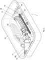
- the Figures 1 and 2 show a kit 10 according to the invention for producing and dispensing bone cement.
- the kit comprises a first container 12, a second container 70, a dispensing device 10, and a mixing device 74.
- the mixing device 74 is mechanically connected to the first container 12, so that after transferring the second component from the second container 70 into the first container 12, which contains the first component, the two components can be mixed with the mixing device 74 to obtain bone cement.
- the kit also contains a knee snorkel 54 and a flat snorkel 55, as well as a vacuum hose 50 for connecting the first container 12 to a vacuum source.
- the second component can advantageously be sucked into the first container 12 by means of a vacuum. However, operation without a vacuum is also possible with the embodiment shown here.
- a pumping device 11 is arranged, which can be used to pump the liquid into the first container.
- the pumping device can be designed as in DE 10 2015 106 899 B3 which is incorporated into this application by reference.
- the kit further comprises a packaging 77 in which the components are particularly packaged.
- the packaging 77 comprises a particularly deep-drawn tray 78 with a widened, circumferential edge and a lid 79 that is applied to the edge, for example, welded or glued.
- the packaging 77 has a substantially square basic shape.
- the mixing device 74 is partially arranged in the first container 12.
- A/B is between 1.0 and 1.2. In the case shown here, A/B is approximately 1.1.
- FIGS. 3 and 4 show other embodiments of a kit 1, in which the packaging 77 has an elongated basic shape.
- the kit 1 contains a device 85 for storing and opening the second container, which contains the second container 70.
- the device 85 is mechanically connected, in particular reversibly, to the first container 12. This facilitates use, since the connection does not have to be established first.
- Figure 3 A two-part squeezing device 10 is included.
- An adapter unit 26 of the squeezing device is mechanically connected to one end of the first container 12, specifically on the side opposite the device 85.
- a handle of the squeezing device 10 with threaded rod 20 and handle 24 is arranged separately therefrom and/or adjacent thereto.
- the adapter unit 26 can have, on the side facing away from the first container 12 with respect to the axial extent, a support surface for placing on a smooth surface and/or on a holder of the packaging (cf. Fig. 15A to 15C ). This facilitates the setting up of the first container 12 for mixing and/or after mixing.
- the squeezing device 10 is arranged completely separate from and/or next to the first container 12.
- the threaded rod 20 is screwed into the adapter unit 26.
- the kit 1 further comprises a vacuum hose 50, a knee pressurizer 52, a hip pressurizer 53, a knee snorkel 54, and a flat snorkel 55.
- Figure 5 shows an embodiment of the first container 12, a device 85 for storing and opening the second container 70 and a squeezing device 10, for example according to Figure 3 as described above.
- the device 85 contains the second container 70, which is designed as an ampoule 83 with a second component 82, namely a monomer liquid.
- the first component 81 is a bone cement powder located in the first container.
- the device 85 comprises a bending region 87, at which the device 85 can be bent to break off the head 84 of the ampoule 83.
- the head 84 and any glass splinters are then retained by a sieve, and the liquid can be discharged via the collection volume 86, optionally a filter element, the tubular element 57, and optionally another filter element into the second container.
- the first container 12 includes a nozzle (not shown here; see Fig. 15A ), which opens into a vacuum chamber 58. This is connected to the interior of the first container 12 by means of a grid or sieve. When a vacuum is applied, the liquid is sucked into the interior through the tubular element 57.
- the adapter unit 26 of the squeezing device comprises a support surface 60.
- the adapter unit can thus serve to hold the first container 12.
- the opening of the ampoule 83 and the transfer of the liquid into the first container 12, e.g. at least partially due to gravity, can take place when the first container 12 is in the upright position by means of the support surface 60.
- the adapter unit 26 comprises an internal thread 28 for screwing in the Figure 6 shown threaded rod 20 of the pressing device 10.
- An adapter unit 25 of the mixing device 74 is arranged on the opposite side of the first container 12.
- the mixing device 74 further comprises a rod 76 extending through the adapter unit 25, which connects a mixing element 75 to a handle 24.
- Figure 5 also shows a release mechanism of the mixing device 74. If an actuating element on the handle 24 is actuated in a suitable manner, in particular in the fully extended state, the handle 24 can be released from the rod 76.
- the rod 76 is designed as a hollow rod. After releasing the handle, the rod 76 can be used as a discharge tube for discharging the bone cement.
- the mixing element 75 remains inside the first container 12, for example in the area of the end face shown on the left, and in particular in a fixed state. This state is also shown in Figure 12 shown.
- the device 85 comprises an inner shell 90, in which the ampoule 83 is arranged, and an outer shell 89, which at least partially surrounds the inner shell 90.
- the inner shell 90 is axially displaceable with respect to the outer shell 89 at least in the direction of the first container, for example in the manner of a telescope, but can be held by a safety device 91, for example in the form of a removable safety clip.
- a safety device 91 for example in the form of a removable safety clip.
- the device 85 further includes a shearing element 88 for shearing off the head 84 of the ampoule 73.
- the shearing element typically includes a surface oriented obliquely to the longitudinal extent of the ampoule 83. If the inner sleeve 90 with the ampoule 83 is pushed toward the first container 12, the head 84 contacts the shearing element 88 and is thereby sheared off.
- Figure 8 is shown how it can be used in the above-described or a similar embodiment, in which the device 85 has an outer shell 89 and an inner shell 90 movable relative to the outer shell 89, for pumping the liquid into the first container 12.
- the volume in the device 85 is increased, and air flows into the device 85, for example, through a suitable valve in a lid of the device 85.
- the air displaces the liquid in the device 85, for example, in the collection volume 86, which previously flowed out of the ampoule 83, and presses it into the first container.
- a vacuum source can be dispensed with, and the kit can be used for cementing without any additional device.
- Figure 9 shows the separation of the device 85 from the first container 12. At least one retaining part 92, which previously established a connection, can be removed. Subsequently, easier mixing and/or pressing of the bone cement is possible. The separation can be irreversible.
- a closure element for example a slide, can close the opening in the first container 12 through which the tubular element 57 previously protruded.
- Figure 10 shows an embodiment in which the mixing device 74 is connected to the first container, and the squeezing device 10 and, in particular, a discharge pipe 51 are provided separately.
- the mixing device 74 comprises an adapter unit 25, and the squeezing device 10 comprises an adapter unit 26. Both adapter units can be attached to the same side of the first container 12.
- the discharge pipe 51 can be attached to the other side of the first container 12.
- Figure 11 shows another embodiment in which the adapter unit 25 for the mixing device 74 and the adapter unit 26 for the discharge device are arranged on opposite sides of the device.
- Figure 12 shows that Pressing out the bone cement 15 by means of the pressing device 10 through the discharge tube 51.
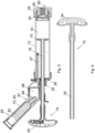
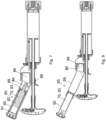
- the Figures 13 and 14 show a sectional view of a squeezing device 10 along the central longitudinal axis.
- the squeezing device 10 comprises an adapter unit 26 with a connecting area 37 for mechanically connecting to a first container.
- the connecting area 37 can be plugged or screwed onto a corresponding area of a first container.
- the adapter unit 26 has connecting elements 29 for establishing a bayonet connection. The direction of rotation for securing the bayonet connection corresponds to the direction of rotation for screwing in the threaded rod 20.
- the dispensing device 10 further comprises a threaded rod 20 with an external thread 22.
- the threaded rod 20 is guided through the through-opening 27, so that the external thread 22 engages the internal thread 28 located in the through-opening 27.
- the manually operable handle 24 for turning the threaded rod 20, shown on the right, is located.
- the adapter unit 26 causes the threaded rod to move axially, allowing the bone cement to be pressed out.
- the threaded rod 20 is configured to exert pressure or force on the bone cement.
- a pressure element 30 may be present for this purpose.
- the pressure element 30 serves to directly or indirectly exert pressure on bone cement in order to press it out of a first container.
- the pressure element 30 can move a piston of the first container, which in turn presses the bone cement out of the first container.
- the pressure element 30 will be discussed in more detail below.
- the threaded rod 20 can have an internal core, in the example shown here a metal rod 40, and/or a sheath, in the example shown here a plastic sheath 41.
- the metal rod 40 runs centrally inside the threaded rod 20 and contributes significantly to the mechanical stability of the threaded rod 20.
- the plastic sheath 41 forms the external thread 22 and protects the metal rod 40 from external influences.
- the metal rod 40 is preferably non-rotationally symmetrical in order to ensure a rotationally fixed connection to the handle 24 and/or the casing.
- the metal rod 40 can be hexagonal or square.
- a metal rod 40 with or made of stainless steel such as 316L is used.
- the metal rod 40 is completely encased in plastic.
- the thread is made of plastic. This provides a particularly smooth thread.
- the metal rod 40 is protected from external influences.
- the metal rod 40 has a diameter of at least 7 mm and/or at most 10 mm, preferably approximately or exactly 8 mm.
- the threaded rod 20 has a length L of at least 15 cm and/or at most 23 cm.
- the length of the threaded rod 20 is in particular at least 17 cm, preferably at least 19 cm and/or at most 23 cm, preferably at most 21 cm.
- the length L is measured between the outermost regions in which the external thread 22 is present.
- the adapter unit has a connecting region for attachment to the first container.
- the connecting region has an inner diameter D of at least 3.3 cm and/or at most 4.0 cm.
- the threaded rod contains no metal parts other than the metal rod.
- Figure 13 shows a completely unscrewed position of the threaded rod 20 from the adapter unit 26.
- Figure 14 a position is shown in which the threaded rod 20 has already been partially rotated through the adapter unit 26, as occurs when pressing out bone cement.
- the adapter unit 26 has a recess 35 into which the pressure element 30 can be completely received.
- the connecting area 37 of the adapter unit 26 shown on the left side remains free of the pressure element 30.
- the connecting area 37 be slipped over the corresponding end of the first container, or plugged or screwed onto it, without disturbing the pressure element 30.
- the pressure element 30 can - as in the Figures 13 and 14 shown - be constructed in two parts.
- a first part 31 can be fixedly connected to the threaded rod 20 so that it rotates together with the threaded rod 20 when it rotates.
- a second part 32 can be rotatably connected to the first part 31 so that the second part 32 does not rotate when the threaded rod 20 rotates. In this way, no rotational movement, but merely an axial compressive force is exerted on the bone cement 15 or the piston.
- the contacting surfaces of the first part 31 and the second part 32 are preferably flat and smooth in order to enable smooth rotation.
- the second part 32 of the pressure element 30 engages around the first part 31 of the pressure element 30 or forms an undercut 34 with it.
- the particularly circumferential outer rim of the second part 32 extends inward and engages behind the radially outer edge of the first part 31.
- the first part 31 and/or the second part 32 can be designed in the form of a plate.
- the second part 32 can have a diameter of at least 20 mm and/or at most 30 mm, for example approximately or exactly 25 mm.
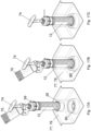
- FIGS 15A to 15C Different designs of the pressure element 30 are shown in the Figures 15A to 15C shown.
- the pressure element 30 presses on the bone cement to extrude it. In particular, this occurs indirectly, with the pressure element 30 pressing on a piston 13, which in turn is in contact with the bone cement.
- Figure 15A The pressure element 30 comprises only a first part 31, which is fixedly or rotatably connected to the threaded rod 20. The construction is particularly simple. However, the piston 13 may also rotate, which increases friction and thus the force required for pressing.
- Figure 15B A two-part construction of the pressure element 30 is shown. Between the first part 31 and the piston 13, there is a second part 32 of the pressure element 32, which is arranged rotatably with respect to the first part 31.
- the second part 32 extends over almost the entire inner diameter of the corresponding area of the piston, wherein advantageously at least a slight distance should remain between the inner circumferential surface of the piston 13 and the second part 32 so that no friction occurs.
- the second part 32 can be a flat disc.
- a lubricant such as silicone, is located between the two parts 31, 32 in order to to enable smooth rotation.
- the first part 31 can be connected to the threaded rod 20 in a rotationally fixed manner. There is rotation between the first part 31 and the second part 32, but no rotation between the second part 32 and the piston 13. This reduces friction and thus the required force.
- Figure 15C shows a further embodiment in which the first part 31 is designed as a flat disc located in a recess of the second part 32. The threaded rod only rotates the flat first part 31, and the second part 32 does not rotate with the piston 13.
- the parts 31, 32 transmit the force of the squeezing device evenly and prevent the piston 13 from tilting.
- Figure 16 shows an enlarged section through a threaded rod 20.
- This comprises an internal metal rod 40 and a plastic sheath 41 that completely encloses the metal rod 40.
- the outer diameter DA of the threaded rod 20 is shown, which corresponds to the maximum diameter between the elevations on both sides of the external thread 22.
- the inner diameter DI of the threaded rod 20 which corresponds to the minimum diameter between the depressions or valleys on both sides of the external thread 22.
- the thread has a thread depth of between 1 mm and 2 mm. The difference between the inner diameter DI and the outer diameter DA is therefore between 2 mm and 4 mm.
- a thread pitch 66 is delimited by dashed lines for illustrative purposes.
- the thread pitch corresponds to one complete rotation of the external thread 22 relative to the corresponding internal thread.
- the threaded rod 20 can be configured such that an outer surface of a thread pitch 66 of the external thread 22 is at most 370 mm2 .
- the outer surface of the thread is determined as the sum of the upper surface 61, which corresponds to the surface in the area of the thread elevation, the lower surface 62, which corresponds to the surface in the area of the thread depression, the first (ascending) flank surface 63, and the second (descending) flank surface 64.
- an outer surface of a thread turn of the external thread is at most 450 mm 2 , at most 430 mm 2 , at most 400 mm 2 , at most 370 mm 2 , at most 350 mm 2 , at most 330 mm 2 or at most 300 mm 2 .
- an outer surface of a thread turn of the external thread is at least 100 mm 2 , at least 130 mm 2 , at least 160 mm 2 , at least 180 mm 2 , at least 200 mm 2 , at least 215 mm 2 , at least 250 mm 2 , at least 280 mm 2 , at least 320 mm 2 or at least 350 mm 2 . These values may be particularly suitable depending on the design and materials.
- the threaded rod has an outer diameter DA of 14 mm, a thread depth (tooth height) of 1.5 mm, and a pitch of 4.5 mm. These values represent a good compromise between the advance per rotation and the force required to rotate it. Furthermore, this threaded rod 20 has a suitable self-locking feature, meaning it has no tendency to reverse itself when pressed out.
- FIGS 17A to 17B show the use of a holder 80 in the packaging 77.
- An adapter unit 26, in particular a squeezing device 10, is connected to the first container 12 on the side facing away from the device 85.
- the adapter unit 26 comprises a support surface 60.
- the support surface 60 corresponds to the holder 80, which is arranged or formed on the inside of the packaging 77, for example by deep drawing.
- Both the support surface 60 and the holder 80 are designed as three-dimensional structures that ensure good interlocking and thus a stable hold. If, on the other hand, the adapter unit 26 is designed as a hollow cylinder, it can be placed on a flat surface.
- Figure 17A shows the state shortly before the first container 12 is placed on the installation surface 80.
- Figure 17B shows the installed state.
- the device for storing and opening the second container with the second container 70 as well as the mixing device are connected to the first container.
- Figure 17C The aforementioned devices have been removed. Mixing can now begin. The firm and secure positioning of the first container 12 makes this particularly easy and safe.
Landscapes
- Health & Medical Sciences (AREA)
- Orthopedic Medicine & Surgery (AREA)
- Chemical & Material Sciences (AREA)
- Chemical Kinetics & Catalysis (AREA)
- Life Sciences & Earth Sciences (AREA)
- Transplantation (AREA)
- Heart & Thoracic Surgery (AREA)
- General Health & Medical Sciences (AREA)
- Engineering & Computer Science (AREA)
- Biomedical Technology (AREA)
- Veterinary Medicine (AREA)
- Public Health (AREA)
- Animal Behavior & Ethology (AREA)
- Surgery (AREA)
- Vascular Medicine (AREA)
- Physical Education & Sports Medicine (AREA)
- Oral & Maxillofacial Surgery (AREA)
- Cardiology (AREA)
- Nuclear Medicine, Radiotherapy & Molecular Imaging (AREA)
- Medical Informatics (AREA)
- Molecular Biology (AREA)
- Prostheses (AREA)
- Surgical Instruments (AREA)
Priority Applications (6)
| Application Number | Priority Date | Filing Date | Title |
|---|---|---|---|
| EP23214789.2A EP4566701A1 (fr) | 2023-12-07 | 2023-12-07 | Kit pour la préparation et l'extraction de ciment osseux et procédé |
| JP2024193343A JP2025092423A (ja) | 2023-12-07 | 2024-11-05 | 骨セメントを製造し、押し出すためのキット及び方法 |
| AU2024266888A AU2024266888B2 (en) | 2023-12-07 | 2024-11-26 | Kit for producing and extruding bone cement, and method |
| US18/965,528 US20250186095A1 (en) | 2023-12-07 | 2024-12-02 | Kit for producing and extruding bone cement, and method |
| CA3258122A CA3258122A1 (fr) | 2023-12-07 | 2024-12-02 | Trousse et méthode pour la production et l’extrusion de ciment acrylique |
| CN202411754125.3A CN120114234A (zh) | 2023-12-07 | 2024-12-02 | 用于生产和挤出骨水泥的套件以及方法 |
Applications Claiming Priority (1)
| Application Number | Priority Date | Filing Date | Title |
|---|---|---|---|
| EP23214789.2A EP4566701A1 (fr) | 2023-12-07 | 2023-12-07 | Kit pour la préparation et l'extraction de ciment osseux et procédé |
Publications (1)
| Publication Number | Publication Date |
|---|---|
| EP4566701A1 true EP4566701A1 (fr) | 2025-06-11 |
Family
ID=89121433
Family Applications (1)
| Application Number | Title | Priority Date | Filing Date |
|---|---|---|---|
| EP23214789.2A Pending EP4566701A1 (fr) | 2023-12-07 | 2023-12-07 | Kit pour la préparation et l'extraction de ciment osseux et procédé |
Country Status (6)
| Country | Link |
|---|---|
| US (1) | US20250186095A1 (fr) |
| EP (1) | EP4566701A1 (fr) |
| JP (1) | JP2025092423A (fr) |
| CN (1) | CN120114234A (fr) |
| AU (1) | AU2024266888B2 (fr) |
| CA (1) | CA3258122A1 (fr) |
Citations (35)
| Publication number | Priority date | Publication date | Assignee | Title |
|---|---|---|---|---|
| US589344A (en) | 1897-08-31 | S spencer eccleston | ||
| US4671263A (en) | 1984-07-11 | 1987-06-09 | Klaus Draenert | Device and process for mixing and applying bone cement |
| DE3640279A1 (de) | 1985-12-23 | 1987-06-25 | Mit Ab | Geraet zum mischen von knochenzement im vakuum |
| US4973168A (en) | 1989-01-13 | 1990-11-27 | Chan Kwan Ho | Vacuum mixing/bone cement cartridge and kit |
| WO1994016951A1 (fr) | 1993-01-29 | 1994-08-04 | Biomet, Inc. | Procede et appareil de conditionnement, de melange et d'apport de ciment osseux |
| US5344232A (en) | 1991-09-30 | 1994-09-06 | Stryker Corporation | Bone cement mixing and loading apparatus |
| WO1994026403A1 (fr) | 1993-05-10 | 1994-11-24 | Cemvac System Ab | Procede et dispositif permettant d'introduire des constituants d'un ciment pour les os dans un recipient ou ils doivent etre melanges |
| EP0692229A1 (fr) | 1994-07-16 | 1996-01-17 | MERCK PATENT GmbH | Dispositif pour mélanger et appliquer un ciment osseux |
| US5586821A (en) | 1995-10-10 | 1996-12-24 | Zimmer, Inc. | Bone cement preparation kit |
| US5638997A (en) | 1995-09-18 | 1997-06-17 | Zimmer, Inc. | Bone cement injector gun |
| EP0796653A2 (fr) | 1996-02-21 | 1997-09-24 | Kwan-Ho Chan | Dispositif et procédé pour le malaxage d'un ciment pour os |
| DE19718648A1 (de) | 1997-05-02 | 1998-11-05 | Merck Patent Gmbh | Verfahren und Vorrichtung zur Herstellung von steril verpacktem Knochenzement |
| WO1999067015A1 (fr) | 1997-05-21 | 1999-12-29 | Nikomed Aps | Appareil pour la preparation de ciment osseux |
| US6033105A (en) | 1996-11-15 | 2000-03-07 | Barker; Donald | Integrated bone cement mixing and dispensing system |
| EP1005901A2 (fr) | 1995-11-13 | 2000-06-07 | Cemvac System Aktiebolag | Procédé et dispositif pour mélanger des composants pour un ciment osseux dans un récipient de mélange |
| WO2000035506A1 (fr) | 1998-12-14 | 2000-06-22 | Ao Research Institute Davos | Procede de preparation de ciment osseux |
| EP1020167A2 (fr) | 1999-01-14 | 2000-07-19 | Bristol-Myers Squibb Company | Dispositif et procédé pour mélanger et appliquer du ciment osseux |
| US6676663B2 (en) | 2001-07-19 | 2004-01-13 | Higueras Antonio Perez | Applicator device for controllably injecting a surgical cement into bones |
| US20070211565A1 (en) * | 2006-03-10 | 2007-09-13 | Allegiance Corporation | Curable material mixing and delivery device |
| EP1886647A1 (fr) | 2006-08-11 | 2008-02-13 | Biomet Cementing Technologies AB | Dispositif de mélangeur de ciment osseux |
| EP1741413B1 (fr) | 2005-07-05 | 2009-09-02 | Biomet Cementing Technologies AB | Methode et dispositif pour mettre en contact et pour mélanger une composante poudreuse et une composante liquide, de préférence un polymère et un monomère, de préférence pour former du ciment osseux |
| DE102009031178B3 (de) | 2009-06-29 | 2010-09-16 | Heraeus Medical Gmbh | Vorrichtung zum Mischen und Austragen von Knochenzement |
| US20120224452A1 (en) | 2009-12-31 | 2012-09-06 | Melsheimer Jeffry S | Vertebroplasty cement mixer injector device |
| US8662736B2 (en) | 2010-07-29 | 2014-03-04 | Heraeus Medical Gmbh | Bone cement system |
| EP2393456B1 (fr) | 2009-02-06 | 2015-01-21 | Tecres S.P.A. | Mélangeur et procédé pour mélanger des composés diphasiques |
| EP2710972B1 (fr) | 2012-09-20 | 2016-04-13 | Heraeus Medical GmbH | Corps de vanne rotatif pour dispositif d'extraction pour ciments osseux |
| DE102015106899B3 (de) | 2015-05-04 | 2016-07-14 | Heraeus Medical Gmbh | Vorrichtung zum Mischen und Lagern von Polymethylmethacrylat-Knochenzement |
| EP2281532B1 (fr) | 2009-07-28 | 2016-09-07 | Heraeus Medical GmbH | Système de ciment osseux |
| EP2404864B1 (fr) | 2010-07-07 | 2017-04-12 | Heraeus Medical GmbH | Brise-ampoule |
| EP2711091B1 (fr) | 2012-09-20 | 2018-05-02 | Heraeus Medical GmbH | Dispositif d'extraction pour masses liquides |
| EP3584005A1 (fr) * | 2018-06-18 | 2019-12-25 | Heraeus Medical GmbH | Applicateur de ciment osseux pourvu de bâton mélangeur pouvant être abaissé et procédé de fabrication d'un ciment osseux |
| EP3054880B1 (fr) | 2013-10-10 | 2020-01-01 | Biomet SAS | Système indicateur de vide qui évite la libération en l'absence d'un niveau de vide approprié |
| CN213190021U (zh) | 2020-06-04 | 2021-05-14 | 百色市人民医院 | 一种用于椎体成型术的推注装置 |
| CN218220290U (zh) | 2022-06-22 | 2023-01-06 | 苏州名创医疗科技有限公司 | 一种经皮椎体成型术用辅助器械 |
| EP4282518A1 (fr) | 2022-05-23 | 2023-11-29 | Heraeus Medical GmbH | Dispositif et procédé de préparation de la pâte de ciment osseux |
Family Cites Families (4)
| Publication number | Priority date | Publication date | Assignee | Title |
|---|---|---|---|---|
| US9937057B2 (en) * | 2012-09-24 | 2018-04-10 | Isto Technologies, Inc. | Delivery device |
| DE102015116797B4 (de) * | 2015-10-02 | 2018-08-23 | Heraeus Medical Gmbh | Vorrichtung und Verfahren zum Lagern und Mischen eines Knochenzements |
| DE102018131266B4 (de) * | 2018-12-07 | 2021-12-23 | Heraeus Medical Gmbh | Vorrichtung zum Mischen eines Knochenzements mit Hohlraum zum Monomertransfer und Verfahren zur Herstellung eines Knochenzementteigs |
| US12533644B2 (en) * | 2019-06-14 | 2026-01-27 | Stryker Corporation | Mixing device and methods for making bone cement |
-
2023
- 2023-12-07 EP EP23214789.2A patent/EP4566701A1/fr active Pending
-
2024
- 2024-11-05 JP JP2024193343A patent/JP2025092423A/ja active Pending
- 2024-11-26 AU AU2024266888A patent/AU2024266888B2/en active Active
- 2024-12-02 CA CA3258122A patent/CA3258122A1/fr active Pending
- 2024-12-02 US US18/965,528 patent/US20250186095A1/en active Pending
- 2024-12-02 CN CN202411754125.3A patent/CN120114234A/zh active Pending
Patent Citations (44)
| Publication number | Priority date | Publication date | Assignee | Title |
|---|---|---|---|---|
| US589344A (en) | 1897-08-31 | S spencer eccleston | ||
| US4671263A (en) | 1984-07-11 | 1987-06-09 | Klaus Draenert | Device and process for mixing and applying bone cement |
| DE3640279A1 (de) | 1985-12-23 | 1987-06-25 | Mit Ab | Geraet zum mischen von knochenzement im vakuum |
| EP0380867B1 (fr) | 1989-01-13 | 1997-08-13 | Kwan-Ho Chan | Cartouche à vide pour mélanger du ciment chirurgical et nécessaire |
| US4973168A (en) | 1989-01-13 | 1990-11-27 | Chan Kwan Ho | Vacuum mixing/bone cement cartridge and kit |
| US5100241A (en) | 1989-01-13 | 1992-03-31 | Chan Kwan Ho | Vacuum mixing/bone cement cartridge and kit |
| US5344232A (en) | 1991-09-30 | 1994-09-06 | Stryker Corporation | Bone cement mixing and loading apparatus |
| WO1994016951A1 (fr) | 1993-01-29 | 1994-08-04 | Biomet, Inc. | Procede et appareil de conditionnement, de melange et d'apport de ciment osseux |
| WO1994026403A1 (fr) | 1993-05-10 | 1994-11-24 | Cemvac System Ab | Procede et dispositif permettant d'introduire des constituants d'un ciment pour les os dans un recipient ou ils doivent etre melanges |
| EP0692229A1 (fr) | 1994-07-16 | 1996-01-17 | MERCK PATENT GmbH | Dispositif pour mélanger et appliquer un ciment osseux |
| US5638997A (en) | 1995-09-18 | 1997-06-17 | Zimmer, Inc. | Bone cement injector gun |
| US5586821A (en) | 1995-10-10 | 1996-12-24 | Zimmer, Inc. | Bone cement preparation kit |
| US5624184A (en) | 1995-10-10 | 1997-04-29 | Chan; Kwan-Ho | Bone cement preparation kit having a breakable mixing shaft forming an output port |
| EP1005901A2 (fr) | 1995-11-13 | 2000-06-07 | Cemvac System Aktiebolag | Procédé et dispositif pour mélanger des composants pour un ciment osseux dans un récipient de mélange |
| EP1016452A2 (fr) | 1995-11-13 | 2000-07-05 | Cemvac System Aktiebolag | Procédé et dispositif pour mélanger des composants pour un ciment osseux dans un récipient de mélange |
| EP0796653B1 (fr) | 1996-02-21 | 2004-05-26 | Kwan-Ho Chan | Dispositif et procédé pour le malaxage d'un ciment pour os |
| EP0796653A2 (fr) | 1996-02-21 | 1997-09-24 | Kwan-Ho Chan | Dispositif et procédé pour le malaxage d'un ciment pour os |
| US6033105A (en) | 1996-11-15 | 2000-03-07 | Barker; Donald | Integrated bone cement mixing and dispensing system |
| US5997544A (en) | 1997-05-02 | 1999-12-07 | Merck Patent Gesellschaft Mit Beschrankter Haftung | Process and device for producing sterile-packed bone cement |
| DE19718648A1 (de) | 1997-05-02 | 1998-11-05 | Merck Patent Gmbh | Verfahren und Vorrichtung zur Herstellung von steril verpacktem Knochenzement |
| WO1999067015A1 (fr) | 1997-05-21 | 1999-12-29 | Nikomed Aps | Appareil pour la preparation de ciment osseux |
| WO2000035506A1 (fr) | 1998-12-14 | 2000-06-22 | Ao Research Institute Davos | Procede de preparation de ciment osseux |
| US6709149B1 (en) | 1998-12-14 | 2004-03-23 | Ao Research Institute Davos | Method of bone cement preparation |
| EP1020167A2 (fr) | 1999-01-14 | 2000-07-19 | Bristol-Myers Squibb Company | Dispositif et procédé pour mélanger et appliquer du ciment osseux |
| US6676663B2 (en) | 2001-07-19 | 2004-01-13 | Higueras Antonio Perez | Applicator device for controllably injecting a surgical cement into bones |
| EP1741413B1 (fr) | 2005-07-05 | 2009-09-02 | Biomet Cementing Technologies AB | Methode et dispositif pour mettre en contact et pour mélanger une composante poudreuse et une composante liquide, de préférence un polymère et un monomère, de préférence pour former du ciment osseux |
| US20070211565A1 (en) * | 2006-03-10 | 2007-09-13 | Allegiance Corporation | Curable material mixing and delivery device |
| EP1886647A1 (fr) | 2006-08-11 | 2008-02-13 | Biomet Cementing Technologies AB | Dispositif de mélangeur de ciment osseux |
| EP2393456B1 (fr) | 2009-02-06 | 2015-01-21 | Tecres S.P.A. | Mélangeur et procédé pour mélanger des composés diphasiques |
| DE102009031178B3 (de) | 2009-06-29 | 2010-09-16 | Heraeus Medical Gmbh | Vorrichtung zum Mischen und Austragen von Knochenzement |
| EP2269718B1 (fr) | 2009-06-29 | 2013-07-31 | Heraeus Medical GmbH | Dispositif de mélange et d'extraction de ciment osseux, et système de ciment osseux |
| EP2281532B1 (fr) | 2009-07-28 | 2016-09-07 | Heraeus Medical GmbH | Système de ciment osseux |
| US20120224452A1 (en) | 2009-12-31 | 2012-09-06 | Melsheimer Jeffry S | Vertebroplasty cement mixer injector device |
| EP2404864B1 (fr) | 2010-07-07 | 2017-04-12 | Heraeus Medical GmbH | Brise-ampoule |
| US8662736B2 (en) | 2010-07-29 | 2014-03-04 | Heraeus Medical Gmbh | Bone cement system |
| EP2710972B1 (fr) | 2012-09-20 | 2016-04-13 | Heraeus Medical GmbH | Corps de vanne rotatif pour dispositif d'extraction pour ciments osseux |
| EP2711091B1 (fr) | 2012-09-20 | 2018-05-02 | Heraeus Medical GmbH | Dispositif d'extraction pour masses liquides |
| EP3054880B1 (fr) | 2013-10-10 | 2020-01-01 | Biomet SAS | Système indicateur de vide qui évite la libération en l'absence d'un niveau de vide approprié |
| DE102015106899B3 (de) | 2015-05-04 | 2016-07-14 | Heraeus Medical Gmbh | Vorrichtung zum Mischen und Lagern von Polymethylmethacrylat-Knochenzement |
| EP3093067B1 (fr) | 2015-05-04 | 2020-01-22 | Heraeus Medical GmbH | Dispositif et procédé de melange et de stockage de ciment osseux en polymethacrylate de methyle |
| EP3584005A1 (fr) * | 2018-06-18 | 2019-12-25 | Heraeus Medical GmbH | Applicateur de ciment osseux pourvu de bâton mélangeur pouvant être abaissé et procédé de fabrication d'un ciment osseux |
| CN213190021U (zh) | 2020-06-04 | 2021-05-14 | 百色市人民医院 | 一种用于椎体成型术的推注装置 |
| EP4282518A1 (fr) | 2022-05-23 | 2023-11-29 | Heraeus Medical GmbH | Dispositif et procédé de préparation de la pâte de ciment osseux |
| CN218220290U (zh) | 2022-06-22 | 2023-01-06 | 苏州名创医疗科技有限公司 | 一种经皮椎体成型术用辅助器械 |
Also Published As
| Publication number | Publication date |
|---|---|
| AU2024266888A1 (en) | 2025-06-26 |
| CN120114234A (zh) | 2025-06-10 |
| JP2025092423A (ja) | 2025-06-19 |
| US20250186095A1 (en) | 2025-06-12 |
| AU2024266888B2 (en) | 2025-10-09 |
| CA3258122A1 (fr) | 2025-10-31 |
Similar Documents
| Publication | Publication Date | Title |
|---|---|---|
| DE102010019217B4 (de) | Kartuschensystem | |
| DE60021633T2 (de) | Hilfswerkzeug zum Auspressen eines chemischen Wirkstoffes, Kneter zum Vorbereiten und Auspressen eines chemischen Wirkstoffes, und Verfahren zur Verwendung derselben | |
| EP3643398B1 (fr) | Dispositif et procédé de fourniture de ciment osseux | |
| EP3584005B1 (fr) | Applicateur de ciment osseux pourvu de bâton mélangeur pouvant être abaissé et procédé de fabrication d'un ciment osseux | |
| EP2730332B1 (fr) | Dispositif de mélange et d'extraction d'une masse pâteuse | |
| DE102017104854B4 (de) | Zweiteilige Lager- und Mischvorrichtung zur Herstellung eines Knochenzements und Verfahren hierzu | |
| DE102010026497B4 (de) | Vakuumzementiersystem | |
| EP2987551B1 (fr) | Dispositif de sortie dote d'un melangeur entraine elastiquement et procédé | |
| DE102010019220B4 (de) | Kartuschensystem mit verbundenen Förderkolben | |
| DE102014113816B3 (de) | Pasten-Applikationssystem zum Lagern zweier Ausgangskomponenten, zum Mischen der Ausgangskomponenten zu einer Paste und zum Applizieren der Paste sowie Verfahren zum Mischen und Austreiben einer Paste | |
| EP1520562B1 (fr) | Dispositif pour mélanger et distribuer des substances liquides et pulvérulentes pour l'utilisation médicale. | |
| EP0261182A1 (fr) | Dispositif et procede pour le transvasement d'un melange visqueux de substances, en particulier du ciment d'os. | |
| EP3505237B1 (fr) | Dispositif et procede de mélange de ciment osseux pourvu d'écarteur dans un logement à ampoule | |
| EP3662991B1 (fr) | Dispositif et procédé de mélange d'un ciment osseux pourvu de cavité pour un transfert au monomère | |
| EP3479895B1 (fr) | Mélangeur de ciment osseux, de liquide et de poudre pourvu de raccordement de gaz de pression et procédé | |
| EP3213707A1 (fr) | Système mélangeur et de stockage de composants de ciment sous forme de pâte et procédé associé | |
| EP3584004A1 (fr) | Applicateur de ciment osseux pourvu de bâton mélangeur pouvant être abaissé et procédé de fabrication d'un ciment osseux | |
| DE102016113467A1 (de) | Knochenzement-Applikator mit Dreiwege-Ventil zur Druckentlastung | |
| EP4257232B1 (fr) | Dispositif et procédé de préparation de la pâte de ciment osseux | |
| EP3415226B1 (fr) | Applicateur de ciment osseux pourvu d'élément conducteur et logement de fermeture | |
| EP4282518A1 (fr) | Dispositif et procédé de préparation de la pâte de ciment osseux | |
| EP4309774A1 (fr) | Dispositif et procédé de fourniture d'une pâte de ciment osseux | |
| EP4545027B1 (fr) | Dispositif pour exprimer du ciment osseux, utilisation et système | |
| EP3811881A1 (fr) | Dispositif de distribution du ciment osseux |
Legal Events
| Date | Code | Title | Description |
|---|---|---|---|
| PUAI | Public reference made under article 153(3) epc to a published international application that has entered the european phase |
Free format text: ORIGINAL CODE: 0009012 |
|
| STAA | Information on the status of an ep patent application or granted ep patent |
Free format text: STATUS: REQUEST FOR EXAMINATION WAS MADE |
|
| 17P | Request for examination filed |
Effective date: 20231207 |
|
| AK | Designated contracting states |
Kind code of ref document: A1 Designated state(s): AL AT BE BG CH CY CZ DE DK EE ES FI FR GB GR HR HU IE IS IT LI LT LU LV MC ME MK MT NL NO PL PT RO RS SE SI SK SM TR |