EP3055143B1 - Pneumatique pour vehicule - Google Patents
Pneumatique pour vehicule Download PDFInfo
- Publication number
- EP3055143B1 EP3055143B1 EP14749751.5A EP14749751A EP3055143B1 EP 3055143 B1 EP3055143 B1 EP 3055143B1 EP 14749751 A EP14749751 A EP 14749751A EP 3055143 B1 EP3055143 B1 EP 3055143B1
- Authority
- EP
- European Patent Office
- Prior art keywords
- portions
- circle
- sipes
- features
- profile
- Prior art date
- Legal status (The legal status is an assumption and is not a legal conclusion. Google has not performed a legal analysis and makes no representation as to the accuracy of the status listed.)
- Active
Links
Images

Classifications
-
- B—PERFORMING OPERATIONS; TRANSPORTING
- B60—VEHICLES IN GENERAL
- B60C—VEHICLE TYRES; TYRE INFLATION; TYRE CHANGING; CONNECTING VALVES TO INFLATABLE ELASTIC BODIES IN GENERAL; DEVICES OR ARRANGEMENTS RELATED TO TYRES
- B60C11/00—Tyre tread bands; Tread patterns; Anti-skid inserts
- B60C11/03—Tread patterns
- B60C11/13—Tread patterns characterised by the groove cross-section, e.g. for buttressing or preventing stone-trapping
- B60C11/1376—Three dimensional block surfaces departing from the enveloping tread contour
-
- B—PERFORMING OPERATIONS; TRANSPORTING
- B60—VEHICLES IN GENERAL
- B60C—VEHICLE TYRES; TYRE INFLATION; TYRE CHANGING; CONNECTING VALVES TO INFLATABLE ELASTIC BODIES IN GENERAL; DEVICES OR ARRANGEMENTS RELATED TO TYRES
- B60C11/00—Tyre tread bands; Tread patterns; Anti-skid inserts
- B60C11/03—Tread patterns
- B60C11/12—Tread patterns characterised by the use of narrow slits or incisions, e.g. sipes
- B60C11/1204—Tread patterns characterised by the use of narrow slits or incisions, e.g. sipes with special shape of the sipe
-
- B—PERFORMING OPERATIONS; TRANSPORTING
- B60—VEHICLES IN GENERAL
- B60C—VEHICLE TYRES; TYRE INFLATION; TYRE CHANGING; CONNECTING VALVES TO INFLATABLE ELASTIC BODIES IN GENERAL; DEVICES OR ARRANGEMENTS RELATED TO TYRES
- B60C11/00—Tyre tread bands; Tread patterns; Anti-skid inserts
- B60C11/03—Tread patterns
- B60C11/12—Tread patterns characterised by the use of narrow slits or incisions, e.g. sipes
- B60C11/1236—Tread patterns characterised by the use of narrow slits or incisions, e.g. sipes with special arrangements in the tread pattern
-
- B—PERFORMING OPERATIONS; TRANSPORTING
- B60—VEHICLES IN GENERAL
- B60C—VEHICLE TYRES; TYRE INFLATION; TYRE CHANGING; CONNECTING VALVES TO INFLATABLE ELASTIC BODIES IN GENERAL; DEVICES OR ARRANGEMENTS RELATED TO TYRES
- B60C11/00—Tyre tread bands; Tread patterns; Anti-skid inserts
- B60C11/03—Tread patterns
- B60C11/12—Tread patterns characterised by the use of narrow slits or incisions, e.g. sipes
- B60C11/1204—Tread patterns characterised by the use of narrow slits or incisions, e.g. sipes with special shape of the sipe
- B60C2011/1209—Tread patterns characterised by the use of narrow slits or incisions, e.g. sipes with special shape of the sipe straight at the tread surface
-
- B—PERFORMING OPERATIONS; TRANSPORTING
- B60—VEHICLES IN GENERAL
- B60C—VEHICLE TYRES; TYRE INFLATION; TYRE CHANGING; CONNECTING VALVES TO INFLATABLE ELASTIC BODIES IN GENERAL; DEVICES OR ARRANGEMENTS RELATED TO TYRES
- B60C11/00—Tyre tread bands; Tread patterns; Anti-skid inserts
- B60C11/03—Tread patterns
- B60C11/12—Tread patterns characterised by the use of narrow slits or incisions, e.g. sipes
- B60C11/1204—Tread patterns characterised by the use of narrow slits or incisions, e.g. sipes with special shape of the sipe
- B60C2011/1213—Tread patterns characterised by the use of narrow slits or incisions, e.g. sipes with special shape of the sipe sinusoidal or zigzag at the tread surface
-
- B—PERFORMING OPERATIONS; TRANSPORTING
- B60—VEHICLES IN GENERAL
- B60C—VEHICLE TYRES; TYRE INFLATION; TYRE CHANGING; CONNECTING VALVES TO INFLATABLE ELASTIC BODIES IN GENERAL; DEVICES OR ARRANGEMENTS RELATED TO TYRES
- B60C11/00—Tyre tread bands; Tread patterns; Anti-skid inserts
- B60C11/03—Tread patterns
- B60C11/12—Tread patterns characterised by the use of narrow slits or incisions, e.g. sipes
- B60C2011/129—Sipe density, i.e. the distance between the sipes within the pattern
Definitions
- the invention relates to a tread pattern of a vehicle tire with radially raised and limited by grooves profile positive - such as tread elements or tread ribs - which are bounded in the radial direction R of the tire by a radially outer surface, and spaced apart in profile positive sipes formed.
- Such pneumatic vehicle tires are known. It is known to form substantially parallel extending fine incisions to achieve a better grip on snow in the tread blocks of profile block rows or in profile ribs. When unrolling the sipes form additional grip edges. In addition, snow can press into the opening sipes and thereby further improve the snow grip. It is known to form the sipes rectilinear or wavy.
- the sipes in the profile element In such a way that the highest possible density of sipes is achieved.
- the distances of the sipes must be positioned far enough apart that, depending on the requirement, sufficiently high rigidity (bending stiffness) of the profile positive formed with the sipes can be ensured in order to be able to ensure the respectively desired required power transmission for dry braking and traction properties.
- the distances between the juxtaposed sipes in each case so large that the vent valves between the sipes can be positioned with sufficient distance from the sipes.
- the distances of the sipes to each other and the position of the sipes in the profile element and the density of the arrangement of sipes of a profile element by the requirements of the vent are additionally limited.
- vent valves only outside the extension range of the sipes.
- the sipes In order to ensure adequate ventilation in such training, the sipes must be spaced far enough apart be positioned so that a safe discharge of the air between the sipes during the molding can be ensured. This means that even with this training large distances between the sipes are given due to the required ventilation. For longer sipes with greater extension of the incision length there is still the danger that adequate ventilation is not given.
- vent valves with smaller valve plates could allow the formation of a higher density of fine cuts in the profile element to a limited extent.
- valves with smaller valve disk diameter tend to increasingly higher susceptibility to clogging, so that the use is very complicated to handle with a high cost of cleaning and maintenance and with increasing hindrance of automated production.
- the invention has for its object to provide such treads with sipes in which optimum venting possible in the molding using advanced design options for optimum snow grip.
- the object is achieved by the formation of a tread pattern of a vehicle tire with radially raised and limited by grooves profile positive - such as tread elements or tread ribs - which are bounded in the radial direction R of the tire by a radially outer surface, and formed in profile positive spaced-apart sipes, solved according to the features of claim 1, in which are formed in the profile positive fine incisions, which along their main extension direction in the radially outer surface of successively arranged - in particular aligned in the main direction - aligned first rectilinear and second circular segment-line sections, and at least those first rectilinear sections of a sipe, which two second connect circular segment-shaped sections with each other, are formed parallel to each other, wherein the second, niksegmentlinienförmige section is formed at least each with a circular radius R K , wherein within the circle at least some niksegmentlinienförmiger sections each a survey of the rubber material is formed and wherein this survey
- vent valves can thus be positioned in the position of the circle of semicircular sections and thus also be used in the extension of the individual sipe itself for venting.
- adjacent sipes can be positioned with a closer distance to each other while still ensuring adequate ventilation within the network of sipes.
- a further optimization of the snow grip properties can be optimally implemented according to the respective requirements of the tire and its intended use, without additional impairments by defaults.
- the freedom of design for the design of vehicle tires with good snow grip properties can thus be significantly expanded.
- a tread pattern according to the features of claim 2 wherein the formed in the profile positive sipes are aligned with their main extension direction in the radially outer surface substantially parallel to each other.
- a tread pattern according to the features of claim 6, wherein at least those first rectilinear portions of a sipe, which each connect two second circular segment-line-shaped sections, formed parallel to each other - and in particular on a common line g - are formed.
- first rectilinear portions of a sipe which each connect two second circular segment-line-shaped sections, formed parallel to each other - and in particular on a common line g - are formed.
- a tread strip according to the features of claim 7, wherein between two along the main extension direction of a sipe in the radially outer surface adjacent, consecutively formed second, circular segment-shaped sections each having a rectilinear Section of the extension length a with 5mm ⁇ a ⁇ 15mm is formed.
- tread pattern according to the features of claim 8, wherein the semicircles of the two interconnected by a first portion second portions are each aligned to the same side of the straight line of the straight section.
- tread pattern according to the features of claim 9, wherein the semicircles of two in the main extension direction of a sipe - in particular directly formed into one another - successively arranged second sections are formed aligned on opposite side of the adjacent first rectilinear portions.
- FIGS. 1 to 4 show a section of a tread pattern of a pneumatic vehicle tire for passenger cars (PKW) with - in Fig.1 shown - radially raised Profile block elements 1, 2, 3 and 4, which are each spaced apart in a known manner by grooves 5, 6 and 9 from each other.
- the tread block elements 1, 3 and 4 are in the circumferential direction U of the pneumatic vehicle tire in the in FIG. 1 limited upward direction by a transverse groove 7.
- the profile block elements 1, 2 and 3 are in the circumferential direction U in the in FIG. 1 limited direction of rotation in each case by a transverse groove 8.
- the profile block elements 2 and 4 are arranged one behind the other in the circumferential direction and spaced from each other by a transverse groove 9.
- the tread block element 1 is spaced in the axial direction A of the pneumatic vehicle tire by the tread block elements 2 and 4 by a groove 5 which is aligned with its main extension direction in the circumferential direction U.
- the tread block element 1 and the tread block element 3 are spaced apart in the axial direction A of the pneumatic vehicle tire by a groove 6 which is aligned with its main direction of extent in the circumferential direction U of the vehicle pneumatic tire.
- the tread block elements 1, 2, 3 and 4 are limited in the radial direction R of the pneumatic vehicle tire to the outside by a radially outer surface 13.
- the tread block element 1 - as in the FIGS. 1 to 4 is shown - formed by a plurality of parallel to each other, each at a distance b from each other successively arranged sipes 10.
- the sipes 10 each extend through the entire profile block element 1 and open at both extension ends into different grooves bounding the profile block element 1.
- open in the middle extension portion of the tread block element sipe 10 open into the profile block element to different sides limiting transverse grooves 7 and 8.
- the formed in the groove 5 and the transverse groove 7 included extension portion of the tread block element 1 sipes 10 open into the transverse groove 7 and into the groove 5.
- the sipes 10 formed in the extension section of the tread block element 1 enclosed by the transverse groove 8 and the groove 6 open into the transverse groove 8 and into the groove 6.
- the sipe 10 is formed respectively along its extension direction in the radially outer surface of rectilinear extension portions 14 and semicircular extension portions 15.
- the rectilinear extension sections 14 and the semicircular extension sections 15 are arranged in succession along the extension direction of the sipe 10 in alternating sequence.
- the rectilinear extension sections 14 of a sipe 10 lie in each case on a common straight line g.
- the semicircular extension sections 15 in this case form a semicircle with the radius R K around a midpoint M. arranged on the straight outer surface 13 on the straight line g.
- a 8mm is selected.
- t is formed with t ⁇ 25mm.
- the sipes 10 of the tread block element 1 are each arranged one behind the other, that the centers M are arranged in each of the circumferential groove 8 out next semi-circular extension portions 15 of the sipes 10 on a common straight line and that the midpoints M of the semi-circular sections 15th the sipes 10, which are respectively arranged closest to the circumferential groove 7, are likewise arranged on a common straight line.
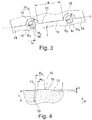
- the vent valves in the tire vulcanization mold are respectively positioned to be in contact with the tire surface with its circular valve disk concentric with the circle of the semicircular extension portions 15 of the sipes 10 with the tire vulcanization mold closed. They then form in the vulcanization valve discprints 16 on the tire surface, which, for example - as in the FIGS. 3 and 4 shown formed concentric with the circle of semicircular elevations 15, circular or circular segment-shaped elevations with a radius R Z to the center M of the semicircular line-shaped extension portions 15 and with a maximum measured in the radial direction R of the tire extension height h.
- the radius R K of the semicircular extension portions 15 is dimensioned such that R K ⁇ (R Z +0.5 mm).
- the height h of such valve disk impressions can typically be up to 2 mm in size.
- valve head impression 16 is shown as a circular elevation.
- the valve disk impressions 16 are in other - not shown - execution partly only part-circular elevations or annular or part-annular elevations with the outer diameter R Z to the center point M.
- Fig.1 can be clearly seen in the profile block element 1, are formed in this way between two perpendicular to the main extension direction of the sipes 10 of the profile block element 1 successively arranged sipes 10 within the profile block element 1 in high density valve plate impressions 16 of vent valves and indeed within the main extension of the respective sipe 10th
- louver sheets vent valves are arranged.
- the distances b between the successively arranged sipes are formed with b ⁇ (2 R K ).
- FIGS. 1 and 3 is the example of the profile block element 1, an embodiment shown in which the semicircular extension portions 15 of a sipe 10 are each formed on the same side of the line g of the sipe 10 out.
- an exemplary embodiment is illustrated with reference to the sipes 12, in which the semicircular extension sections 15 interconnected by the rectilinear extension section 14 are each aligned with respect to their straight line g to a different side.
- a semicircular extension section with the reference numeral 15 and the semi-circular extension section oriented in the opposite direction are shown with the reference numeral 15 '.
- a further embodiment is shown with reference to the profile block element 2, in which in each case a semicircular extension portion 15 and a corresponding to the opposite side aligned semi-circular extension portion 15 'of a sipe 11 immediately adjacent tangentially merge into one another.
- This pair of semicircular extension sections 15 and 15 'arranged one behind the other in the extension direction of the fine incision 11 is connected to the adjacent adjacent pair of semicircular extension sections 15 and 15' along the extension of the fine section 11, again by a rectilinear extension section 14 of the extension length a - such as the profile block element 1 described - connected.
- Fig.1 can be seen on the example of the profile block element 1, that the profile block element 1 is formed with a plurality of successively arranged sipes 10 of the type according to the invention.
- the profile block element 2 shows an embodiment of a profile block element with only two circumferentially successively arranged fine sipes 11 according to the invention.
- the profile block element 4 shows a further embodiment of a profile block element formed in the circumferential direction U with a short extension, in which only a single sipe 11 with an alternating sequence of rectilinear extension sections 14 and circular extension sections 15 or 15 'is formed.
- the sipes 10 and 11 are along their extent in the radial direction R of the tire, starting from the radially outer surface 13 inwardly in one embodiment - such as in Fig.2 and Figure 4 is shown - extends rectilinearly formed.
- the sipes 10 and 11, respectively are formed to extend rectilinearly along their radial extent from the radially outer surface toward the inside, including an inclination angle to the radial direction R.
Landscapes
- Engineering & Computer Science (AREA)
- Mechanical Engineering (AREA)
- Tires In General (AREA)
Claims (9)
- Profil de bande de roulement d'un pneu de véhicule doté d'éléments positifs de sculpture (1), radialement convexes et délimités par des sillons (5, 6, 7, 8) - tels que des éléments de bloc de sculpture ou des nervures, lesquels sont délimités dans la direction radiale R du pneu par une surface extérieure radiale (13), et doté d'incisions fines (10) réalisées dans les éléments positifs de sculpture (1) et écartées l'une de l'autre, dans lequel des incisions fines (10) sont réalisées dans l'élément positif de sculpture (1), lesquelles sont réalisées à partir de premières sections rectilignes (14) et de deuxièmes sections en forme d'arc de cercle (15) agencées l'une derrière l'autre le long de leur direction d'étendue principale dans la surface extérieure radiale (13) - en particulier orientées dans la direction d'étendue principale - et dans lequel au moins chacune des premières sections rectilignes (14) d'une incision fine (10), lesquelles relient respectivement l'une à l'autre deux deuxièmes sections en forme d'arc de cercle (15), sont réalisées parallèlement l'une à l'autre, caractérisé en ce que la deuxième section en forme d'arc de cercle (15) est réalisée respectivement avec au moins un rayon RK, dans lequel une élévation (16) du matériau de caoutchouc est respectivement réalisée à l'intérieur du cercle d'au moins plusieurs sections en forme d'arc de cercle (15) et dans lequel cette élévation (16) est réalisée de forme circulaire, annulaire, en forme d'arc de cercle ou de segment d'anneau, avec un rayon externe de la forme circulaire ou annulaire Rz tel que RK ≥ (RZ + 0,5 mm).
- Profil de bande de roulement selon les caractéristiques de la revendication 1, dans lequel les incisions fines (10) réalisées dans l'élément positif de sculpture (1) sont orientées, avec leur direction d'étendue principale, de manière essentiellement parallèle l'une à l'autre dans la surface extérieure radiale (13).
- Profil de bande de roulement selon les caractéristiques de la revendication 1 ou 2, dans lequel l'arc de cercle des deuxièmes sections en forme d'arc de cercle (15) est réalisé respectivement avec un rayon RK tel que RK ≥ 2 mm.
- Profil de bande de roulement selon les caractéristiques de la revendication 3, dans lequel le rayon RK est réalisé tel que RK ≤ 3 mm.
- Profil de bande de roulement selon les caractéristiques d'une ou plusieurs des revendications précédentes, dans lequel l'arc de cercle des deuxièmes sections en forme d'arc de cercle (15) est un demi-cercle.
- Profil de bande de roulement selon les caractéristiques d'une ou plusieurs des revendications précédentes, dans lequel au moins chacune des premières sections rectilignes (14) d'une incision fine (10), lesquelles relient respectivement l'une à l'autre deux deuxièmes sections en forme d'arc de cercle (15), sont réalisées parallèlement l'une à l'autre et sur une droite g commune.
- Profil de bande de roulement selon les caractéristiques d'une ou plusieurs des revendications précédentes, dans lequel une section rectiligne (14) de longueur d'étendue a telle que 5 mm ≤ a ≤ 15 mm est respectivement réalisée entre deux deuxièmes sections en forme d'arc de cercle (15) réalisées l'une derrière l'autre et adjacentes dans la surface extérieure radiale (13) le long de la direction d'étendue principale d'une incision fine (10).
- Profil de bande de roulement selon les caractéristiques des revendications 7 et 5, dans lequel les demi-cercles des deux deuxièmes sections (15) reliées l'une à l'autre par une première section (14) sont réalisés respectivement comme orientés vers le même côté de la droite g de la section rectiligne (14).
- Profil de bande de roulement selon les caractéristiques de la revendication 5, dans lequel les demi-cercles de deux deuxièmes sections (15, 15') agencées l'une derrière l'autre dans la direction d'étendue principale d'une incision fine (11, 12) - en particulier réalisées comme passant directement de l'une à l'autre - sont réalisés comme orientés vers des côtés opposés des premières sections rectilignes (14) qui les jouxtent.
Applications Claiming Priority (2)
| Application Number | Priority Date | Filing Date | Title |
|---|---|---|---|
| DE201310111196 DE102013111196A1 (de) | 2013-10-10 | 2013-10-10 | Fahrzeugluftreifen |
| PCT/EP2014/066447 WO2015051933A1 (fr) | 2013-10-10 | 2014-07-31 | Pneumatique de véhicule |
Publications (2)
| Publication Number | Publication Date |
|---|---|
| EP3055143A1 EP3055143A1 (fr) | 2016-08-17 |
| EP3055143B1 true EP3055143B1 (fr) | 2019-10-09 |
Family
ID=51300714
Family Applications (1)
| Application Number | Title | Priority Date | Filing Date |
|---|---|---|---|
| EP14749751.5A Active EP3055143B1 (fr) | 2013-10-10 | 2014-07-31 | Pneumatique pour vehicule |
Country Status (4)
| Country | Link |
|---|---|
| EP (1) | EP3055143B1 (fr) |
| CN (1) | CN105636800B (fr) |
| DE (1) | DE102013111196A1 (fr) |
| WO (1) | WO2015051933A1 (fr) |
Families Citing this family (1)
| Publication number | Priority date | Publication date | Assignee | Title |
|---|---|---|---|---|
| CN108859613B (zh) * | 2017-05-16 | 2021-09-24 | 住友橡胶工业株式会社 | 轮胎 |
Citations (1)
| Publication number | Priority date | Publication date | Assignee | Title |
|---|---|---|---|---|
| DE102007060559A1 (de) * | 2007-12-15 | 2009-06-18 | Continental Aktiengesellschaft | Fahrzeugluftreifen |
Family Cites Families (5)
| Publication number | Priority date | Publication date | Assignee | Title |
|---|---|---|---|---|
| JPH062442B2 (ja) * | 1987-05-28 | 1994-01-12 | 東洋ゴム工業株式会社 | 湿潤路及び氷雪路のトラクシヨン性能を改良した空気入りタイヤ |
| AT404244B (de) * | 1994-01-20 | 1998-09-25 | Semperit Ag | Fahrzeugreifen mit einem laufstreifen |
| FR2921586B1 (fr) * | 2007-09-27 | 2011-05-06 | Soc Tech Michelin | Bande de roulement de pneu comprenant des plots de gomme |
| JP4605297B1 (ja) * | 2009-07-01 | 2011-01-05 | 横浜ゴム株式会社 | 空気入りタイヤ |
| FR2971732B1 (fr) * | 2011-02-17 | 2013-02-01 | Michelin Soc Tech | Bande de roulement pour pneumatique poids lourd de type remorque et element moulant |
-
2013
- 2013-10-10 DE DE201310111196 patent/DE102013111196A1/de not_active Withdrawn
-
2014
- 2014-07-31 EP EP14749751.5A patent/EP3055143B1/fr active Active
- 2014-07-31 WO PCT/EP2014/066447 patent/WO2015051933A1/fr not_active Ceased
- 2014-07-31 CN CN201480055585.5A patent/CN105636800B/zh active Active
Patent Citations (1)
| Publication number | Priority date | Publication date | Assignee | Title |
|---|---|---|---|---|
| DE102007060559A1 (de) * | 2007-12-15 | 2009-06-18 | Continental Aktiengesellschaft | Fahrzeugluftreifen |
Also Published As
| Publication number | Publication date |
|---|---|
| DE102013111196A1 (de) | 2015-04-16 |
| WO2015051933A1 (fr) | 2015-04-16 |
| CN105636800B (zh) | 2018-08-21 |
| CN105636800A (zh) | 2016-06-01 |
| EP3055143A1 (fr) | 2016-08-17 |
Similar Documents
| Publication | Publication Date | Title |
|---|---|---|
| EP2867037B1 (fr) | Pneu de vehicule | |
| EP3079875B1 (fr) | Moule de vulcanisation | |
| EP2790930B1 (fr) | Pneu de véhicules utilitaires | |
| EP3208113B1 (fr) | Pneumatiques de véhicule | |
| EP2773519B1 (fr) | Pneu pour véhicule | |
| DE102010000272A1 (de) | Fahrzeugluftreifen | |
| EP3019346B1 (fr) | Profil de bande de roulement d'un pneu de véhicule | |
| DE102012105120A1 (de) | Fahrzeugluftreifen | |
| EP2803501A1 (fr) | Pneu de véhicule | |
| EP3122574B1 (fr) | Pneu de vehicule | |
| EP2644408B1 (fr) | Profil de bande de roulement d'un bandage pneumatique de véhicule | |
| EP3055143B1 (fr) | Pneumatique pour vehicule | |
| EP3321078A1 (fr) | Moule de vulcanisation et pneu de véhicule | |
| DE19612829C2 (de) | Vulkanisationsform mit Segmenten für die Herstellung von Fahrzeugluftreifen und Verfahren zur Herstellung der Segmente | |
| EP2388154B1 (fr) | Profil de bande de roulement d'un bandage pneumatique de véhicule | |
| EP2634015B1 (fr) | Profil de bande de roulement d'un pneu de véhicule | |
| EP3272509B1 (fr) | Moule de vulcanisation et pneu de véhicule | |
| EP2860049B1 (fr) | Pneus de véhicule | |
| DE102013108384A1 (de) | Vulkanisierform für Fahrzeugreifen und Fahrzeugreifen, welcher mit einer vorgenannten Vulkanisierform heizgepresst ist | |
| EP2412548B1 (fr) | Pneu de véhicule | |
| EP3825151B1 (fr) | Pneu avec bande de roulement | |
| EP3366494A1 (fr) | Pneu | |
| EP2353886A1 (fr) | Profil de bande de roulement d'un pneu de véhicule | |
| EP2554404B1 (fr) | Profil de bande de roulement d´un pneu de véhicule | |
| EP2554405A1 (fr) | Profil de bande de roulement d´un pneu de véhicule |
Legal Events
| Date | Code | Title | Description |
|---|---|---|---|
| PUAI | Public reference made under article 153(3) epc to a published international application that has entered the european phase |
Free format text: ORIGINAL CODE: 0009012 |
|
| 17P | Request for examination filed |
Effective date: 20160510 |
|
| AK | Designated contracting states |
Kind code of ref document: A1 Designated state(s): AL AT BE BG CH CY CZ DE DK EE ES FI FR GB GR HR HU IE IS IT LI LT LU LV MC MK MT NL NO PL PT RO RS SE SI SK SM TR |
|
| AX | Request for extension of the european patent |
Extension state: BA ME |
|
| DAX | Request for extension of the european patent (deleted) | ||
| STAA | Information on the status of an ep patent application or granted ep patent |
Free format text: STATUS: EXAMINATION IS IN PROGRESS |
|
| 17Q | First examination report despatched |
Effective date: 20171113 |
|
| RIC1 | Information provided on ipc code assigned before grant |
Ipc: B60C 11/13 20060101ALI20190503BHEP Ipc: B60C 11/12 20060101AFI20190503BHEP |
|
| GRAP | Despatch of communication of intention to grant a patent |
Free format text: ORIGINAL CODE: EPIDOSNIGR1 |
|
| STAA | Information on the status of an ep patent application or granted ep patent |
Free format text: STATUS: GRANT OF PATENT IS INTENDED |
|
| INTG | Intention to grant announced |
Effective date: 20190617 |
|
| GRAS | Grant fee paid |
Free format text: ORIGINAL CODE: EPIDOSNIGR3 |
|
| GRAA | (expected) grant |
Free format text: ORIGINAL CODE: 0009210 |
|
| STAA | Information on the status of an ep patent application or granted ep patent |
Free format text: STATUS: THE PATENT HAS BEEN GRANTED |
|
| AK | Designated contracting states |
Kind code of ref document: B1 Designated state(s): AL AT BE BG CH CY CZ DE DK EE ES FI FR GB GR HR HU IE IS IT LI LT LU LV MC MK MT NL NO PL PT RO RS SE SI SK SM TR |
|
| REG | Reference to a national code |
Ref country code: GB Ref legal event code: FG4D Free format text: NOT ENGLISH |
|
| REG | Reference to a national code |
Ref country code: CH Ref legal event code: EP |
|
| REG | Reference to a national code |
Ref country code: IE Ref legal event code: FG4D Free format text: LANGUAGE OF EP DOCUMENT: GERMAN |
|
| REG | Reference to a national code |
Ref country code: DE Ref legal event code: R096 Ref document number: 502014012824 Country of ref document: DE |
|
| REG | Reference to a national code |
Ref country code: AT Ref legal event code: REF Ref document number: 1188360 Country of ref document: AT Kind code of ref document: T Effective date: 20191115 |
|
| REG | Reference to a national code |
Ref country code: SE Ref legal event code: TRGR |
|
| REG | Reference to a national code |
Ref country code: NL Ref legal event code: MP Effective date: 20191009 |
|
| REG | Reference to a national code |
Ref country code: LT Ref legal event code: MG4D |
|
| PG25 | Lapsed in a contracting state [announced via postgrant information from national office to epo] |
Ref country code: LT Free format text: LAPSE BECAUSE OF FAILURE TO SUBMIT A TRANSLATION OF THE DESCRIPTION OR TO PAY THE FEE WITHIN THE PRESCRIBED TIME-LIMIT Effective date: 20191009 Ref country code: FI Free format text: LAPSE BECAUSE OF FAILURE TO SUBMIT A TRANSLATION OF THE DESCRIPTION OR TO PAY THE FEE WITHIN THE PRESCRIBED TIME-LIMIT Effective date: 20191009 Ref country code: BG Free format text: LAPSE BECAUSE OF FAILURE TO SUBMIT A TRANSLATION OF THE DESCRIPTION OR TO PAY THE FEE WITHIN THE PRESCRIBED TIME-LIMIT Effective date: 20200109 Ref country code: LV Free format text: LAPSE BECAUSE OF FAILURE TO SUBMIT A TRANSLATION OF THE DESCRIPTION OR TO PAY THE FEE WITHIN THE PRESCRIBED TIME-LIMIT Effective date: 20191009 Ref country code: PL Free format text: LAPSE BECAUSE OF FAILURE TO SUBMIT A TRANSLATION OF THE DESCRIPTION OR TO PAY THE FEE WITHIN THE PRESCRIBED TIME-LIMIT Effective date: 20191009 Ref country code: NO Free format text: LAPSE BECAUSE OF FAILURE TO SUBMIT A TRANSLATION OF THE DESCRIPTION OR TO PAY THE FEE WITHIN THE PRESCRIBED TIME-LIMIT Effective date: 20200109 Ref country code: ES Free format text: LAPSE BECAUSE OF FAILURE TO SUBMIT A TRANSLATION OF THE DESCRIPTION OR TO PAY THE FEE WITHIN THE PRESCRIBED TIME-LIMIT Effective date: 20191009 Ref country code: PT Free format text: LAPSE BECAUSE OF FAILURE TO SUBMIT A TRANSLATION OF THE DESCRIPTION OR TO PAY THE FEE WITHIN THE PRESCRIBED TIME-LIMIT Effective date: 20200210 Ref country code: NL Free format text: LAPSE BECAUSE OF FAILURE TO SUBMIT A TRANSLATION OF THE DESCRIPTION OR TO PAY THE FEE WITHIN THE PRESCRIBED TIME-LIMIT Effective date: 20191009 Ref country code: GR Free format text: LAPSE BECAUSE OF FAILURE TO SUBMIT A TRANSLATION OF THE DESCRIPTION OR TO PAY THE FEE WITHIN THE PRESCRIBED TIME-LIMIT Effective date: 20200110 |
|
| PG25 | Lapsed in a contracting state [announced via postgrant information from national office to epo] |
Ref country code: IS Free format text: LAPSE BECAUSE OF FAILURE TO SUBMIT A TRANSLATION OF THE DESCRIPTION OR TO PAY THE FEE WITHIN THE PRESCRIBED TIME-LIMIT Effective date: 20200224 Ref country code: RS Free format text: LAPSE BECAUSE OF FAILURE TO SUBMIT A TRANSLATION OF THE DESCRIPTION OR TO PAY THE FEE WITHIN THE PRESCRIBED TIME-LIMIT Effective date: 20191009 Ref country code: HR Free format text: LAPSE BECAUSE OF FAILURE TO SUBMIT A TRANSLATION OF THE DESCRIPTION OR TO PAY THE FEE WITHIN THE PRESCRIBED TIME-LIMIT Effective date: 20191009 |
|
| PG25 | Lapsed in a contracting state [announced via postgrant information from national office to epo] |
Ref country code: AL Free format text: LAPSE BECAUSE OF FAILURE TO SUBMIT A TRANSLATION OF THE DESCRIPTION OR TO PAY THE FEE WITHIN THE PRESCRIBED TIME-LIMIT Effective date: 20191009 |
|
| REG | Reference to a national code |
Ref country code: DE Ref legal event code: R097 Ref document number: 502014012824 Country of ref document: DE |
|
| PG2D | Information on lapse in contracting state deleted |
Ref country code: IS |
|
| PG25 | Lapsed in a contracting state [announced via postgrant information from national office to epo] |
Ref country code: EE Free format text: LAPSE BECAUSE OF FAILURE TO SUBMIT A TRANSLATION OF THE DESCRIPTION OR TO PAY THE FEE WITHIN THE PRESCRIBED TIME-LIMIT Effective date: 20191009 Ref country code: DK Free format text: LAPSE BECAUSE OF FAILURE TO SUBMIT A TRANSLATION OF THE DESCRIPTION OR TO PAY THE FEE WITHIN THE PRESCRIBED TIME-LIMIT Effective date: 20191009 Ref country code: RO Free format text: LAPSE BECAUSE OF FAILURE TO SUBMIT A TRANSLATION OF THE DESCRIPTION OR TO PAY THE FEE WITHIN THE PRESCRIBED TIME-LIMIT Effective date: 20191009 Ref country code: CZ Free format text: LAPSE BECAUSE OF FAILURE TO SUBMIT A TRANSLATION OF THE DESCRIPTION OR TO PAY THE FEE WITHIN THE PRESCRIBED TIME-LIMIT Effective date: 20191009 Ref country code: IS Free format text: LAPSE BECAUSE OF FAILURE TO SUBMIT A TRANSLATION OF THE DESCRIPTION OR TO PAY THE FEE WITHIN THE PRESCRIBED TIME-LIMIT Effective date: 20200209 |
|
| PLBE | No opposition filed within time limit |
Free format text: ORIGINAL CODE: 0009261 |
|
| STAA | Information on the status of an ep patent application or granted ep patent |
Free format text: STATUS: NO OPPOSITION FILED WITHIN TIME LIMIT |
|
| PG25 | Lapsed in a contracting state [announced via postgrant information from national office to epo] |
Ref country code: IT Free format text: LAPSE BECAUSE OF FAILURE TO SUBMIT A TRANSLATION OF THE DESCRIPTION OR TO PAY THE FEE WITHIN THE PRESCRIBED TIME-LIMIT Effective date: 20191009 Ref country code: SM Free format text: LAPSE BECAUSE OF FAILURE TO SUBMIT A TRANSLATION OF THE DESCRIPTION OR TO PAY THE FEE WITHIN THE PRESCRIBED TIME-LIMIT Effective date: 20191009 Ref country code: SK Free format text: LAPSE BECAUSE OF FAILURE TO SUBMIT A TRANSLATION OF THE DESCRIPTION OR TO PAY THE FEE WITHIN THE PRESCRIBED TIME-LIMIT Effective date: 20191009 |
|
| 26N | No opposition filed |
Effective date: 20200710 |
|
| PG25 | Lapsed in a contracting state [announced via postgrant information from national office to epo] |
Ref country code: SI Free format text: LAPSE BECAUSE OF FAILURE TO SUBMIT A TRANSLATION OF THE DESCRIPTION OR TO PAY THE FEE WITHIN THE PRESCRIBED TIME-LIMIT Effective date: 20191009 |
|
| PG25 | Lapsed in a contracting state [announced via postgrant information from national office to epo] |
Ref country code: MC Free format text: LAPSE BECAUSE OF FAILURE TO SUBMIT A TRANSLATION OF THE DESCRIPTION OR TO PAY THE FEE WITHIN THE PRESCRIBED TIME-LIMIT Effective date: 20191009 |
|
| REG | Reference to a national code |
Ref country code: CH Ref legal event code: PL |
|
| GBPC | Gb: european patent ceased through non-payment of renewal fee |
Effective date: 20200731 |
|
| REG | Reference to a national code |
Ref country code: BE Ref legal event code: MM Effective date: 20200731 |
|
| PG25 | Lapsed in a contracting state [announced via postgrant information from national office to epo] |
Ref country code: LU Free format text: LAPSE BECAUSE OF NON-PAYMENT OF DUE FEES Effective date: 20200731 Ref country code: FR Free format text: LAPSE BECAUSE OF NON-PAYMENT OF DUE FEES Effective date: 20200731 Ref country code: LI Free format text: LAPSE BECAUSE OF NON-PAYMENT OF DUE FEES Effective date: 20200731 Ref country code: GB Free format text: LAPSE BECAUSE OF NON-PAYMENT OF DUE FEES Effective date: 20200731 Ref country code: CH Free format text: LAPSE BECAUSE OF NON-PAYMENT OF DUE FEES Effective date: 20200731 |
|
| PG25 | Lapsed in a contracting state [announced via postgrant information from national office to epo] |
Ref country code: BE Free format text: LAPSE BECAUSE OF NON-PAYMENT OF DUE FEES Effective date: 20200731 |
|
| PG25 | Lapsed in a contracting state [announced via postgrant information from national office to epo] |
Ref country code: IE Free format text: LAPSE BECAUSE OF NON-PAYMENT OF DUE FEES Effective date: 20200731 |
|
| REG | Reference to a national code |
Ref country code: AT Ref legal event code: MM01 Ref document number: 1188360 Country of ref document: AT Kind code of ref document: T Effective date: 20200731 |
|
| PG25 | Lapsed in a contracting state [announced via postgrant information from national office to epo] |
Ref country code: AT Free format text: LAPSE BECAUSE OF NON-PAYMENT OF DUE FEES Effective date: 20200731 |
|
| PG25 | Lapsed in a contracting state [announced via postgrant information from national office to epo] |
Ref country code: TR Free format text: LAPSE BECAUSE OF FAILURE TO SUBMIT A TRANSLATION OF THE DESCRIPTION OR TO PAY THE FEE WITHIN THE PRESCRIBED TIME-LIMIT Effective date: 20191009 Ref country code: MT Free format text: LAPSE BECAUSE OF FAILURE TO SUBMIT A TRANSLATION OF THE DESCRIPTION OR TO PAY THE FEE WITHIN THE PRESCRIBED TIME-LIMIT Effective date: 20191009 Ref country code: CY Free format text: LAPSE BECAUSE OF FAILURE TO SUBMIT A TRANSLATION OF THE DESCRIPTION OR TO PAY THE FEE WITHIN THE PRESCRIBED TIME-LIMIT Effective date: 20191009 |
|
| PG25 | Lapsed in a contracting state [announced via postgrant information from national office to epo] |
Ref country code: MK Free format text: LAPSE BECAUSE OF FAILURE TO SUBMIT A TRANSLATION OF THE DESCRIPTION OR TO PAY THE FEE WITHIN THE PRESCRIBED TIME-LIMIT Effective date: 20191009 |
|
| PGFP | Annual fee paid to national office [announced via postgrant information from national office to epo] |
Ref country code: SE Payment date: 20220720 Year of fee payment: 9 |
|
| REG | Reference to a national code |
Ref country code: DE Ref legal event code: R081 Ref document number: 502014012824 Country of ref document: DE Owner name: CONTINENTAL REIFEN DEUTSCHLAND GMBH, DE Free format text: FORMER OWNER: CONTINENTAL REIFEN DEUTSCHLAND GMBH, 30165 HANNOVER, DE |
|
| PG25 | Lapsed in a contracting state [announced via postgrant information from national office to epo] |
Ref country code: SE Free format text: LAPSE BECAUSE OF NON-PAYMENT OF DUE FEES Effective date: 20230801 |
|
| PGFP | Annual fee paid to national office [announced via postgrant information from national office to epo] |
Ref country code: DE Payment date: 20250731 Year of fee payment: 12 |