EP3366494A1 - Pneu - Google Patents
Pneu Download PDFInfo
- Publication number
- EP3366494A1 EP3366494A1 EP18151544.6A EP18151544A EP3366494A1 EP 3366494 A1 EP3366494 A1 EP 3366494A1 EP 18151544 A EP18151544 A EP 18151544A EP 3366494 A1 EP3366494 A1 EP 3366494A1
- Authority
- EP
- European Patent Office
- Prior art keywords
- groove
- depth
- extension
- tread pattern
- features
- Prior art date
- Legal status (The legal status is an assumption and is not a legal conclusion. Google has not performed a legal analysis and makes no representation as to the accuracy of the status listed.)
- Withdrawn
Links
Images


Classifications
-
- B—PERFORMING OPERATIONS; TRANSPORTING
- B60—VEHICLES IN GENERAL
- B60C—VEHICLE TYRES; TYRE INFLATION; TYRE CHANGING; CONNECTING VALVES TO INFLATABLE ELASTIC BODIES IN GENERAL; DEVICES OR ARRANGEMENTS RELATED TO TYRES
- B60C11/00—Tyre tread bands; Tread patterns; Anti-skid inserts
- B60C11/03—Tread patterns
- B60C11/12—Tread patterns characterised by the use of narrow slits or incisions, e.g. sipes
- B60C11/1272—Width of the sipe
- B60C11/1281—Width of the sipe different within the same sipe, i.e. enlarged width portion at sipe bottom or along its length
-
- B—PERFORMING OPERATIONS; TRANSPORTING
- B60—VEHICLES IN GENERAL
- B60C—VEHICLE TYRES; TYRE INFLATION; TYRE CHANGING; CONNECTING VALVES TO INFLATABLE ELASTIC BODIES IN GENERAL; DEVICES OR ARRANGEMENTS RELATED TO TYRES
- B60C11/00—Tyre tread bands; Tread patterns; Anti-skid inserts
- B60C11/03—Tread patterns
- B60C11/12—Tread patterns characterised by the use of narrow slits or incisions, e.g. sipes
- B60C11/1204—Tread patterns characterised by the use of narrow slits or incisions, e.g. sipes with special shape of the sipe
- B60C11/1218—Three-dimensional shape with regard to depth and extending direction
-
- B—PERFORMING OPERATIONS; TRANSPORTING
- B60—VEHICLES IN GENERAL
- B60C—VEHICLE TYRES; TYRE INFLATION; TYRE CHANGING; CONNECTING VALVES TO INFLATABLE ELASTIC BODIES IN GENERAL; DEVICES OR ARRANGEMENTS RELATED TO TYRES
- B60C11/00—Tyre tread bands; Tread patterns; Anti-skid inserts
- B60C11/03—Tread patterns
- B60C11/12—Tread patterns characterised by the use of narrow slits or incisions, e.g. sipes
- B60C11/1204—Tread patterns characterised by the use of narrow slits or incisions, e.g. sipes with special shape of the sipe
- B60C2011/1209—Tread patterns characterised by the use of narrow slits or incisions, e.g. sipes with special shape of the sipe straight at the tread surface
Definitions
- the invention relates to a tread pattern of a vehicle tire - in particular a car vehicle tire - with limited by grooves profile elements and formed in profile elements sipes, wherein the profile elements in the radial direction R outwardly from a radially outer surface and the sipes radially inward from a Incision base and be bounded on either side of the incision reason each of a cutting wall, wherein the sipe is formed in each case with a thickness D, with sipes, which are spaced from each other, from the incision bottom and spaced from the radially outer surface, limited extension portions are formed, in which the sipe is formed with an increased thickness D ', wherein the limited extension portion in each case by a groove in one of the two cutting walls in the radial direction R extending groove in the radial direction R in the cutting wall measured extension length H 2 is formed, which extends in the radial direction R outward in the cut wall to a position at a distance H 1 > 0 from the radially outer surface and ends there
- tread patterns of passenger car pneumatic tires for achieving good grip properties on snow and ice, and thus for achieving good winter grip characteristics with fine cuts in the groove block limited profile block elements.
- the fine cuts showed additional grip edges for better grip on snow and ice.
- snow or mud included which also the snow snow grip is improved.
- the usual sipes are formed with correspondingly formed incision walls with substantially the same sipe thickness, which are optimized for use in wintry operation.
- tread block elements of winter tires form the sipes of the tread block elements with a three-dimensional structure, wherein the two sipe walls bounding the sipe incision are formed with a substantially corresponding extent course.
- the known three-dimensional sipes are essentially designed for winter operation.
- the thin sipes with their three-dimensional structure are not suitable for additional cooling.
- these sipes would have to be formed with great thickness, whereby however their stiffening effect and thus the winter suitability would be reduced again.
- the negative portion of the profile achieved by the sip would thus be significantly increased, whereby the Abriebeigenticianen could also be adversely affected.
- sipes at their radially inner extension end with channel-shaped through holes.
- these lamellar plates are reinforced by additional ribs, said ribs is continuously wider radially inward to the molding for forming the tubular thickening out and strikes with the widest cross-section of the molding for forming the tubular thickening ,
- the sipe produced by this training then has in the incision wall in the radial direction extending wells, which are getting larger in the radial direction and their greatest width at the confluence with the sipe radially inwardly delimiting channel-shaped passage opening has.
- the cross-section is at the radially inner extension end of the sipe and the grooves produced by the ribs at the transition to the channel.
- This sipe design may improve drainage of the tread pattern over its lifetime.
- the generated material overhang above the channel leads to an increase in the block compression of the profile block, whereby the rolling resistance is adversely affected.
- the invention is therefore an object of the invention to allow such treads with sipes in which, despite low Void, good Abriebeigenschaften and cooling effects of the tread pattern with good releasability and rolling resistance is possible.
- the object is achieved according to the invention by the formation of a tread pattern of a vehicle tire - in particular a car vehicle tire - with profile elements formed by grooves and with sipes formed in profile elements, wherein the profile elements in the radial direction R outwardly from a radially outer surface and the sipes radially are bounded on the inside by an incision base and on either side of the incision base by an incision wall, wherein the fine incision is formed in each case with a thickness D, with fine incisions which are formed with limited, extended extension sections spaced from each other by the incision base and from the radially outer surfaces, in which the sipe is formed with an increased thickness D ', wherein the limited extension portion in each case by a groove extending in one of the two cutting walls in the radial direction R with a radial Direction R in the incision wall measured extension length H 2 is formed, which extends in the radial direction R outwardly in the cut wall to a position at a distance H 1 > 0 from the
- the shape of the sipe and the groove formed in the sipe wall is optimized by these flowing transitions without undercuts without risk of tearing.
- the fine incision thickness which is optimal for the grip effect on snow and ice, can be implemented in the sipe over a large extension section of the sipe.
- the formation of the sipe with the thickenings in the form of these grooves in a side wall allows targeted provision additional surface and space within the sipe for optimized heat dissipation.
- the heat dissipation through air or water in the sipe is favored by the radially inward and outward flowing transitions of the grooves and thus favored trouble-free flows.
- additional cooling properties can be achieved be made in the field of sipes, without affecting abrasion or rolling resistance.
- the vehicle pneumatic tire can be optimized for winter use and yet be improved in its use at higher temperatures.
- a vehicle tire according to the features of claim 8 wherein distributed along the extension of the sipe in the radially outer surface in a sipe wall a plurality of such grooves are arranged one behind the other, wherein adjacent successively arranged grooves of a sipe wall with measured in the incision wall distance d are positioned with 3mm ⁇ d ⁇ 20mm to each other.
- H 1 is formed with 0.5mm ⁇ H 1 ⁇ 1mm.
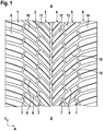
- FIGS. 1 to 6 show a tread pattern of a pneumatic vehicle tire of a passenger car (car), which is formed in a known manner from in the axial direction A of the vehicle pneumatic tire adjacent profile block rows 1, 2, 3, 4, 5 and 6.
- the profile block rows 1, 2, 3, 4, 5 and 6 each extend in Circumferential direction U of the pneumatic vehicle tire over its entire circumference.
- the equatorial plane ⁇ - ⁇ of the pneumatic vehicle tire is drawn.
- the profile block rows 1 and 6 are each formed in a tire shoulder and form the shoulder profile block rows.
- the profile block row 1 is formed in a known manner from over the circumference of the vehicle pneumatic tire, arranged in the circumferential direction U behind the other and each spaced by transverse grooves 8 spaced apart profile block elements 9.
- the profile block row 2 is distributed in a known manner from over the entire circumference of the vehicle pneumatic tire, arranged in the circumferential direction U behind the other and each separated by transverse grooves 8 profile block elements 10.
- the profile block row 3 is in a known manner from over the entire circumference of the vehicle pneumatic tire distributed in the circumferential direction U arranged one behind the other and each separated by transverse grooves 8 profile block elements 11.
- the profile block row 4 is distributed in a known manner from over the entire circumference of the vehicle pneumatic tire, arranged in the circumferential direction U behind the other and each separated by transverse grooves 8 profile block elements 12.
- the profile block row 5 is formed in a known manner from over the entire circumference of the vehicle pneumatic tire, arranged in the circumferential direction U behind the other and each separated by transverse grooves 8 profile block elements 13 of known type.
- the profile block row 14 is formed in a known manner from over the entire circumference of the vehicle pneumatic tire, arranged in the circumferential direction U behind the other and each separated by transverse grooves 8 profile block elements 14.
- the profile block row 1 and the profile block row 2 are arranged side by side in the axial direction A of the pneumatic vehicle tire, wherein the profile block elements 9 of the profile block row 1 and the profile block elements 10 of the profile block row 2 in the axial direction A by circumferentially oriented grooves 7 are separated.
- the profile block row 2 and the profile block row 3 are arranged side by side in the axial direction A of the pneumatic vehicle tire, the profile block elements 10 of the profile block row 2 and the profile block elements 11 of the profile block row 3 circumferentially oriented grooves 7 are separated from each other.
- the profile block row 3 and the profile block row 4 are arranged side by side in the axial direction A of the pneumatic vehicle tire, the profile block elements 11 of the profile block row 3 and the profile block elements 12 of the profile block row 4 are separated from each other by circumferentially oriented grooves 7.
- the profile block row 4 and the profile block row 5 are arranged side by side in the axial direction A of the pneumatic vehicle tire, the profile block elements 12 of the profile block row 4 and the profile block row 13 of the profile block row 5 in the axial direction A by circumferentially oriented grooves 7 are separated from each other.
- the profile block row 5 and the profile block row 6 are arranged side by side in the axial direction A, the profile block elements 13 of the profile block row 5 and the profile block row 14 of the profile block row 6 are separated by circumferentially oriented grooves 7 in the axial direction A of the pneumatic vehicle tire.
- the circumferential grooves 7 which separate the tread block elements 11 and the tread block elements 12 form a circumferential groove aligned in the circumferential direction U of the pneumatic vehicle tire and extending over the entire circumference of the pneumatic vehicle tire.
- tread block element 13 As in the FIGS. 3 to 6 is shown as an example of a tread block element 13, the tread block elements 9, 10, 11, 12, 13 and 14 are limited in the radial direction R of the pneumatic vehicle tire to the outside each by a radially outer surface 17, which within the ground contact width of the pneumatic vehicle tire, the road contact surface of the tire forms.
- the profile block elements 9, 10, 11, 12, 13 and 14 are each formed with fine incisions 15 in their radially outer surface 17. These extend parallel to the respective profile block element 9, 10, 11, 12, 13 and 14 delimiting transverse grooves 8 through the profile block element 9, 10, 11, 12, 13 and 14 and open into the respective profile block element 9, 10, 11, 12, 13 and 14 delimiting circumferential grooves 7.
- the circumferential grooves 7 and the transverse grooves 8 are bounded inwards in the radial direction R in each case by a groove bottom 16.
- the circumferential grooves 7 and the transverse grooves 8 are formed with a starting from the radially outer surface 17 of each adjacent profile block elements 9, 10, 11, 12, 13 and 14 in the radial direction R to the groove bottom 16 Rillenentiefe T R , wherein the groove depth is formed with 6mm ⁇ T R ⁇ 10mm.
- a fine incision 15 of a tread block element 13 the sipes 15 in the radial direction R inwardly each bounded by a recess base 20 and formed with an incision depth H F , which in the radial direction R, starting from the radially outer surface 17 to the incision 20 is measured.
- the sipe 15 is bounded on both sides of the recess base 20 each by a sipe wall 18 , .19.
- the sipe wall 18 delimits the sipe 15 on one side of the sipe base 20.
- the sipe wall 19 bounds the sipe 15 on the other side of the sipe base 20.
- the sipe walls 18 and 19 extend along the entire extent of the sipe 15 in the radially outer surface 17 and in the radial direction R, starting from the fine incision base 20 to the radially outer surface 17.
- the incision wall 18 along the extension of the fine incision 15 in the radially outer surface 17, starting from the radially outer surface 17 in a radially outer extension portion 25 of the measured in the radial direction R extension height H 1 along its entire extent substantially flat , Similarly, the incision wall 18 in a radially inner extension portion 23 of measured in the radial direction R extension height H 3 , which is measured by the recess base 20 radially outward, with a along its extension in the extension direction of the sipe 15 in the radially outer surface 17 substantially Plan surface 17 is formed.
- the incision wall 13 with its central extension portion 24 which is the radial Main extension portion of the trench wall 18 forms and extends over an extension height H 2 in the radial direction formed.
- the incision wall 18 along the extension of the fine incision 15 in the radially outer surface 17 in the central extension portion 24 is formed with a plurality of in the extension direction of the sipe 15 in the radially outer surface 17 successively arranged and spaced grooves 21, which with extend their main extension direction in the radial direction R of the pneumatic vehicle tire over the entire extension height H 2 of the central extension portion 24.
- the grooves 21 are formed in the cut-in wall 18 each along its main extension direction with a width B. Adjacent grooves 21 are arranged in the incision wall 18 at a distance d from each other.
- the grooves 21 are formed with a perpendicular to the incision wall 18 measured depth T and bounded by a groove bottom 22.
- the groove bottom 22 is formed in the cutting plane perpendicular to the cutting wall 18 along the main extension direction of the groove 21 in this case with a curved, for example circular arc-shaped sectional contour line.
- the point P is formed in the middle extension third of the central extension portion 24 of the extension height H 2 .
- the height H 1 is designed for new tires with 0.5mm ⁇ H 1 ⁇ 1mm.
- the height H 2 is formed with 4mm ⁇ H 2 ⁇ 9mm.
- the depth Tmax is chosen to be 0.3mm ⁇ T max ⁇ 1mm.
- Tmax 0.5 mm is formed.
- the grooves 7 and 8 are formed with groove widths 2mm to 8mm.
- the grooves 21 are aligned in their main extension direction in the incision wall 18 along its extension from radially inward to radially outward, including an inclination angle ⁇ with 0 ° ⁇ ⁇ ⁇ 20 ° to the radial direction R.
- ⁇ 0 ° is selected.
- the Einschittswand 19 is formed in an analogous manner along its radial extent with a radially inner extension portion 23 of the extension height H 3 , with a central extension portion 24 of the heightening height H 2 and with a radially outer extension portion 25 of the height H 1 .
- the incision wall 19 is within the extension section 25 and within the extension section 23 each substantially flat and within the extension section 24 with analogous to those in the FIGS. 3 and 4 formed and described above grooves 21.
- the grooves 21 of the cut-in wall 18 are each positioned longitudinally of the main extension of the sipe 15 in the radially outer surface 17 offset from the grooves 21 of the cut-in wall 19.
- an incision 21 of the incision wall 18 is formed between the position of two adjacent grooves 21 of the incision wall 19 and an incision 21 of the incision wall 19 between the position of two adjacent grooves 21 of the incision wall 18.
- an incision 21 of the incision wall 19 is positioned in the same position of the sipe 15 as an incision 21 of the incision wall 19 respectively along the main extension of the sipe 15 in the radially outer surface 17.
- only the sipes 15 of the profile block row 5 are formed with such grooves 21 and the sipes 15 of the profile block rows 1,2,3,4 and 6 not.
Landscapes
- Engineering & Computer Science (AREA)
- Mechanical Engineering (AREA)
- Tires In General (AREA)
Applications Claiming Priority (1)
| Application Number | Priority Date | Filing Date | Title |
|---|---|---|---|
| DE102017203166.2A DE102017203166A1 (de) | 2017-02-27 | 2017-02-27 | Fahrzeugreifen |
Publications (1)
| Publication Number | Publication Date |
|---|---|
| EP3366494A1 true EP3366494A1 (fr) | 2018-08-29 |
Family
ID=60972102
Family Applications (1)
| Application Number | Title | Priority Date | Filing Date |
|---|---|---|---|
| EP18151544.6A Withdrawn EP3366494A1 (fr) | 2017-02-27 | 2018-01-15 | Pneu |
Country Status (2)
| Country | Link |
|---|---|
| EP (1) | EP3366494A1 (fr) |
| DE (1) | DE102017203166A1 (fr) |
Cited By (1)
| Publication number | Priority date | Publication date | Assignee | Title |
|---|---|---|---|---|
| EP3401124B1 (fr) * | 2017-05-12 | 2020-02-19 | Continental Reifen Deutschland GmbH | Profilé de bande roulement d'un pneu de véhicule |
Citations (10)
| Publication number | Priority date | Publication date | Assignee | Title |
|---|---|---|---|---|
| JPH01101205A (ja) * | 1987-10-12 | 1989-04-19 | Bridgestone Corp | 空気入りタイヤ |
| JPH01285409A (ja) * | 1988-05-13 | 1989-11-16 | Yokohama Rubber Co Ltd:The | 氷雪路用重荷重空気入りタイヤ |
| JP2005329793A (ja) * | 2004-05-19 | 2005-12-02 | Toyo Tire & Rubber Co Ltd | 空気入りタイヤ |
| JP2006298057A (ja) * | 2005-04-18 | 2006-11-02 | Sumitomo Rubber Ind Ltd | 空気入りタイヤ |
| JP2008290573A (ja) * | 2007-05-24 | 2008-12-04 | Bridgestone Corp | 空気入りタイヤ |
| JP2010208428A (ja) * | 2009-03-09 | 2010-09-24 | Toyo Tire & Rubber Co Ltd | 空気入りタイヤ |
| DE102010012595A1 (de) | 2009-03-26 | 2010-09-30 | Toyo Tire & Rubber Co., Ltd. | Luftreifen |
| US20120006458A1 (en) * | 2008-12-05 | 2012-01-12 | Michelin Recherche Et Technique S.A. | Tire Tread Comprising Incisions and Recesses |
| WO2016053307A1 (fr) | 2014-09-30 | 2016-04-07 | Compagnie Generale Des Etablissements Michelin | Raidisseurs pour éléments de moulage de lamelles |
| WO2017112504A1 (fr) * | 2015-12-22 | 2017-06-29 | Bridgestone Americas Tire Operations, Llc | Pneumatique ayant des motifs de lamelles tridimensionnels apparents |
-
2017
- 2017-02-27 DE DE102017203166.2A patent/DE102017203166A1/de not_active Withdrawn
-
2018
- 2018-01-15 EP EP18151544.6A patent/EP3366494A1/fr not_active Withdrawn
Patent Citations (10)
| Publication number | Priority date | Publication date | Assignee | Title |
|---|---|---|---|---|
| JPH01101205A (ja) * | 1987-10-12 | 1989-04-19 | Bridgestone Corp | 空気入りタイヤ |
| JPH01285409A (ja) * | 1988-05-13 | 1989-11-16 | Yokohama Rubber Co Ltd:The | 氷雪路用重荷重空気入りタイヤ |
| JP2005329793A (ja) * | 2004-05-19 | 2005-12-02 | Toyo Tire & Rubber Co Ltd | 空気入りタイヤ |
| JP2006298057A (ja) * | 2005-04-18 | 2006-11-02 | Sumitomo Rubber Ind Ltd | 空気入りタイヤ |
| JP2008290573A (ja) * | 2007-05-24 | 2008-12-04 | Bridgestone Corp | 空気入りタイヤ |
| US20120006458A1 (en) * | 2008-12-05 | 2012-01-12 | Michelin Recherche Et Technique S.A. | Tire Tread Comprising Incisions and Recesses |
| JP2010208428A (ja) * | 2009-03-09 | 2010-09-24 | Toyo Tire & Rubber Co Ltd | 空気入りタイヤ |
| DE102010012595A1 (de) | 2009-03-26 | 2010-09-30 | Toyo Tire & Rubber Co., Ltd. | Luftreifen |
| WO2016053307A1 (fr) | 2014-09-30 | 2016-04-07 | Compagnie Generale Des Etablissements Michelin | Raidisseurs pour éléments de moulage de lamelles |
| WO2017112504A1 (fr) * | 2015-12-22 | 2017-06-29 | Bridgestone Americas Tire Operations, Llc | Pneumatique ayant des motifs de lamelles tridimensionnels apparents |
Cited By (1)
| Publication number | Priority date | Publication date | Assignee | Title |
|---|---|---|---|---|
| EP3401124B1 (fr) * | 2017-05-12 | 2020-02-19 | Continental Reifen Deutschland GmbH | Profilé de bande roulement d'un pneu de véhicule |
Also Published As
| Publication number | Publication date |
|---|---|
| DE102017203166A1 (de) | 2018-08-30 |
Similar Documents
| Publication | Publication Date | Title |
|---|---|---|
| EP2311655B1 (fr) | Profil de bande de roulement d'une bande pneumatique de véhicule | |
| DE19753819B4 (de) | Laufflächenprofil eines Winterreifens | |
| EP3334612B1 (fr) | Pneumatique de véhicule | |
| DE102012105120B4 (de) | Laufstreifenprofil eines Fahrzeugreifens | |
| EP3208113B1 (fr) | Pneumatiques de véhicule | |
| EP3300926B1 (fr) | Pneumatiques de véhicule | |
| DE102014210823A1 (de) | Fahrzeugluftreifen | |
| DE102014203546A1 (de) | Fahrzeugluftreifen | |
| EP1870258B1 (fr) | Pneu | |
| WO2015051932A1 (fr) | Pneumatique de véhicule | |
| EP3088212B1 (fr) | Pneumatiques de véhicule | |
| EP4514627B1 (fr) | Pneumatique de véhicule | |
| EP3554855B1 (fr) | Pneumatique de véhicule | |
| EP2376297B1 (fr) | Bandage pneumatique pour véhicule | |
| EP3441241B1 (fr) | Pneumatique de véhicule | |
| EP3321078B1 (fr) | Moule de vulcanisation et pneu de véhicule | |
| EP3659825A1 (fr) | Pneumatique | |
| EP3100872B1 (fr) | Pneumatiques de véhicule | |
| EP3366494A1 (fr) | Pneu | |
| EP4065387B1 (fr) | Pneumatique | |
| EP3890994B1 (fr) | Profil de bande de roulement d'un pneu de véhicule | |
| EP3401124B1 (fr) | Profilé de bande roulement d'un pneu de véhicule | |
| EP2388154B1 (fr) | Profil de bande de roulement d'un bandage pneumatique de véhicule | |
| EP2253485B1 (fr) | Profil de bande de roulement d'une bande pneumatique de véhicule | |
| EP2860049B1 (fr) | Pneus de véhicule |
Legal Events
| Date | Code | Title | Description |
|---|---|---|---|
| PUAI | Public reference made under article 153(3) epc to a published international application that has entered the european phase |
Free format text: ORIGINAL CODE: 0009012 |
|
| STAA | Information on the status of an ep patent application or granted ep patent |
Free format text: STATUS: THE APPLICATION HAS BEEN PUBLISHED |
|
| AK | Designated contracting states |
Kind code of ref document: A1 Designated state(s): AL AT BE BG CH CY CZ DE DK EE ES FI FR GB GR HR HU IE IS IT LI LT LU LV MC MK MT NL NO PL PT RO RS SE SI SK SM TR |
|
| AX | Request for extension of the european patent |
Extension state: BA ME |
|
| STAA | Information on the status of an ep patent application or granted ep patent |
Free format text: STATUS: REQUEST FOR EXAMINATION WAS MADE |
|
| STAA | Information on the status of an ep patent application or granted ep patent |
Free format text: STATUS: THE APPLICATION HAS BEEN WITHDRAWN |
|
| 17P | Request for examination filed |
Effective date: 20190228 |
|
| RBV | Designated contracting states (corrected) |
Designated state(s): AL AT BE BG CH CY CZ DE DK EE ES FI FR GB GR HR HU IE IS IT LI LT LU LV MC MK MT NL NO PL PT RO RS SE SI SK SM TR |
|
| 18W | Application withdrawn |
Effective date: 20190329 |