EP3055191B1 - Kraftfahrzeug mit bügel zum verformen einer der seitenleisten bei einem frontalaufprall - Google Patents
Kraftfahrzeug mit bügel zum verformen einer der seitenleisten bei einem frontalaufprall Download PDFInfo
- Publication number
- EP3055191B1 EP3055191B1 EP14793218.0A EP14793218A EP3055191B1 EP 3055191 B1 EP3055191 B1 EP 3055191B1 EP 14793218 A EP14793218 A EP 14793218A EP 3055191 B1 EP3055191 B1 EP 3055191B1
- Authority
- EP
- European Patent Office
- Prior art keywords
- arm
- powertrain
- vehicle
- profile
- front structure
- Prior art date
- Legal status (The legal status is an assumption and is not a legal conclusion. Google has not performed a legal analysis and makes no representation as to the accuracy of the status listed.)
- Active
Links
Images


Classifications
-
- B—PERFORMING OPERATIONS; TRANSPORTING
- B62—LAND VEHICLES FOR TRAVELLING OTHERWISE THAN ON RAILS
- B62D—MOTOR VEHICLES; TRAILERS
- B62D21/00—Understructures, i.e. chassis frame on which a vehicle body may be mounted
- B62D21/15—Understructures, i.e. chassis frame on which a vehicle body may be mounted having impact absorbing means, e.g. a frame designed to permanently or temporarily change shape or dimension upon impact with another body
- B62D21/152—Front or rear frames
-
- B—PERFORMING OPERATIONS; TRANSPORTING
- B60—VEHICLES IN GENERAL
- B60R—VEHICLES, VEHICLE FITTINGS, OR VEHICLE PARTS, NOT OTHERWISE PROVIDED FOR
- B60R19/00—Wheel guards; Radiator guards, e.g. grilles; Obstruction removers; Fittings damping bouncing force in collisions
- B60R19/02—Bumpers, i.e. impact receiving or absorbing members for protecting vehicles or fending off blows from other vehicles or objects
- B60R19/24—Arrangements for mounting bumpers on vehicles
- B60R19/26—Arrangements for mounting bumpers on vehicles comprising yieldable mounting means
-
- B—PERFORMING OPERATIONS; TRANSPORTING
- B62—LAND VEHICLES FOR TRAVELLING OTHERWISE THAN ON RAILS
- B62D—MOTOR VEHICLES; TRAILERS
- B62D25/00—Superstructure or monocoque structure sub-units; Parts or details thereof not otherwise provided for
- B62D25/08—Front or rear portions
- B62D25/082—Engine compartments
Definitions
- the invention relates to shock absorption in the front of a motor vehicle. More particularly, the invention relates to a front vehicle structure and to a vehicle adapted to absorb front shocks.
- the document US 2009/0140546 A1 discloses a front structure according to the preamble of claim 1.
- a front shock absorber system or device for a vehicle is conventionally constituted of a transverse beam fixed to two compression-deformable sections and commonly called "crashboxes". These deformable profiles may each comprise a mounting plate to the stretcher head of the vehicle structure. Stretchers are the two structural sections extending parallel to each other along the vehicle structure.
- the deformable profiles or "crashboxes" are designed to be deformed by forming folds in the manner of an accordion. This type of deformation is also commonly referred to as "bunching" in that the profiles take on a ring shape after deformation that resembles tied haystacks.
- a front shock absorber for a vehicle must meet many benefits, including frontal impact tests.
- the deformation of the barrier filters the deceleration experienced by the vehicle, which can be treated with the occupant restraint means according to the state of the art.
- the published patent document US 4,836,321 discloses a vehicle front structure substantially configured to absorb partially overlapping shocks. Indeed, it includes cables connecting the stretchers to the powertrain of the vehicle, so as to allow the latter to participate in the absorption of shock with an obstacle offset from said group.
- the powertrain is intended to absorb shock energy. More specifically, the powertrain is arranged in line and its rear part, in this case gearbox, is connected to the vehicle structure by means of a cross member.
- This teaching is interesting in that it offers a solution to both types of frontal impact but is only applicable to a vehicle whose engine is arranged online.
- the cable connections given that they can work in tension, require rather remote attachment points on the stretchers. This involves significant deformations of the front of the vehicle before the shock absorbing effect of these means is present.
- the published patent document DE 43 13 785 A1 also discloses a front vehicle structure involving the power train in the energy absorption of a frontal impact.
- the left stretcher corresponding to the driver's side of the vehicle (in this case the left stretcher) comprises a hook directed towards the rear
- the powertrain in this case the motor arranged in line, comprises a corresponding hook directed towards the front and towards the hook of the stretcher.
- the stretcher will deform and its hook will engage with the hook of the engine so as to involve the powertrain energy absorption.
- the object of the invention is to propose a vehicle front shock absorber device which can satisfy the above-mentioned two tests, more particularly the frontal impact test with a 40% overlap on a deformable obstacle and the frontal collision test with overlap. total on rigid obstacle.
- the invention relates to a front structure of a motor vehicle, comprising: two longitudinal structural sections extending substantially parallel to the front of the vehicle, with fixing plates at their front ends; a power unit arranged between the two longitudinal structural sections; two deformable sections extending, respectively, in the front extension of the structural sections and fixed to the fixing plates of said profiles; a transverse beam fixed at the front ends of the deformable sections; remarkable in that it further comprises an arm attached to the powertrain and extending substantially transversely or longitudinally to the rear face of the mounting plate of one of the two structural sections, so as to exert on said platinum longitudinal and / or transverse force adapted to promote lateral deformation, outwardly, of the front end of the structural section in the event of impact on the transverse beam.
- the end of the arm opposite the rear face of the plate is at a distance from said plate before the impact, preferably at a distance of between 1 mm and 20 mm. more preferably between 5 mm and 15 mm.
- the other of the two structural sections is virgin arm attached to the powertrain and extending to the platinum of fixing said other profile, said other profile being preferably on the driver's side of the vehicle.
- the arm is a generally rectilinear profile whose end facing the rear face of the plate of the structural section comprises a support sole, said sole preferably forming an angle understood. between 70 ° and 110 °, preferably between 80 ° and 100 °, so as to marry the shoulder formed by the platinum.
- the profile of the arm may have a closed contour, such as that of a circular tube, rectangular, square or multiple chambers (such as a profile made by extrusion).
- the section of the profile may have an outer diameter or average or an average width of between 20 mm and 50 mm.
- the wall thickness of the profile may be between 1 mm and 5 mm, preferably between 2 mm and 4 mm.
- the arm is attached to a lateral zone of the power unit, on the side of the structural section with which it is intended to cooperate.
- the arm extends in an average direction whose main component is perpendicular to the longitudinal axis of the vehicle and is fixed to a front lateral zone of the powertrain, preferably to a fixing zone of the vehicle. an alternator of said group.
- the mean direction in which the arm extends comprises a longitudinal component, directed towards the front, so as to allow the arm to pivot, with respect to its attachment to the power unit, towards the back on impact.
- the arm extends in a direction whose principal component is in the longitudinal axis of the vehicle and is fixed to a lateral zone of the powertrain, preferably to a zone of attachment of said group to the vehicle body and / or a zone for fixing a belt tensioner roller support of said group.
- the average direction in which the arm extends comprises a component perpendicular to the longitudinal axis of the vehicle, directed outwards, so as to allow the arm to pivot relative to its attachment to the power train, laterally to the outside of the vehicle on impact.
- the arm is fixed cantilevered to the propulsion unit.
- electromechanical means can be implemented to rotate the arm or at least to move it so that it avoids the mounting plate of the structural section.
- the invention may also relate to a motor vehicle comprising the structure of the invention.
- the measures of the invention are interesting in that they allow the structure before satisfying with a good level of performance the two tests described in the prior art, with simple and economical means. They make it possible to maintain the behavior of the driver side in shock shifted on the driver's side.
- the deviator arm can be attached during assembly of the vehicle, which does not question the vehicle architecture interfaces, nor its structure at the shoe.
- the Figures 3 to 5 illustrate the deformation of a conventional deformable front structure of a motor vehicle during a front impact with total or substantially total recovery. More specifically, the figure 3 illustrates the structure in the undeformed state, the figure 4 illustrates the structure in the deformed state following the shock and the figure 5 illustrates the neutral fiber of the deformed structure according to the figure 4 .
- the front structure 2 of a motor vehicle comprises, essentially, a transverse beam before 4, supported at both ends by two deformable sections 6, commonly called “crashboxes". These profiles are designed to be deformed by forming folds in the manner of an accordion, this deformation is also commonly referred to as “bundling".
- the structure 2 also comprises two longitudinal longitudinal structural sections 8a and 8b supporting the deformable sections 6 and the transverse beam 4. These profiles 8a and 8b are commonly called “stretchers”.
- a rear transverse beam 10 connects the two sections 8a and 8b.
- Each of these profiles comprises, at its head or front end, a fixing plate 14, intended to ensure the connection with the deformable sections 6.
- the front portions 16a and 16b of the longitudinal structural sections 8a and 8b are also designed to deform or "Bunching" by forming folds in the manner of an accordion.
- a power unit 12 is disposed, in this case transversely, between the two longitudinal structural sections 8a and 8b.
- the figure 4 illustrates structure 2 of the figure 3 in the deformed state following a frontal collision with total recovery of the type illustrated in FIG. figure 2 .
- the front transverse beam 4 initially slightly curved is now completely straight and has moved backwards.
- the deformable profiles (“crashboxes") are completely deformed in compression without cant.
- the front portions 16a and 16b of the longitudinal structural sections 8a and 8b are also deformed in untolled compression.
- the rest of the longitudinal structural sections 8a and 8b remained essentially intact. In other words, this means that almost all the energy of the shock is absorbed by the "bunching" of the deformable sections 6 and the front portions 16a and 16b of the longitudinal structural sections 8a and 8b.
- the figure 5 illustrates the neutral fiber of the structure 2 after deformation according to the figure 4 . It can be observed that the longitudinal sections 8a and 8b tend to bend outwards according to the arrows shown, these bending movements remaining essentially elastic during the impact. In the context of this bending movement of the profiles, it is also possible to observe the rotational movements of the fixing plates 14 which retain their orientation relative to the neutral fiber of the sections 8a and 8b. Also in the context of this bending movement of the profiles, the transverse beam before 4 is then solicited in traction.
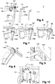
- FIGS. Figures 6 to 10 illustrate a first embodiment of the invention.
- FIGS. Figures 6 to 10 illustrate a second embodiment of the invention.
- Reference numbers of Figures 3 to 5 are used at Figures 6 to 16 for identical or corresponding elements, these numbers being however increased by 100 for the first embodiment illustrated in FIGS. Figures 6 to 10 , and 200 for the second embodiment illustrated in Figures 11 to 16 .
- Specific reference numbers are however used for the specific elements, these numbers being between 100 and 200 for the first mode and between 200 and 300 for the second mode.
- the figure 6 illustrates the principle of the first embodiment of the invention.
- the image on the left of the figure 6 illustrates the right portion of the deformable front structure 102, according to the invention, in the deformed state. It can be seen that it comprises an arm 118 supported by the power unit 112 (not shown) near its alternator 120.
- This arm 118 extends substantially transversely, that is to say in a direction perpendicular to the longitudinal axis of the vehicle, and comes into contact with the front end of the right longitudinal structural section 108b.
- This arm is configured to exert a force directed transversely outwards on the front portion 116b of longitudinal section 108b so as to promote its outward spill.
- This distortion is illustrated in the central image of the figure 6 .
- This image represents the profile alone and shows schematically the cant deformation of the front portion 116b, able to promote shear and thus the deformation of the profile.
- the image on the right of the figure 6 illustrates the neutral fiber of the profile of the central image.
- the three images of the figure 7 illustrate different stages of deformation of the structure of the figure 6 .
- the image on the left illustrates the structure before deformation. It can be observed that the arm 118 extends in a direction having a majority component according to y and a minority component along x. It extends from the fixing zone of the alternator towards the front and the outside of the vehicle to the rear face of the mounting plate 114 at the head of the longitudinal profile 108b.
- the central image illustrates the structure at an intermediate stage of deformation during a full recovery frontal collision in accordance with the figure 2 .
- the transverse beam before 104 has moved backwards, compressing the deformable section 106.
- the image on the right illustrates the structure at the end of the deformation.
- the front portion 116b of the right longitudinal structural section 108b has deformed in shear due to the outward force exerted by the arm 118.
- the latter has pivoted backwards relative to its attachment to the powertrain.
- This image shows the advantageous deformation of the front portion 116b in the context of such a shock, able to absorb more energy.
- the figure 8 illustrates the longitudinal longitudinal structural section 108a at the end of the deformation of the structure during a total recovery frontal collision in accordance with the figure 2 .
- the front portion 116a carried by the left longitudinal profile 108a is also deformed by shearing. This phenomenon is a consequence of the external spill of the right front portion 116b.
- the neutral fiber of the structure 2 is not deformed as "a bow that stretches" illustrated in the figure 5 , but is shear deformed:
- the first shear is triggered by the right-hand arm as described in relation to the figure 7 . It induces a second shear on the left side, shown schematically to the left of the image of the figure 8 by a neutral fiber sheared in the portion 116a of the profile.
- the transverse beam 4 slightly curved as described in connection with the figure 3 is seen straight after deformation and thus elongated in the transverse direction of the vehicle. This elongation of the beam 104 is facilitated by the shearing of the left section 108a which frees the possibility of a transverse displacement towards the outside of the fixing plate 114.
- the off-axis deformation of the section 108a therefore has induced better deceleration characteristics than those obtained by the in-line deformation.
- the arm on the right does not come into contact with the structure. This means that in the event of a frontal collision with partial recovery, as shown in figure 1 , the left side of the structure always retains an energy absorption capacity unchanged and able to meet the conditions of the test.
- the figure 9 is a detail view in perspective of the end of the deformation arm of the structure of Figures 6 and 7 .
- the end of the arm comprises a bearing plate 122 forming an angle close to a right angle, so as to fit the lateral face of the profile 108b and the adjacent rear face of the plate 114.
- the end of the arm is at a distance from the plate and the profile, such as for example at a distance of between 1 mm and 20 mm, more preferably between 5 mm and 15 mm.
- the arm 118 is preferably a generally rectilinear profile. It may, however, be slightly curved or bent according to various parameters such as congestion and / or buckling resistance.
- the profile of the arm is preferably metal, such as steel or aluminum.
- the figure 10 illustrates the zone of attachment of the support 124 of alternator 120 on the engine block 112.
- the arm can then quite easily be fixed by means including a bracket or mounting plate which is then fixed to the block via the fixing screws of the support 124.
- the figure 11 illustrates the principle of the second embodiment of the invention.
- the image on the left of the figure 11 illustrates the right portion of the front structure deformable 202, according to the invention, in the deformed state.
- the device 202 comprises an arm 218 extending substantially longitudinally from an anchor point on the power train 212, in this case a lateral portion 224, towards the rear face of the fixing plate 214 at the head of the section 208b. It can be observed that in the deformed state, the arm exerts a force substantially directed forwardly to the left of the plate 214, thus preventing it from pivoting as has been described in connection with the figure 5 . By preventing or limiting this pivoting, the deformation of the front portion 216b of the section 208b to the outside is thus favored.
- the central image of the figure 11 illustrates the single profile 208b, more particularly its deformation in cant and shear due to the influence of the arm 218 on the plate 214.
- the image on the right of the figure 11 illustrates the neutral fiber of the profile of the central image.
- the three images of the figure 12 illustrate different stages of deformation of the structure of the figure 11 .
- the image on the left illustrates the structure before deformation. It can be seen that the arm 218 extends in a direction having a majority component along x and a minority component along y. It extends from a side zone of the engine, close to the fixing of the alternator, towards the front and the outside of the vehicle to the rear face of the mounting plate 114 at the head of the longitudinal profile 108b.
- the central image illustrates the structure at an intermediate stage of deformation during a full recovery frontal collision in accordance with the figure 2 .
- the transverse beam before 204 has moved backwards, compressing the deformable section 206.
- the image on the right illustrates the structure at the end of the deformation.
- the front portion 216b of the right longitudinal structural section 208b has shear deformed due to the forward force exerted by the arm 218.
- the latter has rotated and / or deformed in bending outwards by compared to its attachment to the powertrain.
- This image shows the advantageous deformation of the front portion 216b in the context of such a shock, able to absorb more energy.
- the figure 13 illustrates the longitudinal longitudinal structural section 208a at the end of the deformation of the structure during a total recovery frontal collision in accordance with the figure 2 .
- the front portion 216a carried by the longitudinal longitudinal section 208a is also deformed by shearing. This phenomenon is a consequence of the external spill of the right front portion 216b in the same manner as has been described in connection with the figure 8 illustrating the distortion of the left structure according to the first embodiment.
- the off-axis deformation of the section 208a therefore has induces better deceleration characteristics than those obtained by the deformation in line.
- the arm on the right does not come into contact with the structure. This means that in the event of a frontal collision with partial recovery, as shown in figure 1 , the left side of the structure always retains an energy absorption capacity unchanged and able to meet the conditions of the test.
- the figure 14 is a detail view in perspective of the end of the deformation arm of the structure of Figures 11 and 12 .
- the end of the arm comprises a bearing plate 222 forming an angle close to a right angle, so as to match the lateral face of the section 208b and the adjacent rear face of the plate 214.
- the end of the arm is at a distance from the plate and the profile, such as for example at a distance of between 1 mm and 20 mm, more preferably between 5 mm and 15 mm.
- the figure 15 is a detail view of the front side of the power train, on the right side. It can identify the alternator 220 and a support 224 belt tensioner roller of the alternator. The zone of attachment of this support to the engine block may constitute an interesting anchor point for the arm 218.
- the figure 16 illustrates the powertrain 212 and a fastener 226 of said group to the vehicle structure. This piece can be adapted to support the arm 218 as shown in the figure.
- the arm 218 is preferably a profile generally straight. It may, however, be slightly curved or curved, it is preferably metallic, such as steel or aluminum.
Landscapes
- Engineering & Computer Science (AREA)
- Mechanical Engineering (AREA)
- Chemical & Material Sciences (AREA)
- Combustion & Propulsion (AREA)
- Transportation (AREA)
- Body Structure For Vehicles (AREA)
- Vibration Dampers (AREA)
Claims (10)
- Kraftfahrzeug-Frontstruktur (102; 202), umfassend:- zwei Längsstrukturprofile (108a, 108b; 208a, 208b), die sich im Wesentlichen parallel zu der Vorderseite des Fahrzeugs erstrecken, mit Befestigungsplatten (114; 214) an ihren vorderen Enden;- ein Antriebsaggregat (112; 212), das zwischen den zwei Längsstrukturprofilen (108a, 108b; 208a, 208b) angeordnet ist;- zwei verformbare Profile (106; 206), die sich jeweils in der vorderen Verlängerung der Strukturprofile (108a, 108b; 208a, 208b) erstrecken und an den Befestigungsplatten (114; 214) der Profile befestigt sind;- einen Querträger (104; 204), der an den vorderen Enden der verformbaren Profile (106; 206) befestigt ist;dadurch gekennzeichnet, dass sie außerdem Folgendes umfasst:einen Arm (18; 218), der an dem Antriebsaggregat (112; 212) befestigt ist und sich im Wesentlichen quer oder längs bis zu der Rückseite der Befestigungsplatte (114; 214) eines (108b; 208b) der zwei Strukturprofile (108a, 108b; 208a, 208b) derart erstreckt, dass auf die Platte (114, 214) eine Längs- und/oder Querkraft ausgeübt wird, die geeignet ist, um eine seitliche Verformung nach außen des vorderen Endes (116b; 216b) des Strukturprofils (108b; 208b) im Fall eines Aufpralls auf dem Querträger (104; 204) zu begünstigen.
- Frontstruktur (102; 202) nach Anspruch 1, dadurch gekennzeichnet, dass das Ende des Arms (118; 218) gegenüber der Rückseite der Platte (114, 214) von der Platte vor dem Aufprall bevorzugt um einen Abstand zwischen 1 mm und 20 mm, bevorzugter zwischen 5 mm und 15 mm beabstandet ist.
- Frontstruktur (102; 202) nach einem der Ansprüche 1 und 2, dadurch gekennzeichnet, dass das andere (108a, 208a) der zwei Strukturprofile (108a, 108b; 208a, 208b) keinen Arm an dem Antriebsaggregat befestigt hat und sich bis zu der Befestigungsplatte des anderen Profils erstreckt, wobei das Profil (108a; 208) bevorzugt auf der Fahrerseite des Fahrzeugs liegt.
- Frontstruktur (102; 202) nach einem der Ansprüche 1 bis 3, dadurch gekennzeichnet, dass der Arm (118, 218) ein im Allgemeinen geradliniges Profil ist, dessen Ende gegenüber der Rückseite der Platte (114; 214) des Strukturprofils (108b; 208b) eine Auflagesohle (122, 222) umfasst, wobei die Sohle bevorzugt einen Winkel zwischen 70° und 110°, bevorzugt zwischen 80 und 100° bildet, so dass sie sich an den von der Platte gebildeten Ansatz legt.
- Frontstruktur (102; 202) nach einem der Ansprüche 1 bis 4, dadurch gekennzeichnet, dass der Arm (118; 218) an einer seitlichen Zone des Antriebsaggregats (112; 212) auf der Seite des Strukturprofils, mit dem er zusammenwirken soll, befestigt ist.
- Frontstruktur (102) nach einem der Ansprüche 1 bis 5, dadurch gekennzeichnet, dass sich der Arm (118) entlang einer mittleren Richtung erstreckt, deren Hauptkomponente zu der Längsachse des Fahrzeugs senkrecht ist und an einer seitlichen vorderen Zone des Antriebsaggregats (112), bevorzugt an einer Befestigungszone der Lichtmaschine (120), des Aggregats befestigt ist.
- Frontstruktur (102) nach Anspruch 6, dadurch gekennzeichnet, dass die mittlere Richtung, entlang welcher sich der Arm (118) erstreckt, eine Längskomponente umfasst, die derart nach vorn gerichtet ist, dass sie es dem Arm erlaubt, in Bezug auf seine Befestigung an dem Antriebsaggregat (112) bei dem Aufprall nach hinten zu schwenken.
- Frontstruktur (202) nach einem der Ansprüche 1 bis 5, dadurch gekennzeichnet, dass sich der Arm (218) entlang einer Richtung erstreckt, deren Hauptkomponente in der Längsachse des Fahrzeugs liegt, und dass er an einer seitlichen Zone des Antriebsaggregats (212), bevorzugt an einer Befestigungszone (226) des Aggregats an der Karosserie des Fahrzeugs, und/oder an einer Befestigungszone (224) eines Riemenspannrollenträgers des Aggregats befestigt ist.
- Frontstruktur (202) nach Anspruch 8, dadurch gekennzeichnet, dass die mittlere Richtung, entlang welcher sich der Arm (218) erstreckt, eine Komponente senkrecht zu der Längsachse des Fahrzeugs umfasst, die derart nach außen gerichtet ist, dass sie es dem Arm erlaubt, in Bezug auf seine Befestigung an dem Antriebsaggregat (212) bei dem Aufprall seitlich zur Außenseite des Fahrzeugs zu schwenken.
- Frontstruktur (102; 202) nach einem der Ansprüche 1 bis 9, dadurch gekennzeichnet, dass der Arm (118; 218) auskragend an dem Antriebsaggregat (112; 212) befestigt ist.
Applications Claiming Priority (2)
| Application Number | Priority Date | Filing Date | Title |
|---|---|---|---|
| FR1359765A FR3011524B1 (fr) | 2013-10-09 | 2013-10-09 | Vehicule automobile avec bras de deformation d’un des brancards en cas d’impact avant |
| PCT/FR2014/052401 WO2015052401A1 (fr) | 2013-10-09 | 2014-09-25 | Vehicule automobile avec bras de deformation d'un des brancards en cas d'impact avant |
Publications (2)
| Publication Number | Publication Date |
|---|---|
| EP3055191A1 EP3055191A1 (de) | 2016-08-17 |
| EP3055191B1 true EP3055191B1 (de) | 2018-02-21 |
Family
ID=49998411
Family Applications (1)
| Application Number | Title | Priority Date | Filing Date |
|---|---|---|---|
| EP14793218.0A Active EP3055191B1 (de) | 2013-10-09 | 2014-09-25 | Kraftfahrzeug mit bügel zum verformen einer der seitenleisten bei einem frontalaufprall |
Country Status (4)
| Country | Link |
|---|---|
| EP (1) | EP3055191B1 (de) |
| CN (1) | CN105612098B (de) |
| FR (1) | FR3011524B1 (de) |
| WO (1) | WO2015052401A1 (de) |
Cited By (1)
| Publication number | Priority date | Publication date | Assignee | Title |
|---|---|---|---|---|
| FR3141116A1 (fr) * | 2022-10-25 | 2024-04-26 | Psa Automobiles Sa | ensemble de renfort frontal pour véhicule automobile |
Families Citing this family (2)
| Publication number | Priority date | Publication date | Assignee | Title |
|---|---|---|---|---|
| FR3124999A1 (fr) * | 2021-07-12 | 2023-01-13 | Psa Automobiles Sa | Élément structurel de véhicule terrestre à zone d’absorption adaptée aux chocs de faible intensité |
| FR3127742A1 (fr) * | 2021-10-05 | 2023-04-07 | Psa Automobiles Sa | Structure avant de véhicule automobile avec reprise en choc frontal d’effort latéral par le groupe motopropulseur |
Family Cites Families (10)
| Publication number | Priority date | Publication date | Assignee | Title |
|---|---|---|---|---|
| DE3710808A1 (de) | 1987-03-31 | 1988-10-20 | Daimler Benz Ag | Abstuetzung von energieabsorbierend deformierten karosseriestrukturen an einem elastisch gelagerten frontmotor von kraftfahrzeugen |
| DE4313785C2 (de) | 1993-04-27 | 1995-10-26 | Daimler Benz Ag | Kraftfahrzeug mit einer zwei Längsträger aufweisenden Tragstruktur |
| FR2887211B1 (fr) * | 2005-06-20 | 2007-09-07 | Vallourec Vitry | Voie basse guidee pour avant de vehicule automobile |
| EP2284042B1 (de) * | 2005-08-25 | 2019-03-20 | WESTFALIA - Automotive GmbH | Trägeranordnung für ein Kraftfahrzeug und Halteranordnung dafür |
| JP2007203807A (ja) * | 2006-01-31 | 2007-08-16 | Honda Motor Co Ltd | 自動車の衝突エネルギー吸収構造 |
| JP4484920B2 (ja) * | 2007-12-04 | 2010-06-16 | 本田技研工業株式会社 | 車体前部構造 |
| EP2138356A1 (de) * | 2008-06-26 | 2009-12-30 | Mazda Motor Corporation | Vorderwagenstruktur, damit ausgestattetes Fahrzeug und Bereitstellungsverfahren dafür |
| DE102010009094A1 (de) * | 2010-02-24 | 2010-09-16 | Daimler Ag | Verbindungsanordnung |
| CN102490788B (zh) * | 2011-11-28 | 2014-09-17 | 浙江吉利汽车研究院有限公司 | 一种可伸缩的纵梁和设置有该可伸缩纵梁的汽车 |
| US8267445B1 (en) * | 2012-02-06 | 2012-09-18 | Ford Global Technologies, Llc | Inertia-locking reactive bumper for motor vehicle |
-
2013
- 2013-10-09 FR FR1359765A patent/FR3011524B1/fr active Active
-
2014
- 2014-09-25 CN CN201480055453.2A patent/CN105612098B/zh not_active Expired - Fee Related
- 2014-09-25 WO PCT/FR2014/052401 patent/WO2015052401A1/fr not_active Ceased
- 2014-09-25 EP EP14793218.0A patent/EP3055191B1/de active Active
Cited By (1)
| Publication number | Priority date | Publication date | Assignee | Title |
|---|---|---|---|---|
| FR3141116A1 (fr) * | 2022-10-25 | 2024-04-26 | Psa Automobiles Sa | ensemble de renfort frontal pour véhicule automobile |
Also Published As
| Publication number | Publication date |
|---|---|
| FR3011524A1 (fr) | 2015-04-10 |
| EP3055191A1 (de) | 2016-08-17 |
| FR3011524B1 (fr) | 2015-11-20 |
| CN105612098A (zh) | 2016-05-25 |
| WO2015052401A1 (fr) | 2015-04-16 |
| CN105612098B (zh) | 2017-10-03 |
Similar Documents
| Publication | Publication Date | Title |
|---|---|---|
| EP1893469B1 (de) | Geführter unterbereich der front eines automobils | |
| EP2222538B1 (de) | Träger für ein fahrzeugarmaturenbrett | |
| EP3177506B1 (de) | Fussboden mit querträger mit einem kompressiv verformbaren teil | |
| FR2928877A1 (fr) | Structure de montage de groupe motopropulseur d'un vehicule electrique. | |
| EP3027487B1 (de) | Stossdämpfender vorrichtung für kraftfahrzeug | |
| EP3140176B1 (de) | Kraftfahrzeug mit crashbox mit planmässiger bremsung bei einem frontalaufprall | |
| EP3844050A1 (de) | Fahrzeug mit einer intelligenten frontalaufpralldämpfungsvorrichtung | |
| WO2015052401A1 (fr) | Vehicule automobile avec bras de deformation d'un des brancards en cas d'impact avant | |
| FR3031950A1 (fr) | Impacteur a cinematique active pour choc frontal de vehicule automobile compatible d’un vehicule rehausse | |
| EP2999617B1 (de) | Schnittstelle zur befestigung eines fahrzeugbodens und eines motorträgers aneinander zur abschwächung des gesetzes der entschleunigung während eines frontaufpralls | |
| FR2729980A1 (fr) | Glissiere de securite routiere a dispositif absorbeur de chocs | |
| FR2867730A1 (fr) | Systeme de pare-chocs compose d'une traverse ayant une section transversale trapezoidale et de deux absorbeurs de chocs | |
| FR2706961A1 (en) | Device for absorbing impact energy, especially for a motor vehicle | |
| EP4284667A1 (de) | Kraftfahrzeugstruktur | |
| EP4301629B1 (de) | Stossfängerverstärkungsschnittstellenhalterung für ein kraftfahrzeug | |
| WO2014154968A1 (fr) | Palier de fixation d'une barre anti-dévers au chasisis d'un véhicule automobile | |
| EP2493748B1 (de) | Armaturenbrettstruktur für ein motorfahrzeug und herstellungsverfahren dafür | |
| EP3856617B1 (de) | Batterieverstärkung für einen heckaufprall bei hoher geschwindigkeit | |
| FR3081423A1 (fr) | Vehicule avec dispositif d’absorption a surface d’impact augmentant durant un choc. | |
| FR3016576A1 (fr) | Facade avant de vehicule automobile avec galbe actif en cas de choc. | |
| FR3038276A1 (fr) | Dispositif de montage d'une pedale dans un vehicule automobile | |
| EP4613612A1 (de) | Lenksäule für ein kraftfahrzeug | |
| EP4037957A1 (de) | Seitenaufpralldämpfer für ein kraftfahrzeug | |
| WO2019048636A1 (fr) | Diffuseur arrière mobile à engrenage | |
| EP1647468A1 (de) | Trägerteil eines Fahrzeugs |
Legal Events
| Date | Code | Title | Description |
|---|---|---|---|
| PUAI | Public reference made under article 153(3) epc to a published international application that has entered the european phase |
Free format text: ORIGINAL CODE: 0009012 |
|
| 17P | Request for examination filed |
Effective date: 20160311 |
|
| AK | Designated contracting states |
Kind code of ref document: A1 Designated state(s): AL AT BE BG CH CY CZ DE DK EE ES FI FR GB GR HR HU IE IS IT LI LT LU LV MC MK MT NL NO PL PT RO RS SE SI SK SM TR |
|
| AX | Request for extension of the european patent |
Extension state: BA ME |
|
| DAX | Request for extension of the european patent (deleted) | ||
| RAP1 | Party data changed (applicant data changed or rights of an application transferred) |
Owner name: PSA AUTOMOBILES SA |
|
| GRAP | Despatch of communication of intention to grant a patent |
Free format text: ORIGINAL CODE: EPIDOSNIGR1 |
|
| INTG | Intention to grant announced |
Effective date: 20170915 |
|
| GRAS | Grant fee paid |
Free format text: ORIGINAL CODE: EPIDOSNIGR3 |
|
| GRAA | (expected) grant |
Free format text: ORIGINAL CODE: 0009210 |
|
| AK | Designated contracting states |
Kind code of ref document: B1 Designated state(s): AL AT BE BG CH CY CZ DE DK EE ES FI FR GB GR HR HU IE IS IT LI LT LU LV MC MK MT NL NO PL PT RO RS SE SI SK SM TR |
|
| REG | Reference to a national code |
Ref country code: GB Ref legal event code: FG4D Free format text: NOT ENGLISH |
|
| REG | Reference to a national code |
Ref country code: CH Ref legal event code: EP |
|
| REG | Reference to a national code |
Ref country code: AT Ref legal event code: REF Ref document number: 971392 Country of ref document: AT Kind code of ref document: T Effective date: 20180315 |
|
| REG | Reference to a national code |
Ref country code: IE Ref legal event code: FG4D Free format text: LANGUAGE OF EP DOCUMENT: FRENCH |
|
| REG | Reference to a national code |
Ref country code: DE Ref legal event code: R096 Ref document number: 602014021345 Country of ref document: DE |
|
| REG | Reference to a national code |
Ref country code: DE Ref legal event code: R084 Ref document number: 602014021345 Country of ref document: DE |
|
| REG | Reference to a national code |
Ref country code: GB Ref legal event code: 746 Effective date: 20180322 |
|
| REG | Reference to a national code |
Ref country code: NL Ref legal event code: MP Effective date: 20180221 |
|
| REG | Reference to a national code |
Ref country code: LT Ref legal event code: MG4D |
|
| REG | Reference to a national code |
Ref country code: AT Ref legal event code: MK05 Ref document number: 971392 Country of ref document: AT Kind code of ref document: T Effective date: 20180221 |
|
| PG25 | Lapsed in a contracting state [announced via postgrant information from national office to epo] |
Ref country code: FI Free format text: LAPSE BECAUSE OF FAILURE TO SUBMIT A TRANSLATION OF THE DESCRIPTION OR TO PAY THE FEE WITHIN THE PRESCRIBED TIME-LIMIT Effective date: 20180221 Ref country code: NO Free format text: LAPSE BECAUSE OF FAILURE TO SUBMIT A TRANSLATION OF THE DESCRIPTION OR TO PAY THE FEE WITHIN THE PRESCRIBED TIME-LIMIT Effective date: 20180521 Ref country code: CY Free format text: LAPSE BECAUSE OF FAILURE TO SUBMIT A TRANSLATION OF THE DESCRIPTION OR TO PAY THE FEE WITHIN THE PRESCRIBED TIME-LIMIT Effective date: 20180221 Ref country code: NL Free format text: LAPSE BECAUSE OF FAILURE TO SUBMIT A TRANSLATION OF THE DESCRIPTION OR TO PAY THE FEE WITHIN THE PRESCRIBED TIME-LIMIT Effective date: 20180221 Ref country code: LT Free format text: LAPSE BECAUSE OF FAILURE TO SUBMIT A TRANSLATION OF THE DESCRIPTION OR TO PAY THE FEE WITHIN THE PRESCRIBED TIME-LIMIT Effective date: 20180221 Ref country code: HR Free format text: LAPSE BECAUSE OF FAILURE TO SUBMIT A TRANSLATION OF THE DESCRIPTION OR TO PAY THE FEE WITHIN THE PRESCRIBED TIME-LIMIT Effective date: 20180221 Ref country code: ES Free format text: LAPSE BECAUSE OF FAILURE TO SUBMIT A TRANSLATION OF THE DESCRIPTION OR TO PAY THE FEE WITHIN THE PRESCRIBED TIME-LIMIT Effective date: 20180221 |
|
| REG | Reference to a national code |
Ref country code: FR Ref legal event code: PLFP Year of fee payment: 5 |
|
| PG25 | Lapsed in a contracting state [announced via postgrant information from national office to epo] |
Ref country code: GR Free format text: LAPSE BECAUSE OF FAILURE TO SUBMIT A TRANSLATION OF THE DESCRIPTION OR TO PAY THE FEE WITHIN THE PRESCRIBED TIME-LIMIT Effective date: 20180522 Ref country code: RS Free format text: LAPSE BECAUSE OF FAILURE TO SUBMIT A TRANSLATION OF THE DESCRIPTION OR TO PAY THE FEE WITHIN THE PRESCRIBED TIME-LIMIT Effective date: 20180221 Ref country code: AT Free format text: LAPSE BECAUSE OF FAILURE TO SUBMIT A TRANSLATION OF THE DESCRIPTION OR TO PAY THE FEE WITHIN THE PRESCRIBED TIME-LIMIT Effective date: 20180221 Ref country code: BG Free format text: LAPSE BECAUSE OF FAILURE TO SUBMIT A TRANSLATION OF THE DESCRIPTION OR TO PAY THE FEE WITHIN THE PRESCRIBED TIME-LIMIT Effective date: 20180521 Ref country code: LV Free format text: LAPSE BECAUSE OF FAILURE TO SUBMIT A TRANSLATION OF THE DESCRIPTION OR TO PAY THE FEE WITHIN THE PRESCRIBED TIME-LIMIT Effective date: 20180221 Ref country code: SE Free format text: LAPSE BECAUSE OF FAILURE TO SUBMIT A TRANSLATION OF THE DESCRIPTION OR TO PAY THE FEE WITHIN THE PRESCRIBED TIME-LIMIT Effective date: 20180221 |
|
| PG25 | Lapsed in a contracting state [announced via postgrant information from national office to epo] |
Ref country code: MT Free format text: LAPSE BECAUSE OF FAILURE TO SUBMIT A TRANSLATION OF THE DESCRIPTION OR TO PAY THE FEE WITHIN THE PRESCRIBED TIME-LIMIT Effective date: 20180221 |
|
| PG25 | Lapsed in a contracting state [announced via postgrant information from national office to epo] |
Ref country code: PL Free format text: LAPSE BECAUSE OF FAILURE TO SUBMIT A TRANSLATION OF THE DESCRIPTION OR TO PAY THE FEE WITHIN THE PRESCRIBED TIME-LIMIT Effective date: 20180221 Ref country code: EE Free format text: LAPSE BECAUSE OF FAILURE TO SUBMIT A TRANSLATION OF THE DESCRIPTION OR TO PAY THE FEE WITHIN THE PRESCRIBED TIME-LIMIT Effective date: 20180221 Ref country code: RO Free format text: LAPSE BECAUSE OF FAILURE TO SUBMIT A TRANSLATION OF THE DESCRIPTION OR TO PAY THE FEE WITHIN THE PRESCRIBED TIME-LIMIT Effective date: 20180221 Ref country code: IT Free format text: LAPSE BECAUSE OF FAILURE TO SUBMIT A TRANSLATION OF THE DESCRIPTION OR TO PAY THE FEE WITHIN THE PRESCRIBED TIME-LIMIT Effective date: 20180221 Ref country code: AL Free format text: LAPSE BECAUSE OF FAILURE TO SUBMIT A TRANSLATION OF THE DESCRIPTION OR TO PAY THE FEE WITHIN THE PRESCRIBED TIME-LIMIT Effective date: 20180221 |
|
| REG | Reference to a national code |
Ref country code: DE Ref legal event code: R097 Ref document number: 602014021345 Country of ref document: DE |
|
| PG25 | Lapsed in a contracting state [announced via postgrant information from national office to epo] |
Ref country code: SK Free format text: LAPSE BECAUSE OF FAILURE TO SUBMIT A TRANSLATION OF THE DESCRIPTION OR TO PAY THE FEE WITHIN THE PRESCRIBED TIME-LIMIT Effective date: 20180221 Ref country code: DK Free format text: LAPSE BECAUSE OF FAILURE TO SUBMIT A TRANSLATION OF THE DESCRIPTION OR TO PAY THE FEE WITHIN THE PRESCRIBED TIME-LIMIT Effective date: 20180221 Ref country code: SM Free format text: LAPSE BECAUSE OF FAILURE TO SUBMIT A TRANSLATION OF THE DESCRIPTION OR TO PAY THE FEE WITHIN THE PRESCRIBED TIME-LIMIT Effective date: 20180221 Ref country code: CZ Free format text: LAPSE BECAUSE OF FAILURE TO SUBMIT A TRANSLATION OF THE DESCRIPTION OR TO PAY THE FEE WITHIN THE PRESCRIBED TIME-LIMIT Effective date: 20180221 |
|
| PLBE | No opposition filed within time limit |
Free format text: ORIGINAL CODE: 0009261 |
|
| STAA | Information on the status of an ep patent application or granted ep patent |
Free format text: STATUS: NO OPPOSITION FILED WITHIN TIME LIMIT |
|
| 26N | No opposition filed |
Effective date: 20181122 |
|
| PG25 | Lapsed in a contracting state [announced via postgrant information from national office to epo] |
Ref country code: SI Free format text: LAPSE BECAUSE OF FAILURE TO SUBMIT A TRANSLATION OF THE DESCRIPTION OR TO PAY THE FEE WITHIN THE PRESCRIBED TIME-LIMIT Effective date: 20180221 |
|
| PG25 | Lapsed in a contracting state [announced via postgrant information from national office to epo] |
Ref country code: MC Free format text: LAPSE BECAUSE OF FAILURE TO SUBMIT A TRANSLATION OF THE DESCRIPTION OR TO PAY THE FEE WITHIN THE PRESCRIBED TIME-LIMIT Effective date: 20180221 |
|
| REG | Reference to a national code |
Ref country code: CH Ref legal event code: PL |
|
| REG | Reference to a national code |
Ref country code: BE Ref legal event code: MM Effective date: 20180930 |
|
| REG | Reference to a national code |
Ref country code: IE Ref legal event code: MM4A |
|
| PG25 | Lapsed in a contracting state [announced via postgrant information from national office to epo] |
Ref country code: LU Free format text: LAPSE BECAUSE OF NON-PAYMENT OF DUE FEES Effective date: 20180925 |
|
| PG25 | Lapsed in a contracting state [announced via postgrant information from national office to epo] |
Ref country code: IE Free format text: LAPSE BECAUSE OF NON-PAYMENT OF DUE FEES Effective date: 20180925 |
|
| PG25 | Lapsed in a contracting state [announced via postgrant information from national office to epo] |
Ref country code: LI Free format text: LAPSE BECAUSE OF NON-PAYMENT OF DUE FEES Effective date: 20180930 Ref country code: BE Free format text: LAPSE BECAUSE OF NON-PAYMENT OF DUE FEES Effective date: 20180930 Ref country code: CH Free format text: LAPSE BECAUSE OF NON-PAYMENT OF DUE FEES Effective date: 20180930 |
|
| PG25 | Lapsed in a contracting state [announced via postgrant information from national office to epo] |
Ref country code: TR Free format text: LAPSE BECAUSE OF FAILURE TO SUBMIT A TRANSLATION OF THE DESCRIPTION OR TO PAY THE FEE WITHIN THE PRESCRIBED TIME-LIMIT Effective date: 20180221 |
|
| PG25 | Lapsed in a contracting state [announced via postgrant information from national office to epo] |
Ref country code: PT Free format text: LAPSE BECAUSE OF FAILURE TO SUBMIT A TRANSLATION OF THE DESCRIPTION OR TO PAY THE FEE WITHIN THE PRESCRIBED TIME-LIMIT Effective date: 20180221 |
|
| PG25 | Lapsed in a contracting state [announced via postgrant information from national office to epo] |
Ref country code: MK Free format text: LAPSE BECAUSE OF NON-PAYMENT OF DUE FEES Effective date: 20180221 Ref country code: HU Free format text: LAPSE BECAUSE OF FAILURE TO SUBMIT A TRANSLATION OF THE DESCRIPTION OR TO PAY THE FEE WITHIN THE PRESCRIBED TIME-LIMIT; INVALID AB INITIO Effective date: 20140925 |
|
| PG25 | Lapsed in a contracting state [announced via postgrant information from national office to epo] |
Ref country code: IS Free format text: LAPSE BECAUSE OF FAILURE TO SUBMIT A TRANSLATION OF THE DESCRIPTION OR TO PAY THE FEE WITHIN THE PRESCRIBED TIME-LIMIT Effective date: 20180621 |
|
| REG | Reference to a national code |
Ref country code: DE Ref legal event code: R081 Ref document number: 602014021345 Country of ref document: DE Owner name: STELLANTIS AUTO SAS, FR Free format text: FORMER OWNER: PSA AUTOMOBILES SA, POISSY, FR |
|
| PGFP | Annual fee paid to national office [announced via postgrant information from national office to epo] |
Ref country code: GB Payment date: 20240820 Year of fee payment: 11 |
|
| PGFP | Annual fee paid to national office [announced via postgrant information from national office to epo] |
Ref country code: DE Payment date: 20250820 Year of fee payment: 12 |
|
| PGFP | Annual fee paid to national office [announced via postgrant information from national office to epo] |
Ref country code: FR Payment date: 20250820 Year of fee payment: 12 |
|
| GBPC | Gb: european patent ceased through non-payment of renewal fee |
Effective date: 20250925 |
|
| PG25 | Lapsed in a contracting state [announced via postgrant information from national office to epo] |
Ref country code: GB Free format text: LAPSE BECAUSE OF NON-PAYMENT OF DUE FEES Effective date: 20250925 |