EP3140176B1 - Kraftfahrzeug mit crashbox mit planmässiger bremsung bei einem frontalaufprall - Google Patents
Kraftfahrzeug mit crashbox mit planmässiger bremsung bei einem frontalaufprall Download PDFInfo
- Publication number
- EP3140176B1 EP3140176B1 EP15715792.6A EP15715792A EP3140176B1 EP 3140176 B1 EP3140176 B1 EP 3140176B1 EP 15715792 A EP15715792 A EP 15715792A EP 3140176 B1 EP3140176 B1 EP 3140176B1
- Authority
- EP
- European Patent Office
- Prior art keywords
- deformable
- oblong
- profile
- front structure
- profiles
- Prior art date
- Legal status (The legal status is an assumption and is not a legal conclusion. Google has not performed a legal analysis and makes no representation as to the accuracy of the status listed.)
- Active
Links
Images

Classifications
-
- B—PERFORMING OPERATIONS; TRANSPORTING
- B62—LAND VEHICLES FOR TRAVELLING OTHERWISE THAN ON RAILS
- B62D—MOTOR VEHICLES; TRAILERS
- B62D21/00—Understructures, i.e. chassis frame on which a vehicle body may be mounted
- B62D21/15—Understructures, i.e. chassis frame on which a vehicle body may be mounted having impact absorbing means, e.g. a frame designed to permanently or temporarily change shape or dimension upon impact with another body
- B62D21/152—Front or rear frames
-
- B—PERFORMING OPERATIONS; TRANSPORTING
- B62—LAND VEHICLES FOR TRAVELLING OTHERWISE THAN ON RAILS
- B62D—MOTOR VEHICLES; TRAILERS
- B62D25/00—Superstructure or monocoque structure sub-units; Parts or details thereof not otherwise provided for
- B62D25/08—Front or rear portions
- B62D25/082—Engine compartments
Definitions
- the invention relates to shock absorption in the front of a motor vehicle. More particularly, the invention relates to a front vehicle structure and to a vehicle adapted to absorb front shocks.
- the document DE 10 2009 053 369 A1 discloses a front structure of a motor vehicle according to the preamble of claim 1.
- a front shock absorber system or device for a vehicle is conventionally constituted by a transverse beam fixed to two sections deformable in compression and commonly called "crashboxes". These deformable profiles may each comprise a mounting plate to the stretcher head of the vehicle structure. Stretchers are the two structural sections extending parallel to each other along the vehicle structure.
- the deformable profiles or "crashboxes" are designed to be deformed by forming folds in the manner of an accordion.
- a front shock absorber for a vehicle must meet many benefits, including frontal impact tests. Among these tests, there is a frontal impact test at 64 km / h with partial overlap against a barrier composed of a complex structure, which represents the "theoretical" deformation of a front block car oncoming. It consists in particular of honeycomb panels.
- the figure 1 illustrates this shock test.
- the protocol is the one currently used by the European New Car Assessment Program (Euro NCAP). This test is to satisfy both the left side and the right side.
- a new frontal impact protocol at 50 km / h and 56 km / h with 100% coverage against a rigid wall is in preparation. It is likely to be introduced in the Euro NCAP protocol by 2015. This test is illustrated in the figure 2 . It is therefore desirable to satisfy these two frontal impact protocols.
- On the occasion of the shock shifted to 40% only one side of the vehicle hits the obstacle and the obstacle is otherwise deformable. Having to absorb all the energy of the Shock on the only side impacted increases the risk of intrusions inside the cockpit on this side.
- the deformation of the barrier filters the deceleration experienced by the vehicle, which can be treated with the occupant restraint means according to the state of the art.
- the object of the invention is to propose a vehicle front shock absorber device which can satisfy the above-mentioned two tests, more particularly the frontal impact test with a 40% overlap on a deformable obstacle and the frontal collision test with overlap. total on rigid obstacle.
- the invention relates to a front structure of a motor vehicle comprising two longitudinal structural sections extending substantially parallel to the front of the vehicle; two deformable sections, extending, respectively, in the extension before the structural sections and fixed at their front end via fastening means; a curved transverse beam fixed at the front ends of the deformable sections, remarkable in that the means for fixing one of the deformable profiles to the corresponding structural profile are configured to allow transverse displacement, outwardly, of the rear end of said profile deformable relative to the front end of the structural section, in the event of impact on the curved beam, so as to generate lateral deformation, outwardly, of the front end of the corresponding structural section.
- the transverse beam comprises a curved central portion protruding longitudinally forwards its lateral parts by at least 20 mm, preferably 40 mm, more preferably 60 mm, more preferably still 80 mm.
- the fastening means of the deformable profile intended to move relative to the corresponding structural section comprise one or more oblong orifices oriented in a transverse direction and a screw engaging said orifice or each of said orifices, respectively.
- the deformable profile intended to move and the corresponding structural section each comprise a fixing plate, the oblong orifice or at least one of the oblong orifices being made in at least one of said fixing plates, the one or more of said fixing plates being preferably made of aluminum.
- the or each screw engaging the or each of the oblong orifices is tightened in a tightening torque so as to allow the displacement of the rear end of the deformable profile during the deformation of the beam curved transverse.
- the or each of the screws has a diameter of 6 mm to 10 mm.
- the or each of the screws is tightened to a tightening torque of between 20 Nm and 40 Nm.
- the oblong orifice or at least one of the oblong orifices is situated at the edge of the plate, at a distance from each of the edges of the plate of less than 5% of the largest dimension of the plate.
- platinum, at least one of the oblong orifices being opening on the edge of the plate.
- the plate of the deformable section comprises four fixing holes, each of the orifices being oblong.
- the plate of the deformable section comprises two fixing holes opening on the edge of the plate.
- the other of the two deformable sections is blank of fixing means configured to allow a transverse outward movement of said profile relative to the corresponding structural section, said section preferably being on the driver's side of the vehicle .
- the front structure further comprises a part arranged between the fixing plates of the deformable profile intended to move and the corresponding structural section, said part preferably being a cross-member support.
- the length of the oblong orifice or of each of the oblong orifices, in the oblong direction is between 1, 5 and 3 times the diameter of the fixing screw.
- the length of the oblong orifice or each of the oblong orifices, in the oblong direction is between 9 mm and 30 mm.
- the oblong orifice or each of the oblong orifices comprises a section portion smaller than the diameter of the fixing screw, said portion extending over at least 30%, preferably at least 50%, of the length of the oblong orifice.
- the lower section portion is advantageously located on the side of the oblong orifice which corresponds to the inner side of the vehicle.
- the lower section portion is of a value between 6mm and 10mm.
- the invention also relates to a motor vehicle, remarkable in that it comprises a front structure according to the invention.
- the measurements of the invention are interesting in that they allow the structure before satisfying the two tests described in the part relating to the prior art, with simple and economical means. They make it possible to maintain the behavior of the driver side in shock shifted on the driver's side.
- the oblong holes do not call into question the vehicle's architectural interfaces or its structure at the level of the shoe.
- the Figures 3 to 5 illustrate the deformation of a conventional deformable front structure of a motor vehicle during a front impact with full recovery or essentially total. More specifically, the figure 3 illustrates the structure in the undeformed state, the figure 4 illustrates the structure in the deformed state following the shock and the figure 5 illustrates the neutral fiber of the deformed structure according to the figure 4 .
- the front structure 2 of a motor vehicle comprises, essentially, a transverse beam before 4, supported at both ends, by two deformable sections (6a, 6b), commonly called “crashboxes".
- deformable sections (6a, 6b)
- the structure 2 also comprises two longitudinal longitudinal structural sections 8a and 8b supporting the deformable sections 6a and 6b and the transverse beam 4. These sections 8a and 8b are commonly called “stretchers”.
- a rear transverse beam 10 connects the two sections 8a and 8b.
- Each of these profiles comprises, at its head or front end, a mounting plate 14, intended to ensure the connection with the deformable sections 6a and 6b.
- the front portions 16a and 16b of the longitudinal structural sections 8a and 8b are also designed to deform or "bunch” by forming folds in the manner of an accordion.
- a power unit 12 is disposed, in this case transversely, between the two longitudinal structural sections 8a and 8b.
- the figure 4 illustrates structure 2 of the figure 3 in the deformed state following a frontal collision with total recovery of the type illustrated in FIG. figure 2 .
- the initially curved front transverse beam 4 is now completely straight and has moved backwards.
- the deformable profiles (“crashboxes") are completely deformed in compression without cant.
- the front portions (16a, 16b) of the longitudinal structural sections (8a, 8b) are also deformed in untolled compression.
- the remainder of the longitudinal structural sections (8a, 8b) remained essentially intact. In other words, it means that almost all of the impact energy is absorbed by the "bunching" of the deformable profiles (6a, 6b) and the front portions (16a, 16b) of the longitudinal structural sections (8a, 6b). , 8b).
- the figure 5 illustrates the neutral fiber of the structure 2 after deformation according to the figure 4 .
- the longitudinal profiles (8a, 8b) tend to bend outwards according to the arrows shown.
- the rotational movements of the fixing plates 14 which maintain their orientation relative to the neutral fiber of the profiles (8a, 8b).
- the transverse beam before 4 is then solicited in traction.
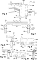
- FIGS. 6 to 12 illustrate the deformation of a front structure 102 of a motor vehicle according to the invention, during a front impact with total or substantially total recovery.
- the figure 6 is a rear three-quarter view of the right deformable profile 106b of the front structure 102 of the vehicle according to the invention.
- the deformable section 106b is shown fixed to the transverse beam 104.
- the attachment means 122 of the deformable section 106b to the corresponding structural section are configured to allow transverse displacement towards the outside of the rear end 120b of said deformable section 106b with respect to the structural section, in case of impact on the curved beam.
- This displacement is intended to generate a deformation in lateral bending, outwardly, of the front end of the corresponding structural section; this displacement will be seen in detail below.
- the fastening means 122 of the deformable section 106b comprise one or more oblong orifices 124 oriented in a transverse direction and a screw 126 engaging said orifice 124 or each of said orifices, respectively.
- the deformable section 106b comprises a fixing plate 128b, the oblong orifice 124 or at least one of the oblong orifices 124 being formed in this fixing plate 128b.
- each of the fixing orifices 124 made in the plate 128b may be an oblong orifice.
- the oblong orifice 124 or at least one of the oblong orifices may be located at the edge 130 of the plate, at a distance from each of the edges of the plate of less than 5% of the greater distance of the plate 128b. At least one of the oblong orifices may be opening.
- the plate 128b comprises four oblong fixing holes, the two holes located on the inside of the vehicle being opening on the edge of the plate.
- the oblong orifice may have a length of between 1.5 and 3 times the diameter of the fixing screw 124.
- the fixing screw 126 may be of a diameter of between 6 mm and 10 mm.
- the oblong orifice 124 may have a length of between 9mm and 30mm.
- the oblong orifice 124 may comprise a portion of section 132 smaller than the diameter of the fixing screw 126, said portion extending over at least 30%, preferably at least 50% of the length of the oblong orifice.
- the lower section portion is advantageously located on the side of the oblong orifice which corresponds to the inner side of the vehicle.
- the figure 7 is a top view of the front structure 102 according to the invention, it is in position facing a frontal collision wall full recovery.
- the transverse beam 104 we can see the transverse beam 104, the deformable profiles (106a, 106b) as well as the front portions (116a, 116b) of the longitudinal structural sections (108a, 108b).
- the deformable section 106b intended to move, is shown on the right in the image; the other 106a of the two deformable sections (106a, 106b) is blank fixing means according to the invention.
- This other section 106a is preferably on the driver's side of the vehicle.
- the deformable section 106b and the corresponding structural section 108b each comprise an attachment plate 128b, the oblong orifice 124 or at least one of the oblong orifices 124 being formed in one or at least one of said plates.
- the oblong holes can be made in the plate of the structural section; in a preferred embodiment, they are exclusively made in the mounting plate of the deformable section.
- Fastening screws (represented by axis trays) are engaged in the fixing holes 124 of the plates 128b.
- the screw or each of the screws engaging the or each of the oblong orifices 124 may be of a diameter of between 6 mm and 10 mm; the screw or each of these screws is tightened to a tightening torque so as to allow the displacement of the deformable section 106b during the deformation of the curved transverse beam 104; this tightening torque can be between 20Nm and 40Nm.
- an additional piece (not shown) may be located in interface between the fastening plates 128b of the deformable sections 106b and structural 108b. This piece can be a cross support front facade of the vehicle.
- the figure 7 has the transverse beam 104 with a central portion 134 curved protruding longitudinally its side portions of at least 20mm. They can exceed 40mm, even 60mm or even 80mm.
- Outwardly facing arrows of the structure 102 illustrate the lateral forces transmitted in the structure in the event of impact before, during the offsetting of the transverse beam.
- FIGs 8 and 10 are views of the straight deformable profile 106b of the front structure 102 of the figure 7 according to a preferred embodiment.
- the views illustrate the beginning and the end, respectively, of the displacement of the rear end 120b of the deformable section 106b with respect to the structural section 108b during the impact of the structure 102 against the full-covering wall seen in relation to FIG. previous.
- FIGS. 9 and 11 are sectional views of the plate 128b of the deformable section 106b at two different stages of its displacement.
- the figure 8 is a view of the deformable profile 106b right of the structure of the figure 7 at the stage of intermediate deformation of the vehicle. We can see the transverse displacement towards the outside of the rear end 120b of the profile 106b with respect to the structural section 108b.
- the figure 9 is a sectional view of the plate 128b of the deformable section 106b at the stage of intermediate deformation described in connection with the figure 8 .
- Two oblong fixing holes 124 are shown with a fixing screw 126 engaged in each of them.
- the oblong orifices 124 comprise in this case a portion of lower section 132 to the diameter of the screw.
- the local deformation of the plate is interesting in that it facilitates the realization of the structure before, in particularly as regards the adjustment of the transverse force threshold from which the plate 128b of the deformable section 106b is intended to move
- the figure 10 is a view of the right deformable profile 106b of the structure 102 of the figure 7 during deformation. It can be seen the transverse displacement towards the outside of the rear end 120b of the deformable section 106b with respect to the structural section 108b. This displacement is much more pronounced than that presented in relation to the figure 8 .
- the deformable profile 106b is presented in part compressed in the longitudinal direction.
- the transverse beam 104 may no longer be curved at this stage of the deformation; the central part of the originally curved beam may be in the same longitudinal plane as its lateral ends.
- the displacement of the rear end 120b of the deformable section 106b aims to release the voltage, seen in relation to the figure 5 of the front structure 102 by "programmed” breaking of the fastening between the right deformable section 106b and the structural section 108b.
- the figure 11 is a sectional view of the plate 128b of the deformable section 106b at the stage of intermediate deformation described in connection with the figure 10 .
- the screw 126 engaged in the oblong opening 124 opening on the edge of the plate 128b may be outside the plate 128 at this stage of displacement of the rear end of the profile.
- the other screw 126, on the right in the image, may be in abutment with the corresponding oblong orifice 124; it can, at this stage, be cut by the displacement of the plate 128b.
- the figure 12 is a view of the right longitudinal structural profile 108b at the end of the deformation of the structure 102 during a total recovery frontal collision in accordance with the figure 7 .
- the front portion 116b of the right longitudinal structural section has deformed in shear due to the shifted force outwardly exerted by the deformable section 106b.
- This image shows the advantageous deformation of the front portion 116b, in the context of such a shock, able to absorb more energy.
Landscapes
- Engineering & Computer Science (AREA)
- Chemical & Material Sciences (AREA)
- Combustion & Propulsion (AREA)
- Transportation (AREA)
- Mechanical Engineering (AREA)
- Body Structure For Vehicles (AREA)
Claims (9)
- Frontstruktur (102) eines Kraftfahrzeugs, die Folgendes umfasst:- zwei Strukturlängsprofile (108a, 108b), die sich im Wesentlichen parallel zu der Frontseite des Fahrzeugs erstrecken;- zwei verformbare Profile (106a, 106b), die sich jeweils in der vorderen Verlängerung der Strukturprofile (108a, 108b) erstrecken und an ihrem Frontende über Befestigungsmittel befestigt sind;- einen gewölbten Querträger (104), der an den Frontenden der verformbaren Profile (106a, 106b) befestigt ist;wobei die Befestigungsmittel (122) eines der verformbaren Profile (106b) an dem entsprechenden Strukturprofil (108b) konfiguriert sind, um eine Querverlagerung nach außen von dem hinteren Ende (120b) des verformbaren Profils (106b) in Bezug auf das Frontende des Strukturprofils (108b) bei einem Aufprall auf dem gewölbten Träger (104) derart zu erlauben, dass eine seitliche Verformung nach außen des Frontendes (116b) des entsprechenden Strukturprofils (108b) bewirkt wird, dadurch gekennzeichnet, dass die Befestigungsmittel (122) des verformbaren Profils (106b), das dazu bestimmt ist, sich in Bezug auf das entsprechende Strukturprofil (108b) zu verlagern, eine oder mehr längliche Öffnungen (124) umfassen, die entlang einer Querrichtung ausgerichtet sind, und eine Schraube (126), die jeweils in die Öffnung (124) oder eine der Öffnungen (124) eingreift.
- Frontstruktur (102) nach Anspruch 1, dadurch gekennzeichnet, dass die oder jede Schraube (126), die in die oder jede längliche Öffnung (124) eingreift, dazu bestimmt ist, gemäß einem Anziehdrehmoment derart angezogen zu werden, dass die Verlagerung des hinteren Endes (120b) des verformbaren Profils (106b) im Laufe der Verformung des gewölbten Querträgers (104) auftritt.
- Frontstruktur (102) nach einem der Ansprüche 1 und 2, dadurch gekennzeichnet, dass das verformbare Profil (106b), das dazu bestimmt ist, sich zu verlagern, und das entsprechende Strukturprofil (108b) jeweils eine Befestigungsplatte (128b) umfassen, wobei die längliche Öffnung (124) oder mindestens eine der länglichen Öffnungen (124) in mindestens einer der Befestigungsplatten (128b) hergestellt ist, wobei mindestens eine der Befestigungsplatten (128b) bevorzugt aus Aluminium besteht.
- Frontstruktur (102) nach Anspruch 3, dadurch gekennzeichnet, dass sie außerdem mindestens ein Teil umfasst, das zwischen den Befestigungsplatten (128b) angeordnet ist, wobei das Teil bevorzugt eine Fassadenträgerstütze ist.
- Frontstruktur (102) nach einem der Ansprüche 3 und 4, dadurch gekennzeichnet, dass die längliche Öffnung (124) oder mindestens eine der länglichen Öffnungen (124) am Rand (130) der Platte (128b) in einem Abstand von dem Rand (130) von mindestens 5 % des größten Maßes der Platte (128) liegt, wobei mindestens eine der länglichen Öffnungen (124) auf dem Rand der Platte mündet.
- Frontstruktur (102) nach einem der Ansprüche 1 bis 5, dadurch gekennzeichnet, dass die Länge der länglichen Öffnung (124) zwischen 1,5 und 3 Mal dem Durchmesser der Befestigungsschraube (126) liegt.
- Frontstruktur (102) nach einem der Ansprüche 1 bis 6, dadurch gekennzeichnet, dass das andere (106a) der zwei verformbaren Profile (106a, 106b) keine Befestigungsmittel aufweist, die konfiguriert sind, um eine Querverlagerung zum Äußeren des anderen Profils (106a) in Bezug auf das entsprechende Strukturprofil zu erlauben, wobei das andere Profil (106a) bevorzugt auf der Fahrerseite des Fahrzeugs liegt.
- Frontstruktur (102) nach einem der Ansprüche 1 bis 7, dadurch gekennzeichnet, dass diese längliche Öffnung (124) einen Abschnitt mit Schnitt (132) kleiner als der Durchmesser der Befestigungsschraube (126) umfasst, wobei sich der Abschnitt (132) auf mindestens 30 %, bevorzugt mindestens 50 % der Länge der länglichen Öffnung (124) erstreckt und vorteilhafterweise auf der Seite der länglichen Öffnung liegt, die der Innenseite des Fahrzeugs entspricht.
- Kraftfahrzeug, dadurch gekennzeichnet, dass es eine Frontstruktur (102) gemäß einem der Ansprüche 1 bis 8 umfasst.
Applications Claiming Priority (2)
| Application Number | Priority Date | Filing Date | Title |
|---|---|---|---|
| FR1453027A FR3019516B1 (fr) | 2014-04-04 | 2014-04-04 | Vehicule automobile avec crashbox a rupture programmee en cas d'impact avant. |
| PCT/FR2015/050667 WO2015150656A1 (fr) | 2014-04-04 | 2015-03-18 | Vehicule automobile avec crashbox a rupture programmee en cas d'impact avant |
Publications (2)
| Publication Number | Publication Date |
|---|---|
| EP3140176A1 EP3140176A1 (de) | 2017-03-15 |
| EP3140176B1 true EP3140176B1 (de) | 2018-07-18 |
Family
ID=51225685
Family Applications (1)
| Application Number | Title | Priority Date | Filing Date |
|---|---|---|---|
| EP15715792.6A Active EP3140176B1 (de) | 2014-04-04 | 2015-03-18 | Kraftfahrzeug mit crashbox mit planmässiger bremsung bei einem frontalaufprall |
Country Status (4)
| Country | Link |
|---|---|
| EP (1) | EP3140176B1 (de) |
| CN (1) | CN106458262B (de) |
| FR (1) | FR3019516B1 (de) |
| WO (1) | WO2015150656A1 (de) |
Families Citing this family (5)
| Publication number | Priority date | Publication date | Assignee | Title |
|---|---|---|---|---|
| US9994257B2 (en) | 2016-09-07 | 2018-06-12 | Thunder Power New Energy Vehicle Development Company Limited | Specific ribs in longitudinal crash beam |
| FR3065417A1 (fr) * | 2017-04-21 | 2018-10-26 | Peugeot Citroen Automobiles Sa | Ensemble d'extremite notamment arriere d'un vehicule automobile |
| JP6855990B2 (ja) * | 2017-09-15 | 2021-04-07 | トヨタ自動車株式会社 | 車両前部構造 |
| DE102018208723A1 (de) | 2018-06-04 | 2019-12-05 | Ford Global Technologies, Llc | Verfahren zur Einstellung der Deformation eines Sicherheitselements eines Fahrzeugs und ein entsprechendes Sicherheitselement |
| CN111504817B (zh) * | 2020-04-20 | 2022-08-02 | 哈尔滨工程大学 | 一种爆炸载荷下钢材断裂应变测试装置及其测试方法 |
Family Cites Families (8)
| Publication number | Priority date | Publication date | Assignee | Title |
|---|---|---|---|---|
| US1669140A (en) * | 1927-05-31 | 1928-05-08 | Emil F Ohlendorf | Bumper mechanism |
| JP2600382B2 (ja) * | 1989-06-22 | 1997-04-16 | 日産自動車株式会社 | バンパ取付部構造 |
| JP4816364B2 (ja) * | 2006-09-25 | 2011-11-16 | トヨタ自動車株式会社 | 車両の前部構造 |
| JP5029328B2 (ja) * | 2007-12-05 | 2012-09-19 | マツダ株式会社 | 自動車の前部車体構造 |
| US8210601B2 (en) * | 2008-09-18 | 2012-07-03 | Mazda Motor Corporation | Vehicle body structure |
| DE102009053369B4 (de) * | 2009-11-14 | 2024-06-06 | Bayerische Motoren Werke Aktiengesellschaft | Kraftfahrzeug |
| JP5880320B2 (ja) * | 2012-07-06 | 2016-03-09 | トヨタ自動車株式会社 | 車体前部構造 |
| JP5765310B2 (ja) * | 2012-09-14 | 2015-08-19 | トヨタ自動車株式会社 | 車体前部構造 |
-
2014
- 2014-04-04 FR FR1453027A patent/FR3019516B1/fr not_active Expired - Fee Related
-
2015
- 2015-03-18 EP EP15715792.6A patent/EP3140176B1/de active Active
- 2015-03-18 WO PCT/FR2015/050667 patent/WO2015150656A1/fr not_active Ceased
- 2015-03-18 CN CN201580018335.9A patent/CN106458262B/zh not_active Expired - Fee Related
Non-Patent Citations (1)
| Title |
|---|
| None * |
Also Published As
| Publication number | Publication date |
|---|---|
| EP3140176A1 (de) | 2017-03-15 |
| WO2015150656A1 (fr) | 2015-10-08 |
| FR3019516A1 (fr) | 2015-10-09 |
| CN106458262B (zh) | 2019-03-01 |
| FR3019516B1 (fr) | 2016-04-15 |
| CN106458262A (zh) | 2017-02-22 |
Similar Documents
| Publication | Publication Date | Title |
|---|---|---|
| EP1893469B1 (de) | Geführter unterbereich der front eines automobils | |
| EP3177506B1 (de) | Fussboden mit querträger mit einem kompressiv verformbaren teil | |
| WO2015150656A1 (fr) | Vehicule automobile avec crashbox a rupture programmee en cas d'impact avant | |
| WO2014096564A1 (fr) | Dispositif d'absorption de chocs pour la structure avant ou arriere d'un véhicule | |
| EP3027487B1 (de) | Stossdämpfender vorrichtung für kraftfahrzeug | |
| EP3702222B1 (de) | Schutzvorrichtung für ein kraftfahrzeug | |
| EP3055191B1 (de) | Kraftfahrzeug mit bügel zum verformen einer der seitenleisten bei einem frontalaufprall | |
| WO2013050677A1 (fr) | Agencement de traverse de planche de bord de vehicule automobile et vehicule comportant cet agencement | |
| WO2015025101A1 (fr) | Renfort de tunnel de plancher de vehicule automobile | |
| EP2867097B1 (de) | Kraftfahrzeug mit einem zusatzbewehrungsteil zur anleitung der verformung der zentralen säulenstruktur bei einem seitenaufprall | |
| EP4301629B1 (de) | Stossfängerverstärkungsschnittstellenhalterung für ein kraftfahrzeug | |
| EP2493748B1 (de) | Armaturenbrettstruktur für ein motorfahrzeug und herstellungsverfahren dafür | |
| FR3016576A1 (fr) | Facade avant de vehicule automobile avec galbe actif en cas de choc. | |
| EP4037957B1 (de) | Seitenaufpralldämpfer für ein kraftfahrzeug | |
| EP3856617B1 (de) | Batterieverstärkung für einen heckaufprall bei hoher geschwindigkeit | |
| FR3141430A1 (fr) | Ensemble de renfort avant pour véhicule automobile | |
| FR3160664A1 (fr) | Structure avant de véhicule automobile et véhicule automobile comportant une telle structure avant | |
| EP4613612A1 (de) | Lenksäule für ein kraftfahrzeug | |
| WO2016062934A1 (fr) | Traverse destinée à participer à l'insonorisation d'un véhicule automobile | |
| FR3040034A1 (fr) | Traverse inferieure de baie de vehicule automobile |
Legal Events
| Date | Code | Title | Description |
|---|---|---|---|
| STAA | Information on the status of an ep patent application or granted ep patent |
Free format text: STATUS: THE INTERNATIONAL PUBLICATION HAS BEEN MADE |
|
| PUAI | Public reference made under article 153(3) epc to a published international application that has entered the european phase |
Free format text: ORIGINAL CODE: 0009012 |
|
| STAA | Information on the status of an ep patent application or granted ep patent |
Free format text: STATUS: REQUEST FOR EXAMINATION WAS MADE |
|
| 17P | Request for examination filed |
Effective date: 20160928 |
|
| AK | Designated contracting states |
Kind code of ref document: A1 Designated state(s): AL AT BE BG CH CY CZ DE DK EE ES FI FR GB GR HR HU IE IS IT LI LT LU LV MC MK MT NL NO PL PT RO RS SE SI SK SM TR |
|
| AX | Request for extension of the european patent |
Extension state: BA ME |
|
| DAV | Request for validation of the european patent (deleted) | ||
| DAX | Request for extension of the european patent (deleted) | ||
| RAP1 | Party data changed (applicant data changed or rights of an application transferred) |
Owner name: PSA AUTOMOBILES SA |
|
| GRAP | Despatch of communication of intention to grant a patent |
Free format text: ORIGINAL CODE: EPIDOSNIGR1 |
|
| STAA | Information on the status of an ep patent application or granted ep patent |
Free format text: STATUS: GRANT OF PATENT IS INTENDED |
|
| INTG | Intention to grant announced |
Effective date: 20180212 |
|
| GRAS | Grant fee paid |
Free format text: ORIGINAL CODE: EPIDOSNIGR3 |
|
| GRAA | (expected) grant |
Free format text: ORIGINAL CODE: 0009210 |
|
| STAA | Information on the status of an ep patent application or granted ep patent |
Free format text: STATUS: THE PATENT HAS BEEN GRANTED |
|
| AK | Designated contracting states |
Kind code of ref document: B1 Designated state(s): AL AT BE BG CH CY CZ DE DK EE ES FI FR GB GR HR HU IE IS IT LI LT LU LV MC MK MT NL NO PL PT RO RS SE SI SK SM TR |
|
| REG | Reference to a national code |
Ref country code: GB Ref legal event code: FG4D Free format text: NOT ENGLISH |
|
| REG | Reference to a national code |
Ref country code: CH Ref legal event code: EP |
|
| REG | Reference to a national code |
Ref country code: IE Ref legal event code: FG4D Free format text: LANGUAGE OF EP DOCUMENT: FRENCH |
|
| REG | Reference to a national code |
Ref country code: AT Ref legal event code: REF Ref document number: 1019020 Country of ref document: AT Kind code of ref document: T Effective date: 20180815 |
|
| REG | Reference to a national code |
Ref country code: DE Ref legal event code: R096 Ref document number: 602015013704 Country of ref document: DE |
|
| REG | Reference to a national code |
Ref country code: DE Ref legal event code: R084 Ref document number: 602015013704 Country of ref document: DE |
|
| REG | Reference to a national code |
Ref country code: GB Ref legal event code: 746 Effective date: 20181029 Ref country code: NL Ref legal event code: MP Effective date: 20180718 |
|
| REG | Reference to a national code |
Ref country code: LT Ref legal event code: MG4D |
|
| REG | Reference to a national code |
Ref country code: AT Ref legal event code: MK05 Ref document number: 1019020 Country of ref document: AT Kind code of ref document: T Effective date: 20180718 |
|
| PG25 | Lapsed in a contracting state [announced via postgrant information from national office to epo] |
Ref country code: NL Free format text: LAPSE BECAUSE OF FAILURE TO SUBMIT A TRANSLATION OF THE DESCRIPTION OR TO PAY THE FEE WITHIN THE PRESCRIBED TIME-LIMIT Effective date: 20180718 |
|
| PG25 | Lapsed in a contracting state [announced via postgrant information from national office to epo] |
Ref country code: FI Free format text: LAPSE BECAUSE OF FAILURE TO SUBMIT A TRANSLATION OF THE DESCRIPTION OR TO PAY THE FEE WITHIN THE PRESCRIBED TIME-LIMIT Effective date: 20180718 Ref country code: GR Free format text: LAPSE BECAUSE OF FAILURE TO SUBMIT A TRANSLATION OF THE DESCRIPTION OR TO PAY THE FEE WITHIN THE PRESCRIBED TIME-LIMIT Effective date: 20181019 Ref country code: NO Free format text: LAPSE BECAUSE OF FAILURE TO SUBMIT A TRANSLATION OF THE DESCRIPTION OR TO PAY THE FEE WITHIN THE PRESCRIBED TIME-LIMIT Effective date: 20181018 Ref country code: IS Free format text: LAPSE BECAUSE OF FAILURE TO SUBMIT A TRANSLATION OF THE DESCRIPTION OR TO PAY THE FEE WITHIN THE PRESCRIBED TIME-LIMIT Effective date: 20181118 Ref country code: AT Free format text: LAPSE BECAUSE OF FAILURE TO SUBMIT A TRANSLATION OF THE DESCRIPTION OR TO PAY THE FEE WITHIN THE PRESCRIBED TIME-LIMIT Effective date: 20180718 Ref country code: RS Free format text: LAPSE BECAUSE OF FAILURE TO SUBMIT A TRANSLATION OF THE DESCRIPTION OR TO PAY THE FEE WITHIN THE PRESCRIBED TIME-LIMIT Effective date: 20180718 Ref country code: LT Free format text: LAPSE BECAUSE OF FAILURE TO SUBMIT A TRANSLATION OF THE DESCRIPTION OR TO PAY THE FEE WITHIN THE PRESCRIBED TIME-LIMIT Effective date: 20180718 Ref country code: SE Free format text: LAPSE BECAUSE OF FAILURE TO SUBMIT A TRANSLATION OF THE DESCRIPTION OR TO PAY THE FEE WITHIN THE PRESCRIBED TIME-LIMIT Effective date: 20180718 Ref country code: BG Free format text: LAPSE BECAUSE OF FAILURE TO SUBMIT A TRANSLATION OF THE DESCRIPTION OR TO PAY THE FEE WITHIN THE PRESCRIBED TIME-LIMIT Effective date: 20181018 Ref country code: PL Free format text: LAPSE BECAUSE OF FAILURE TO SUBMIT A TRANSLATION OF THE DESCRIPTION OR TO PAY THE FEE WITHIN THE PRESCRIBED TIME-LIMIT Effective date: 20180718 |
|
| PG25 | Lapsed in a contracting state [announced via postgrant information from national office to epo] |
Ref country code: AL Free format text: LAPSE BECAUSE OF FAILURE TO SUBMIT A TRANSLATION OF THE DESCRIPTION OR TO PAY THE FEE WITHIN THE PRESCRIBED TIME-LIMIT Effective date: 20180718 Ref country code: LV Free format text: LAPSE BECAUSE OF FAILURE TO SUBMIT A TRANSLATION OF THE DESCRIPTION OR TO PAY THE FEE WITHIN THE PRESCRIBED TIME-LIMIT Effective date: 20180718 Ref country code: HR Free format text: LAPSE BECAUSE OF FAILURE TO SUBMIT A TRANSLATION OF THE DESCRIPTION OR TO PAY THE FEE WITHIN THE PRESCRIBED TIME-LIMIT Effective date: 20180718 |
|
| REG | Reference to a national code |
Ref country code: DE Ref legal event code: R097 Ref document number: 602015013704 Country of ref document: DE |
|
| PG25 | Lapsed in a contracting state [announced via postgrant information from national office to epo] |
Ref country code: ES Free format text: LAPSE BECAUSE OF FAILURE TO SUBMIT A TRANSLATION OF THE DESCRIPTION OR TO PAY THE FEE WITHIN THE PRESCRIBED TIME-LIMIT Effective date: 20180718 Ref country code: IT Free format text: LAPSE BECAUSE OF FAILURE TO SUBMIT A TRANSLATION OF THE DESCRIPTION OR TO PAY THE FEE WITHIN THE PRESCRIBED TIME-LIMIT Effective date: 20180718 Ref country code: RO Free format text: LAPSE BECAUSE OF FAILURE TO SUBMIT A TRANSLATION OF THE DESCRIPTION OR TO PAY THE FEE WITHIN THE PRESCRIBED TIME-LIMIT Effective date: 20180718 Ref country code: CZ Free format text: LAPSE BECAUSE OF FAILURE TO SUBMIT A TRANSLATION OF THE DESCRIPTION OR TO PAY THE FEE WITHIN THE PRESCRIBED TIME-LIMIT Effective date: 20180718 Ref country code: EE Free format text: LAPSE BECAUSE OF FAILURE TO SUBMIT A TRANSLATION OF THE DESCRIPTION OR TO PAY THE FEE WITHIN THE PRESCRIBED TIME-LIMIT Effective date: 20180718 |
|
| PLBE | No opposition filed within time limit |
Free format text: ORIGINAL CODE: 0009261 |
|
| STAA | Information on the status of an ep patent application or granted ep patent |
Free format text: STATUS: NO OPPOSITION FILED WITHIN TIME LIMIT |
|
| PG25 | Lapsed in a contracting state [announced via postgrant information from national office to epo] |
Ref country code: DK Free format text: LAPSE BECAUSE OF FAILURE TO SUBMIT A TRANSLATION OF THE DESCRIPTION OR TO PAY THE FEE WITHIN THE PRESCRIBED TIME-LIMIT Effective date: 20180718 Ref country code: SM Free format text: LAPSE BECAUSE OF FAILURE TO SUBMIT A TRANSLATION OF THE DESCRIPTION OR TO PAY THE FEE WITHIN THE PRESCRIBED TIME-LIMIT Effective date: 20180718 Ref country code: SK Free format text: LAPSE BECAUSE OF FAILURE TO SUBMIT A TRANSLATION OF THE DESCRIPTION OR TO PAY THE FEE WITHIN THE PRESCRIBED TIME-LIMIT Effective date: 20180718 |
|
| 26N | No opposition filed |
Effective date: 20190423 |
|
| PG25 | Lapsed in a contracting state [announced via postgrant information from national office to epo] |
Ref country code: SI Free format text: LAPSE BECAUSE OF FAILURE TO SUBMIT A TRANSLATION OF THE DESCRIPTION OR TO PAY THE FEE WITHIN THE PRESCRIBED TIME-LIMIT Effective date: 20180718 |
|
| PG25 | Lapsed in a contracting state [announced via postgrant information from national office to epo] |
Ref country code: MC Free format text: LAPSE BECAUSE OF FAILURE TO SUBMIT A TRANSLATION OF THE DESCRIPTION OR TO PAY THE FEE WITHIN THE PRESCRIBED TIME-LIMIT Effective date: 20180718 |
|
| REG | Reference to a national code |
Ref country code: CH Ref legal event code: PL |
|
| PG25 | Lapsed in a contracting state [announced via postgrant information from national office to epo] |
Ref country code: LU Free format text: LAPSE BECAUSE OF NON-PAYMENT OF DUE FEES Effective date: 20190318 |
|
| REG | Reference to a national code |
Ref country code: BE Ref legal event code: MM Effective date: 20190331 |
|
| PG25 | Lapsed in a contracting state [announced via postgrant information from national office to epo] |
Ref country code: IE Free format text: LAPSE BECAUSE OF NON-PAYMENT OF DUE FEES Effective date: 20190318 Ref country code: LI Free format text: LAPSE BECAUSE OF NON-PAYMENT OF DUE FEES Effective date: 20190331 Ref country code: CH Free format text: LAPSE BECAUSE OF NON-PAYMENT OF DUE FEES Effective date: 20190331 |
|
| PG25 | Lapsed in a contracting state [announced via postgrant information from national office to epo] |
Ref country code: BE Free format text: LAPSE BECAUSE OF NON-PAYMENT OF DUE FEES Effective date: 20190331 |
|
| PG25 | Lapsed in a contracting state [announced via postgrant information from national office to epo] |
Ref country code: TR Free format text: LAPSE BECAUSE OF FAILURE TO SUBMIT A TRANSLATION OF THE DESCRIPTION OR TO PAY THE FEE WITHIN THE PRESCRIBED TIME-LIMIT Effective date: 20180718 |
|
| PG25 | Lapsed in a contracting state [announced via postgrant information from national office to epo] |
Ref country code: PT Free format text: LAPSE BECAUSE OF FAILURE TO SUBMIT A TRANSLATION OF THE DESCRIPTION OR TO PAY THE FEE WITHIN THE PRESCRIBED TIME-LIMIT Effective date: 20181118 Ref country code: MT Free format text: LAPSE BECAUSE OF FAILURE TO SUBMIT A TRANSLATION OF THE DESCRIPTION OR TO PAY THE FEE WITHIN THE PRESCRIBED TIME-LIMIT Effective date: 20180718 |
|
| PG25 | Lapsed in a contracting state [announced via postgrant information from national office to epo] |
Ref country code: CY Free format text: LAPSE BECAUSE OF FAILURE TO SUBMIT A TRANSLATION OF THE DESCRIPTION OR TO PAY THE FEE WITHIN THE PRESCRIBED TIME-LIMIT Effective date: 20180718 |
|
| PG25 | Lapsed in a contracting state [announced via postgrant information from national office to epo] |
Ref country code: HU Free format text: LAPSE BECAUSE OF FAILURE TO SUBMIT A TRANSLATION OF THE DESCRIPTION OR TO PAY THE FEE WITHIN THE PRESCRIBED TIME-LIMIT; INVALID AB INITIO Effective date: 20150318 |
|
| PG25 | Lapsed in a contracting state [announced via postgrant information from national office to epo] |
Ref country code: MK Free format text: LAPSE BECAUSE OF FAILURE TO SUBMIT A TRANSLATION OF THE DESCRIPTION OR TO PAY THE FEE WITHIN THE PRESCRIBED TIME-LIMIT Effective date: 20180718 |
|
| PGFP | Annual fee paid to national office [announced via postgrant information from national office to epo] |
Ref country code: GB Payment date: 20230221 Year of fee payment: 9 |
|
| REG | Reference to a national code |
Ref country code: DE Ref legal event code: R081 Ref document number: 602015013704 Country of ref document: DE Owner name: STELLANTIS AUTO SAS, FR Free format text: FORMER OWNER: PSA AUTOMOBILES SA, POISSY, FR |
|
| GBPC | Gb: european patent ceased through non-payment of renewal fee |
Effective date: 20240318 |
|
| PG25 | Lapsed in a contracting state [announced via postgrant information from national office to epo] |
Ref country code: GB Free format text: LAPSE BECAUSE OF NON-PAYMENT OF DUE FEES Effective date: 20240318 |
|
| PG25 | Lapsed in a contracting state [announced via postgrant information from national office to epo] |
Ref country code: GB Free format text: LAPSE BECAUSE OF NON-PAYMENT OF DUE FEES Effective date: 20240318 |
|
| PGFP | Annual fee paid to national office [announced via postgrant information from national office to epo] |
Ref country code: DE Payment date: 20260219 Year of fee payment: 12 |
|
| PGFP | Annual fee paid to national office [announced via postgrant information from national office to epo] |
Ref country code: FR Payment date: 20260220 Year of fee payment: 12 |