EP3055858B1 - Capteur à ultrasons - Google Patents
Capteur à ultrasons Download PDFInfo
- Publication number
- EP3055858B1 EP3055858B1 EP14781572.4A EP14781572A EP3055858B1 EP 3055858 B1 EP3055858 B1 EP 3055858B1 EP 14781572 A EP14781572 A EP 14781572A EP 3055858 B1 EP3055858 B1 EP 3055858B1
- Authority
- EP
- European Patent Office
- Prior art keywords
- sound
- elastomer
- functional part
- fastening
- housing
- Prior art date
- Legal status (The legal status is an assumption and is not a legal conclusion. Google has not performed a legal analysis and makes no representation as to the accuracy of the status listed.)
- Active
Links
Images

Classifications
-
- G—PHYSICS
- G10—MUSICAL INSTRUMENTS; ACOUSTICS
- G10K—SOUND-PRODUCING DEVICES; METHODS OR DEVICES FOR PROTECTING AGAINST, OR FOR DAMPING, NOISE OR OTHER ACOUSTIC WAVES IN GENERAL; ACOUSTICS NOT OTHERWISE PROVIDED FOR
- G10K9/00—Devices in which sound is produced by vibrating a diaphragm or analogous element, e.g. fog horns, vehicle hooters or buzzers
- G10K9/18—Details, e.g. bulbs, pumps, pistons, switches or casings
- G10K9/22—Mountings; Casings
-
- G—PHYSICS
- G01—MEASURING; TESTING
- G01S—RADIO DIRECTION-FINDING; RADIO NAVIGATION; DETERMINING DISTANCE OR VELOCITY BY USE OF RADIO WAVES; LOCATING OR PRESENCE-DETECTING BY USE OF THE REFLECTION OR RERADIATION OF RADIO WAVES; ANALOGOUS ARRANGEMENTS USING OTHER WAVES
- G01S7/00—Details of systems according to groups G01S13/00, G01S15/00, G01S17/00
- G01S7/52—Details of systems according to groups G01S13/00, G01S15/00, G01S17/00 of systems according to group G01S15/00
- G01S7/521—Constructional features
-
- G—PHYSICS
- G10—MUSICAL INSTRUMENTS; ACOUSTICS
- G10K—SOUND-PRODUCING DEVICES; METHODS OR DEVICES FOR PROTECTING AGAINST, OR FOR DAMPING, NOISE OR OTHER ACOUSTIC WAVES IN GENERAL; ACOUSTICS NOT OTHERWISE PROVIDED FOR
- G10K11/00—Methods or devices for transmitting, conducting or directing sound in general; Methods or devices for protecting against, or for damping, noise or other acoustic waves in general
- G10K11/002—Devices for damping, suppressing, obstructing or conducting sound in acoustic devices
-
- G—PHYSICS
- G01—MEASURING; TESTING
- G01F—MEASURING VOLUME, VOLUME FLOW, MASS FLOW OR LIQUID LEVEL; METERING BY VOLUME
- G01F23/00—Indicating or measuring liquid level or level of fluent solid material, e.g. indicating in terms of volume or indicating by means of an alarm
- G01F23/22—Indicating or measuring liquid level or level of fluent solid material, e.g. indicating in terms of volume or indicating by means of an alarm by measuring physical variables, other than linear dimensions, pressure or weight, dependent on the level to be measured, e.g. by difference of heat transfer of steam or water
- G01F23/28—Indicating or measuring liquid level or level of fluent solid material, e.g. indicating in terms of volume or indicating by means of an alarm by measuring physical variables, other than linear dimensions, pressure or weight, dependent on the level to be measured, e.g. by difference of heat transfer of steam or water by measuring the variations of parameters of electromagnetic or acoustic waves applied directly to the liquid or fluent solid material
- G01F23/296—Acoustic waves
-
- G—PHYSICS
- G01—MEASURING; TESTING
- G01S—RADIO DIRECTION-FINDING; RADIO NAVIGATION; DETERMINING DISTANCE OR VELOCITY BY USE OF RADIO WAVES; LOCATING OR PRESENCE-DETECTING BY USE OF THE REFLECTION OR RERADIATION OF RADIO WAVES; ANALOGOUS ARRANGEMENTS USING OTHER WAVES
- G01S15/00—Systems using the reflection or reradiation of acoustic waves, e.g. sonar systems
- G01S15/88—Sonar systems specially adapted for specific applications
-
- G—PHYSICS
- G10—MUSICAL INSTRUMENTS; ACOUSTICS
- G10K—SOUND-PRODUCING DEVICES; METHODS OR DEVICES FOR PROTECTING AGAINST, OR FOR DAMPING, NOISE OR OTHER ACOUSTIC WAVES IN GENERAL; ACOUSTICS NOT OTHERWISE PROVIDED FOR
- G10K9/00—Devices in which sound is produced by vibrating a diaphragm or analogous element, e.g. fog horns, vehicle hooters or buzzers
- G10K9/12—Devices in which sound is produced by vibrating a diaphragm or analogous element, e.g. fog horns, vehicle hooters or buzzers electrically operated
- G10K9/122—Devices in which sound is produced by vibrating a diaphragm or analogous element, e.g. fog horns, vehicle hooters or buzzers electrically operated using piezoelectric driving means
Definitions
- the invention relates to a sonic or ultrasonic sensor for transmitting and/or receiving sonic or ultrasonic waves, with a pot-shaped housing closed off by a base, an electromechanical transducer, preferably a piezoelectric element, for generating and/or picking up sound or ultrasonic waves through the base through.
- Ultrasonic sensors are z. B. used as a transmitter and / or receiver for distance measurement according to the sonar principle, esp. For measuring a level, z. B. in a container, or to measure a filling level, z. B. in a channel or on a conveyor belt.
- An impulse emitted by the sonic or ultrasonic sensor is reflected on the surface of an object or a filling.
- the transit time of the impulse from the sensor to the surface and back is determined and from this the distance or the filling level or the filling height is determined.
- Such sound or ultrasonic sensors are used in many branches of industry, e.g. B. in process and automation technology, the food industry, the water and waste water sector and in the chemical industry.
- Ultrasonic sensors with the associated control and evaluation electronics not only allow the distance to be determined in a simple manner, but can also determine the volume flow and/or mass flow in a pipeline.
- the known ultrasonic sensors often work according to the Doppler principle or according to the transit time difference principle.
- Ultrasonic sensors usually consist of an electromechanical transducer.
- a piezo ceramic is usually used, possibly with a coupling layer.
- the coupling layer is mostly made of plastic.
- the ultrasonic waves are generated in the electromechanical transducer element and guided via the coupling layer to a membrane and from there into a medium, eg air or liquid, and/or directed at an object. Since the speeds of sound in liquids and plastics are different, the ultrasonic waves are refracted when passing from one medium to the other.
- a further coupling layer a so-called matching layer, can be arranged between the piezoelectric element and the coupling layer.
- the adaptation layer assumes the function of transmitting the ultrasonic signal while at the same time reducing reflection at the boundary layers between two materials.
- a sound or ultrasonic sensor which has a radiation characteristic with a preferably small opening angle and which generates as few interference signals as possible, with a housing which is pot-shaped and closed off by a base, a piezoelectric element for generating and/or picking up sound or ultrasound through the base , a matching layer between the piezoelectric element and the ground and a metallic ring which surrounds the matching layer in a form-fitting manner.
- More sound or ultrasonic sensors are from the DE 10 2006 028213 A1 , DE 199 27 797 C1 , DE 10 2006 014053 A1 , EP 1 962 552 A1 , DE 20 2011 109555 U1 , and JP 2002 228742 A known.
- the sensors In almost all areas of application it is necessary for the sensors to have a radiation characteristic with a small opening angle of a main sound lobe and at the same time small secondary sound lobes.
- the opening angle of the main sound lobe of the sensor is essentially determined by the diameter of the front surface and the frequency.
- the housing wall vibrates along with it, sound or ultrasonic pulses can be emitted and received by the wall itself. This can too lead to false echoes.
- the sound or ultrasound can also be transmitted as structure-borne noise to the housing and above it to a holder of the sensor and possibly even to other components at the place of use. This can also lead to significant interference signals.
- every ultrasonic sensor is affected by this problem.
- the actual sound transducer which consists of a piezoceramic and an acoustic impedance matching layer, is acoustically insulated from the housing by a damping foam.
- sensors When sensors are used, their size, shape and structure are important in order to be able to fasten them quickly and safely even in hard-to-reach places on systems and to receive signals that can be evaluated.
- the holding devices are designed in such a way that the sensors can be fastened as universally and permanently as possible and in an easily adjustable manner. Especially when used in plants in the food industry or pharmacy, the sensors should also be easy to clean and disinfect and not allow microorganisms to colonize places that are difficult to access.
- protective housings that can be attached separately are provided in some cases. At the same time, the sensors are fixed in their measuring positions by additional mechanical components. This determination must be resolved separately before an adjustment can be made.
- the object of the invention is to provide an ultrasonic sensor that is particularly suitable for the food industry, is easy to clean and has a small design that can be used universally.
- the task is performed by a sound or ultrasonic sensor for transmitting and/or receiving sound or ultrasound with a pot-shaped housing closed off by a bottom, an electromechanical transducer, preferably a piezoelectric element, for generating and/or recording sound or ultrasound through through the floor, solved according to the features of independent claim 1, wherein the housing is divided into a fastening part and a functional part, which are joined together by means of an elastomer part.
- the fastening part is thus hygienically connected without a gap, that is to say without a gap, mechanically from the functional part through the elastomer part, and at the same time also mechanically decoupled from the vibrations in the functional part.
- the elastomer part is advantageously injection molded onto at least one housing part or onto both housing parts, so that it connects the housing parts without a gap. Microorganisms have no opportunity to form nests in any gaps.
- the sensor can be cleaned easily and thoroughly.
- the housing parts are preferably made of stainless steel.
- the active housing part also has a ring section which is designed to overlap a wall section of the passive housing part.
- a circumferential gap is created in the overlapping area, which can be at least partially filled by the elastomer part.
- the elastomer part can form relatively large contact surfaces with the housing parts joined by the elastomer part, which ensure reliable sealing of the interior of the housing from the environment.
- the joint also gains in mechanical strength as a result.
- the mechanical strength can be further increased in that the elastomer part is positively connected to the active functional part and/or the passive fastening part.
- the form fit i.e. the increase in mechanical strength, can be achieved, for example, by providing radial bores in the joined housing parts in the overlapping area. When injecting the elastomer compound, the bores are penetrated by the compound and thus connect the housing parts in a form-fitting manner.
- the passive part of the housing is used to attach the sensor and is therefore also referred to as the attachment part, while the active Housing part determines the function of the sensor and is therefore also referred to as a functional part.
- the electromechanical converter is enclosed by the base and by a preferably metallic shielding can.
- the transducer is protected from the outside by a membrane, advantageously made of stainless steel, as the bottom of the active housing part. On the inside, the converter is limited by the shielding can.
- the functional part and the fastening part are designed as pipe sections that can be fitted into one another, which are arranged coaxially and form a circumferential gap in which the elastomer part is provided.
- This design is advantageously slim with a particularly small surface area to be cleaned.
- a tubular housing is also easier to integrate into systems.
- the elastomer part decouples the active housing part from the passive housing part used for attachment.
- the active functional part and the passive fastening part are arranged axially one behind the other and preferably have the same diameter, with the elastomer part being arranged between the functional part and the fastening part.
- the outer surface has no grooves, corners or cracks in which microorganisms could nest.
- the shielding can is designed as part of the functional part or is enclosed by the functional part.
- the wall of the shielding cup can either simultaneously form the outer surface of the functional part or is covered by a cylindrical wall part of the functional part on the circumference.
- the elastomer part of the sensor is transparent.
- the sensor has an electronic assembly with lighting means, preferably at least one light-emitting diode, whose emitted light is visible through the elastomer part.
- the sensor not only gains optically when the elastomer part is transparent.
- a sensor status display can also be integrated into the housing. Such a visual status display can be provided without additional housing joints if the sensor has an electronic assembly with lighting means, preferably at least one light-emitting diode, the emitted light of which is visible through the elastomer part.
- the fastening part has a divided ring section, which is designed as a subassembly with the functional part and with the elastomer part, facilitates the manufacture, assembly and internal wiring of the sensor.
- the invention is primarily intended for ultrasonic sensors because they have the problem that the acoustic vibration is transmitted to the housing of the sensor during transmission and reception. If this is the case, the vibration can also be transmitted to the installation environment, e.g. the machine bed, via the mechanical mounting of the sensor. During the reception phases, i.e. the transmission pauses, the vibration can feed back to the ultrasonic transducer and cause an interference signal. This reduces the signal-to-noise ratio and increases the close range of the sensor.
- reference numeral 1 designates the sonic or ultrasonic sensor 1 according to the invention for transmitting and/or receiving sonic or ultrasonic signals, with a housing 3 pot-shaped and closed off by a base 2, an electromechanical converter 4, preferably a piezoelectric element 5, for generating and/or recording of sound or ultrasound through the floor 2.
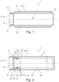
- FIG 1 a first embodiment of the sensor 1 according to the invention is shown.
- the cylindrically shaped housing 3 is closed off on the left-hand side by a membrane 21 forming the base 2 .
- Housing 3 and membrane 21 are made of stainless steel.
- the membrane 21 is adjoined to the right by the electromechanical converter 4 for sound generation.
- a shielding can 9 forms the end of the converter 4 towards the housing interior 22.
- an inner cylindrical tube section 10 of the housing 3 is surrounded by a likewise outer tube section 11, the fastening part 6, at a distance.
- the casing 3 is thus constituted by pipe sections which can be fitted into one another and which are arranged coaxially and form a peripheral slot in which the elastomeric part is injected.
- the space between the fastening part 6 and the functional part 7 to be isolated is filled by the injected elastomer part 8 .
- the sensor can be stretched for attachment to attachment part 6.
- the housing 3 of the sensor 1 is also of cylindrical design, but in this embodiment the housing has the same diameter 13 throughout.
- the fastening part 6 is tapered in diameter at its left open end 23 so that it extends into the functional part 7 in a region 24 and the wall section 15 overlaps the functional part 7 .
- the intermediate space formed forms a peripheral gap 12 which is filled by the ring-shaped transparent elastomer part 8 .
- This elastomeric part is made in the space by injecting a thermoplastic elastomeric mass using suitable tools.
- the elastomer part 8 then simultaneously connects the functional part and the fastening part as an adhesive bond.
- a form-fitting connection is also achieved because bores 25 are introduced in one or both parts 6 and 7, into which the thermoplastic elastomer mass penetrates during the injection molding process.
- the fastening part 6 is also divided at the joint 26, so that a ring section 19 is created which, together with the elastomer part 8, functional part 7 and converter 4, forms a subassembly 20 which can only be connected after the converter 4 has made contact with an electronic subassembly 16 is assembled with the remaining fastening part 6.
- the figure 2 schematically indicated circuit board of an electronic assembly 16 arranged.
- light-emitting diodes 18 are also provided as illuminants 17 on it.
- the switching state of the sensor can be signaled by the LEDs 18 . Since the elastomer part 8 is transparent, the light from the LED17 can penetrate outwards through the bore 25 and the elastomer part 8 and can be perceived there through this display window at the end of the fastening part.
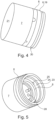
- the assembly 20 described above is in figure 3 shown in more detail as a section.
- the Figures 4 and 5 show perspective views from different directions.
- the sound transducer 4 was developed in particular for the food sector, in which the acoustically active surface consists of a membrane 21 made of stainless steel. The thickness of the membrane 21 is between 50 ⁇ m and 20 ⁇ m.
- the actual sound transducer 4 consists of a piezoelectric element 5 and an acoustic matching layer 27 which is glued to the inside of the stainless steel membrane.
- the membrane conducts the sound very well and acts as a sound bridge. Therefore, there is a particularly high risk of interference signals.
- the shielding can 9 which has an opening 28 through which lines (not shown) can be routed to the piezoelectric element 5.
- a retaining ring 29 which forms the bridge to the functional part 7 , is also inserted to hold the shielding cup 9 in the functional part 7 . Only the annular section 19 with the annular groove 30 is visible from the fastening part 6 , which serves as a weld point or rolled depression for fastening the remaining fastening part 6 .
- the fastening part thus serves to fasten the sensor, while the active housing part assumes the function of the sensor.
Landscapes
- Engineering & Computer Science (AREA)
- Physics & Mathematics (AREA)
- Acoustics & Sound (AREA)
- Multimedia (AREA)
- General Physics & Mathematics (AREA)
- Remote Sensing (AREA)
- Radar, Positioning & Navigation (AREA)
- Computer Networks & Wireless Communication (AREA)
- Transducers For Ultrasonic Waves (AREA)
- Investigating Or Analyzing Materials By The Use Of Ultrasonic Waves (AREA)
- Measurement Of Mechanical Vibrations Or Ultrasonic Waves (AREA)
- Ultra Sonic Daignosis Equipment (AREA)
- Geophysics And Detection Of Objects (AREA)
Claims (6)
- Capteur sonique ou ultrasonique (1) pour l'émission et/ou la réception de sons ou d'ultrasons avec un boîtier (3) en forme de pot fermé par un fond (2), un transducteur électromécanique (4), de préférence un élément piézoélectrique (5), pour générer et/ou enregistrer des sons ou ultrasons à travers le fond (2), le boîtier (3) étant divisé en une partie de fixation (6) pour fixer le capteur (1) et une partie fonctionnelle (7), la partie fonctionnelle (7) et la partie de fixation (6) étant assemblées au moyen d'une partie élastomère (8), caractérisé en ce que le transducteur électromécanique (4) est entouré par le fond (2) et par une coupelle de blindage (9) de préférence métallique, la partie fonctionnelle (7) et la partie de fixation (6) étant réalisées sous forme de sections de tube (10, 11) pouvant être insérée l'une dans l'autre qui sont disposées coaxialement et forment une fente périphérique (12), la partie élastomère (8) étant transparente et le capteur (1) présentant un module électronique (16) avec des moyens d'éclairage (17), de préférence au moins une diode électroluminescente (18), dont la lumière émise est visible à travers la partie élastomère (8).
- Capteur sonique ou ultrasonique selon la revendication 1, caractérisé en ce que la partie fonctionnelle (7) et la partie de fixation (6) sont disposées axialement l'une derrière l'autre et ont de préférence le même diamètre (13), la partie élastomère (8) étant disposée entre la partie fonctionnelle (7) et la partie de fixation (6).
- Capteur sonique ou ultrasonique selon la revendication 1 ou 2, caractérisé en ce que la coupelle de blindage (9) est conçue comme élément de la partie fonctionnelle (7) ou que la coupelle de blindage (9) est circonférenciellement entourée par la partie fonctionnelle (7).
- Capteur sonique ou ultrasonique selon la revendication 1 ou 2, caractérisé en ce que la partie fonctionnelle (7) présente une section annulaire (14) réalisée de façon chevauchante sous forme d'une section de paroi (15) de la partie de fixation (6).
- Capteur de son ou d'ultrasons selon la revendication 1 ou 2, caractérisé en ce que la partie élastomère (8) est reliée par complémentarité de forme avec la partie fonctionnelle (7) et/ou la partie de fixation (6).
- Capteur sonique ou ultrasonique selon la revendication 1 ou 2, caractérisé en ce que la partie de fixation (6) présente une section annulaire divisée (19) réalisée pour former un ensemble (20) avec la partie fonctionnelle (7) et la partie élastomère (8).
Applications Claiming Priority (2)
| Application Number | Priority Date | Filing Date | Title |
|---|---|---|---|
| DE202013104569U DE202013104569U1 (de) | 2013-10-09 | 2013-10-09 | Ultraschallsensor |
| PCT/EP2014/071613 WO2015052269A1 (fr) | 2013-10-09 | 2014-10-09 | Capteur à ultrasons |
Publications (2)
| Publication Number | Publication Date |
|---|---|
| EP3055858A1 EP3055858A1 (fr) | 2016-08-17 |
| EP3055858B1 true EP3055858B1 (fr) | 2023-04-05 |
Family
ID=49781858
Family Applications (1)
| Application Number | Title | Priority Date | Filing Date |
|---|---|---|---|
| EP14781572.4A Active EP3055858B1 (fr) | 2013-10-09 | 2014-10-09 | Capteur à ultrasons |
Country Status (4)
| Country | Link |
|---|---|
| EP (1) | EP3055858B1 (fr) |
| DE (1) | DE202013104569U1 (fr) |
| ES (1) | ES2948495T3 (fr) |
| WO (1) | WO2015052269A1 (fr) |
Families Citing this family (8)
| Publication number | Priority date | Publication date | Assignee | Title |
|---|---|---|---|---|
| CN104678377A (zh) * | 2013-11-27 | 2015-06-03 | 法雷奥汽车内部控制(深圳)有限公司 | 超声波传感器及其制造方法 |
| CN106525181B (zh) * | 2016-12-26 | 2023-04-18 | 上海宾峰仪器科技有限公司 | 双壳体带温补气体超声换能器 |
| DE102017107331A1 (de) | 2017-04-05 | 2018-10-11 | Turck Holding Gmbh | Ultraschallsensor |
| WO2020060694A1 (fr) | 2018-09-21 | 2020-03-26 | Ecolab Usa Inc. | Dispositif et procédé de surveillance de niveau de fluide portatifs |
| CN110000514B (zh) * | 2019-02-28 | 2024-06-28 | 信利光电股份有限公司 | 一种超声振动滚压加工装置 |
| CN111337105A (zh) * | 2020-04-01 | 2020-06-26 | 北京精波仪表有限公司 | 一种超声波物位计 |
| DE102020114777A1 (de) | 2020-06-03 | 2021-12-09 | Tdk Electronics Ag | Ultraschallwandler und Verfahren zum Betrieb eines Ultraschallwandlers |
| DE102024132291B3 (de) | 2024-11-06 | 2026-04-09 | Krohne Ag | Verfahren zum Betreiben eines Ultraschalldurchflussmessgeräts und Ultraschalldurchflussmessgerät |
Citations (1)
| Publication number | Priority date | Publication date | Assignee | Title |
|---|---|---|---|---|
| JP2002228742A (ja) * | 2001-01-31 | 2002-08-14 | Ngk Spark Plug Co Ltd | 超音波センサ |
Family Cites Families (6)
| Publication number | Priority date | Publication date | Assignee | Title |
|---|---|---|---|---|
| DE19927797C1 (de) * | 1999-06-18 | 2000-12-07 | Fraunhofer Ges Forschung | Ultraschallwandler und Verfahren zu seiner Herstellung |
| DE10216037A1 (de) | 2002-04-11 | 2003-10-23 | Endress & Hauser Gmbh & Co Kg | Schall-oder Ultraschallsensor |
| JP4438667B2 (ja) * | 2005-03-29 | 2010-03-24 | 株式会社デンソー | 超音波センサ及び超音波振動子 |
| CN101297591B (zh) * | 2005-12-14 | 2011-09-07 | 株式会社村田制作所 | 超声波换能器 |
| DE102006028213A1 (de) * | 2006-06-14 | 2007-12-20 | Valeo Schalter Und Sensoren Gmbh | Ultraschallsensor mit Entkopplungselement |
| DE202011109555U1 (de) * | 2011-12-23 | 2012-02-29 | Gaslock Gmbh | Vorrichtung zur Messung des Füllstands von Flüssigkeiten |
-
2013
- 2013-10-09 DE DE202013104569U patent/DE202013104569U1/de not_active Expired - Lifetime
-
2014
- 2014-10-09 ES ES14781572T patent/ES2948495T3/es active Active
- 2014-10-09 WO PCT/EP2014/071613 patent/WO2015052269A1/fr not_active Ceased
- 2014-10-09 EP EP14781572.4A patent/EP3055858B1/fr active Active
Patent Citations (1)
| Publication number | Priority date | Publication date | Assignee | Title |
|---|---|---|---|---|
| JP2002228742A (ja) * | 2001-01-31 | 2002-08-14 | Ngk Spark Plug Co Ltd | 超音波センサ |
Also Published As
| Publication number | Publication date |
|---|---|
| WO2015052269A1 (fr) | 2015-04-16 |
| DE202013104569U1 (de) | 2013-11-25 |
| EP3055858A1 (fr) | 2016-08-17 |
| ES2948495T3 (es) | 2023-09-13 |
Similar Documents
| Publication | Publication Date | Title |
|---|---|---|
| EP3055858B1 (fr) | Capteur à ultrasons | |
| EP2877870B1 (fr) | Dispositif capteur à ultrasons doté d'un anneau de découplage amélioré et véhicule automobile | |
| EP0644999B1 (fr) | Indicateur de niveau | |
| WO1991005226A1 (fr) | Indicateur de niveau forme de composants assemblables | |
| DE102008027974A1 (de) | Ultraschallsensor | |
| EP3183142B1 (fr) | Dispositif d'habillage pour un véhicule automobile, système, véhicule automobile et procédé de fabrication | |
| DE102008029772A1 (de) | Verfahren und Messsystem zur Bestimmung und/oder Überwachung des Durchflusses eines Messmediums durch ein Messrohr | |
| EP2743653A1 (fr) | Transducteur ultrasonore et procédé d'excitation et/ou de détection de signaux utrasoniques | |
| CH675476A5 (fr) | ||
| EP2639788B1 (fr) | Capteur ultrasonique | |
| EP3010651B1 (fr) | Dispositif de détection d'environnement comprenant un transducteur ultrasonore modulaire et véhicule automobile équipé d'un dispositif de détection d'environnement de ce type | |
| WO2001061375A1 (fr) | Detecteur a ultrasons | |
| EP3359975B1 (fr) | Capteur comprenant un ensemble ultrasonique monolithique | |
| DE102013211630A1 (de) | Elektroakustischer Wandler | |
| EP2850398A1 (fr) | Procédé de fabrication d'un corps de transducteur à ultrasons comprenant un élément transducteur piézoélectrique intégré | |
| EP1493302B1 (fr) | Capteur de sons ou ultrasons | |
| DE102018200315A1 (de) | Schallwandler | |
| EP2116474A1 (fr) | Capteur d'ultrasons | |
| EP3868481B1 (fr) | Capteur à ultrasons | |
| DE102013225872A1 (de) | Karosserieteil für ein Kraftfahrzeug | |
| WO2010139488A1 (fr) | Transducteur ultrasonore comportant un anneau de découplage, et procédé de montage | |
| DE102013211619A1 (de) | Umfeldsensiereinrichtung mit Ultraschallwandler, und Kraftfahrzeug mit einer derartigen Umfeldsensiereinrichtung | |
| DE20302582U1 (de) | Vorrichtung zur Feststellung einer Flüssigkeit | |
| DE102022005131B4 (de) | Ultraschall-Wandler | |
| DE102022005133A1 (de) | Ultraschall-Wandler |
Legal Events
| Date | Code | Title | Description |
|---|---|---|---|
| PUAI | Public reference made under article 153(3) epc to a published international application that has entered the european phase |
Free format text: ORIGINAL CODE: 0009012 |
|
| 17P | Request for examination filed |
Effective date: 20160224 |
|
| AK | Designated contracting states |
Kind code of ref document: A1 Designated state(s): AL AT BE BG CH CY CZ DE DK EE ES FI FR GB GR HR HU IE IS IT LI LT LU LV MC MK MT NL NO PL PT RO RS SE SI SK SM TR |
|
| AX | Request for extension of the european patent |
Extension state: BA ME |
|
| DAX | Request for extension of the european patent (deleted) | ||
| STAA | Information on the status of an ep patent application or granted ep patent |
Free format text: STATUS: EXAMINATION IS IN PROGRESS |
|
| 17Q | First examination report despatched |
Effective date: 20210401 |
|
| REG | Reference to a national code |
Ref country code: DE Ref legal event code: R079 Ref document number: 502014016524 Country of ref document: DE Free format text: PREVIOUS MAIN CLASS: G10K0011000000 Ipc: G01S0007521000 |
|
| GRAP | Despatch of communication of intention to grant a patent |
Free format text: ORIGINAL CODE: EPIDOSNIGR1 |
|
| STAA | Information on the status of an ep patent application or granted ep patent |
Free format text: STATUS: GRANT OF PATENT IS INTENDED |
|
| RIC1 | Information provided on ipc code assigned before grant |
Ipc: G10K 9/122 20060101ALN20221102BHEP Ipc: G01S 15/88 20060101ALN20221102BHEP Ipc: G01F 23/296 20060101ALN20221102BHEP Ipc: G10K 11/00 20060101ALI20221102BHEP Ipc: G10K 9/22 20060101ALI20221102BHEP Ipc: G01S 7/521 20060101AFI20221102BHEP |
|
| INTG | Intention to grant announced |
Effective date: 20221129 |
|
| RAP3 | Party data changed (applicant data changed or rights of an application transferred) |
Owner name: PEPPERL + FUCHS GMBH |
|
| RIC1 | Information provided on ipc code assigned before grant |
Ipc: G10K 9/122 20060101ALN20221121BHEP Ipc: G01S 15/88 20060101ALN20221121BHEP Ipc: G01F 23/296 20060101ALN20221121BHEP Ipc: G10K 11/00 20060101ALI20221121BHEP Ipc: G10K 9/22 20060101ALI20221121BHEP Ipc: G01S 7/521 20060101AFI20221121BHEP |
|
| GRAS | Grant fee paid |
Free format text: ORIGINAL CODE: EPIDOSNIGR3 |
|
| GRAA | (expected) grant |
Free format text: ORIGINAL CODE: 0009210 |
|
| STAA | Information on the status of an ep patent application or granted ep patent |
Free format text: STATUS: THE PATENT HAS BEEN GRANTED |
|
| AK | Designated contracting states |
Kind code of ref document: B1 Designated state(s): AL AT BE BG CH CY CZ DE DK EE ES FI FR GB GR HR HU IE IS IT LI LT LU LV MC MK MT NL NO PL PT RO RS SE SI SK SM TR |
|
| REG | Reference to a national code |
Ref country code: GB Ref legal event code: FG4D Free format text: NOT ENGLISH |
|
| REG | Reference to a national code |
Ref country code: DE Ref legal event code: R096 Ref document number: 502014016524 Country of ref document: DE |
|
| REG | Reference to a national code |
Ref country code: CH Ref legal event code: EP |
|
| REG | Reference to a national code |
Ref country code: AT Ref legal event code: REF Ref document number: 1558624 Country of ref document: AT Kind code of ref document: T Effective date: 20230415 |
|
| REG | Reference to a national code |
Ref country code: IE Ref legal event code: FG4D Free format text: LANGUAGE OF EP DOCUMENT: GERMAN |
|
| REG | Reference to a national code |
Ref country code: LT Ref legal event code: MG9D |
|
| REG | Reference to a national code |
Ref country code: NL Ref legal event code: MP Effective date: 20230405 |
|
| REG | Reference to a national code |
Ref country code: DE Ref legal event code: R081 Ref document number: 502014016524 Country of ref document: DE Owner name: PEPPERL+FUCHS SE, DE Free format text: FORMER OWNER: PEPPERL & FUCHS GMBH, 68307 MANNHEIM, DE Ref country code: ES Ref legal event code: FG2A Ref document number: 2948495 Country of ref document: ES Kind code of ref document: T3 Effective date: 20230913 |
|
| PG25 | Lapsed in a contracting state [announced via postgrant information from national office to epo] |
Ref country code: NL Free format text: LAPSE BECAUSE OF FAILURE TO SUBMIT A TRANSLATION OF THE DESCRIPTION OR TO PAY THE FEE WITHIN THE PRESCRIBED TIME-LIMIT Effective date: 20230405 |
|
| PG25 | Lapsed in a contracting state [announced via postgrant information from national office to epo] |
Ref country code: SE Free format text: LAPSE BECAUSE OF FAILURE TO SUBMIT A TRANSLATION OF THE DESCRIPTION OR TO PAY THE FEE WITHIN THE PRESCRIBED TIME-LIMIT Effective date: 20230405 Ref country code: PT Free format text: LAPSE BECAUSE OF FAILURE TO SUBMIT A TRANSLATION OF THE DESCRIPTION OR TO PAY THE FEE WITHIN THE PRESCRIBED TIME-LIMIT Effective date: 20230807 Ref country code: NO Free format text: LAPSE BECAUSE OF FAILURE TO SUBMIT A TRANSLATION OF THE DESCRIPTION OR TO PAY THE FEE WITHIN THE PRESCRIBED TIME-LIMIT Effective date: 20230705 |
|
| PG25 | Lapsed in a contracting state [announced via postgrant information from national office to epo] |
Ref country code: RS Free format text: LAPSE BECAUSE OF FAILURE TO SUBMIT A TRANSLATION OF THE DESCRIPTION OR TO PAY THE FEE WITHIN THE PRESCRIBED TIME-LIMIT Effective date: 20230405 Ref country code: PL Free format text: LAPSE BECAUSE OF FAILURE TO SUBMIT A TRANSLATION OF THE DESCRIPTION OR TO PAY THE FEE WITHIN THE PRESCRIBED TIME-LIMIT Effective date: 20230405 Ref country code: LV Free format text: LAPSE BECAUSE OF FAILURE TO SUBMIT A TRANSLATION OF THE DESCRIPTION OR TO PAY THE FEE WITHIN THE PRESCRIBED TIME-LIMIT Effective date: 20230405 Ref country code: LT Free format text: LAPSE BECAUSE OF FAILURE TO SUBMIT A TRANSLATION OF THE DESCRIPTION OR TO PAY THE FEE WITHIN THE PRESCRIBED TIME-LIMIT Effective date: 20230405 Ref country code: IS Free format text: LAPSE BECAUSE OF FAILURE TO SUBMIT A TRANSLATION OF THE DESCRIPTION OR TO PAY THE FEE WITHIN THE PRESCRIBED TIME-LIMIT Effective date: 20230805 Ref country code: HR Free format text: LAPSE BECAUSE OF FAILURE TO SUBMIT A TRANSLATION OF THE DESCRIPTION OR TO PAY THE FEE WITHIN THE PRESCRIBED TIME-LIMIT Effective date: 20230405 Ref country code: GR Free format text: LAPSE BECAUSE OF FAILURE TO SUBMIT A TRANSLATION OF THE DESCRIPTION OR TO PAY THE FEE WITHIN THE PRESCRIBED TIME-LIMIT Effective date: 20230706 Ref country code: AL Free format text: LAPSE BECAUSE OF FAILURE TO SUBMIT A TRANSLATION OF THE DESCRIPTION OR TO PAY THE FEE WITHIN THE PRESCRIBED TIME-LIMIT Effective date: 20230405 |
|
| REG | Reference to a national code |
Ref country code: AT Ref legal event code: PC Ref document number: 1558624 Country of ref document: AT Kind code of ref document: T Owner name: PEPPERL + FUCHS SE, DE Effective date: 20231024 |
|
| PG25 | Lapsed in a contracting state [announced via postgrant information from national office to epo] |
Ref country code: FI Free format text: LAPSE BECAUSE OF FAILURE TO SUBMIT A TRANSLATION OF THE DESCRIPTION OR TO PAY THE FEE WITHIN THE PRESCRIBED TIME-LIMIT Effective date: 20230405 |
|
| REG | Reference to a national code |
Ref country code: DE Ref legal event code: R097 Ref document number: 502014016524 Country of ref document: DE |
|
| PG25 | Lapsed in a contracting state [announced via postgrant information from national office to epo] |
Ref country code: SK Free format text: LAPSE BECAUSE OF FAILURE TO SUBMIT A TRANSLATION OF THE DESCRIPTION OR TO PAY THE FEE WITHIN THE PRESCRIBED TIME-LIMIT Effective date: 20230405 |
|
| PG25 | Lapsed in a contracting state [announced via postgrant information from national office to epo] |
Ref country code: SM Free format text: LAPSE BECAUSE OF FAILURE TO SUBMIT A TRANSLATION OF THE DESCRIPTION OR TO PAY THE FEE WITHIN THE PRESCRIBED TIME-LIMIT Effective date: 20230405 Ref country code: SK Free format text: LAPSE BECAUSE OF FAILURE TO SUBMIT A TRANSLATION OF THE DESCRIPTION OR TO PAY THE FEE WITHIN THE PRESCRIBED TIME-LIMIT Effective date: 20230405 Ref country code: RO Free format text: LAPSE BECAUSE OF FAILURE TO SUBMIT A TRANSLATION OF THE DESCRIPTION OR TO PAY THE FEE WITHIN THE PRESCRIBED TIME-LIMIT Effective date: 20230405 Ref country code: EE Free format text: LAPSE BECAUSE OF FAILURE TO SUBMIT A TRANSLATION OF THE DESCRIPTION OR TO PAY THE FEE WITHIN THE PRESCRIBED TIME-LIMIT Effective date: 20230405 Ref country code: DK Free format text: LAPSE BECAUSE OF FAILURE TO SUBMIT A TRANSLATION OF THE DESCRIPTION OR TO PAY THE FEE WITHIN THE PRESCRIBED TIME-LIMIT Effective date: 20230405 Ref country code: CZ Free format text: LAPSE BECAUSE OF FAILURE TO SUBMIT A TRANSLATION OF THE DESCRIPTION OR TO PAY THE FEE WITHIN THE PRESCRIBED TIME-LIMIT Effective date: 20230405 |
|
| PLBE | No opposition filed within time limit |
Free format text: ORIGINAL CODE: 0009261 |
|
| STAA | Information on the status of an ep patent application or granted ep patent |
Free format text: STATUS: NO OPPOSITION FILED WITHIN TIME LIMIT |
|
| 26N | No opposition filed |
Effective date: 20240108 |
|
| PG25 | Lapsed in a contracting state [announced via postgrant information from national office to epo] |
Ref country code: SI Free format text: LAPSE BECAUSE OF FAILURE TO SUBMIT A TRANSLATION OF THE DESCRIPTION OR TO PAY THE FEE WITHIN THE PRESCRIBED TIME-LIMIT Effective date: 20230405 |
|
| REG | Reference to a national code |
Ref country code: ES Ref legal event code: PC2A Owner name: PEPPERL + FUCHS SE Effective date: 20240507 |
|
| PG25 | Lapsed in a contracting state [announced via postgrant information from national office to epo] |
Ref country code: SI Free format text: LAPSE BECAUSE OF FAILURE TO SUBMIT A TRANSLATION OF THE DESCRIPTION OR TO PAY THE FEE WITHIN THE PRESCRIBED TIME-LIMIT Effective date: 20230405 Ref country code: MC Free format text: LAPSE BECAUSE OF FAILURE TO SUBMIT A TRANSLATION OF THE DESCRIPTION OR TO PAY THE FEE WITHIN THE PRESCRIBED TIME-LIMIT Effective date: 20230405 |
|
| REG | Reference to a national code |
Ref country code: BE Ref legal event code: MM Effective date: 20231031 |
|
| PG25 | Lapsed in a contracting state [announced via postgrant information from national office to epo] |
Ref country code: LU Free format text: LAPSE BECAUSE OF NON-PAYMENT OF DUE FEES Effective date: 20231009 |
|
| GBPC | Gb: european patent ceased through non-payment of renewal fee |
Effective date: 20231009 |
|
| PG25 | Lapsed in a contracting state [announced via postgrant information from national office to epo] |
Ref country code: LU Free format text: LAPSE BECAUSE OF NON-PAYMENT OF DUE FEES Effective date: 20231009 |
|
| PG25 | Lapsed in a contracting state [announced via postgrant information from national office to epo] |
Ref country code: GB Free format text: LAPSE BECAUSE OF NON-PAYMENT OF DUE FEES Effective date: 20231009 |
|
| PG25 | Lapsed in a contracting state [announced via postgrant information from national office to epo] |
Ref country code: GB Free format text: LAPSE BECAUSE OF NON-PAYMENT OF DUE FEES Effective date: 20231009 |
|
| PG25 | Lapsed in a contracting state [announced via postgrant information from national office to epo] |
Ref country code: BE Free format text: LAPSE BECAUSE OF NON-PAYMENT OF DUE FEES Effective date: 20231031 |
|
| PG25 | Lapsed in a contracting state [announced via postgrant information from national office to epo] |
Ref country code: IE Free format text: LAPSE BECAUSE OF NON-PAYMENT OF DUE FEES Effective date: 20231009 |
|
| PG25 | Lapsed in a contracting state [announced via postgrant information from national office to epo] |
Ref country code: IE Free format text: LAPSE BECAUSE OF NON-PAYMENT OF DUE FEES Effective date: 20231009 |
|
| PG25 | Lapsed in a contracting state [announced via postgrant information from national office to epo] |
Ref country code: BG Free format text: LAPSE BECAUSE OF FAILURE TO SUBMIT A TRANSLATION OF THE DESCRIPTION OR TO PAY THE FEE WITHIN THE PRESCRIBED TIME-LIMIT Effective date: 20230405 |
|
| PG25 | Lapsed in a contracting state [announced via postgrant information from national office to epo] |
Ref country code: BG Free format text: LAPSE BECAUSE OF FAILURE TO SUBMIT A TRANSLATION OF THE DESCRIPTION OR TO PAY THE FEE WITHIN THE PRESCRIBED TIME-LIMIT Effective date: 20230405 |
|
| PG25 | Lapsed in a contracting state [announced via postgrant information from national office to epo] |
Ref country code: CY Free format text: LAPSE BECAUSE OF FAILURE TO SUBMIT A TRANSLATION OF THE DESCRIPTION OR TO PAY THE FEE WITHIN THE PRESCRIBED TIME-LIMIT; INVALID AB INITIO Effective date: 20141009 |
|
| PG25 | Lapsed in a contracting state [announced via postgrant information from national office to epo] |
Ref country code: HU Free format text: LAPSE BECAUSE OF FAILURE TO SUBMIT A TRANSLATION OF THE DESCRIPTION OR TO PAY THE FEE WITHIN THE PRESCRIBED TIME-LIMIT; INVALID AB INITIO Effective date: 20141009 |
|
| REG | Reference to a national code |
Ref country code: CH Ref legal event code: U11 Free format text: ST27 STATUS EVENT CODE: U-0-0-U10-U11 (AS PROVIDED BY THE NATIONAL OFFICE) Effective date: 20251101 |
|
| PG25 | Lapsed in a contracting state [announced via postgrant information from national office to epo] |
Ref country code: TR Free format text: LAPSE BECAUSE OF FAILURE TO SUBMIT A TRANSLATION OF THE DESCRIPTION OR TO PAY THE FEE WITHIN THE PRESCRIBED TIME-LIMIT Effective date: 20230405 |
|
| PGFP | Annual fee paid to national office [announced via postgrant information from national office to epo] |
Ref country code: DE Payment date: 20251020 Year of fee payment: 12 |
|
| PGFP | Annual fee paid to national office [announced via postgrant information from national office to epo] |
Ref country code: AT Payment date: 20251021 Year of fee payment: 12 |
|
| PGFP | Annual fee paid to national office [announced via postgrant information from national office to epo] |
Ref country code: IT Payment date: 20251031 Year of fee payment: 12 |
|
| PGFP | Annual fee paid to national office [announced via postgrant information from national office to epo] |
Ref country code: FR Payment date: 20251022 Year of fee payment: 12 |
|
| PGFP | Annual fee paid to national office [announced via postgrant information from national office to epo] |
Ref country code: CH Payment date: 20251101 Year of fee payment: 12 |
|
| PGFP | Annual fee paid to national office [announced via postgrant information from national office to epo] |
Ref country code: ES Payment date: 20251114 Year of fee payment: 12 |