EP3183142B1 - Dispositif d'habillage pour un véhicule automobile, système, véhicule automobile et procédé de fabrication - Google Patents
Dispositif d'habillage pour un véhicule automobile, système, véhicule automobile et procédé de fabrication Download PDFInfo
- Publication number
- EP3183142B1 EP3183142B1 EP15750996.9A EP15750996A EP3183142B1 EP 3183142 B1 EP3183142 B1 EP 3183142B1 EP 15750996 A EP15750996 A EP 15750996A EP 3183142 B1 EP3183142 B1 EP 3183142B1
- Authority
- EP
- European Patent Office
- Prior art keywords
- movement elements
- trim
- damping
- ultrasonic sensor
- trim part
- Prior art date
- Legal status (The legal status is an assumption and is not a legal conclusion. Google has not performed a legal analysis and makes no representation as to the accuracy of the status listed.)
- Active
Links
Images
Classifications
-
- B—PERFORMING OPERATIONS; TRANSPORTING
- B60—VEHICLES IN GENERAL
- B60R—VEHICLES, VEHICLE FITTINGS, OR VEHICLE PARTS, NOT OTHERWISE PROVIDED FOR
- B60R19/00—Wheel guards; Radiator guards, e.g. grilles; Obstruction removers; Fittings damping bouncing force in collisions
- B60R19/02—Bumpers, i.e. impact receiving or absorbing members for protecting vehicles or fending off blows from other vehicles or objects
- B60R19/48—Bumpers, i.e. impact receiving or absorbing members for protecting vehicles or fending off blows from other vehicles or objects combined with, or convertible into, other devices or objects, e.g. bumpers combined with road brushes, bumpers convertible into beds
- B60R19/483—Bumpers, i.e. impact receiving or absorbing members for protecting vehicles or fending off blows from other vehicles or objects combined with, or convertible into, other devices or objects, e.g. bumpers combined with road brushes, bumpers convertible into beds with obstacle sensors of electric or electronic type
-
- G—PHYSICS
- G01—MEASURING; TESTING
- G01S—RADIO DIRECTION-FINDING; RADIO NAVIGATION; DETERMINING DISTANCE OR VELOCITY BY USE OF RADIO WAVES; LOCATING OR PRESENCE-DETECTING BY USE OF THE REFLECTION OR RERADIATION OF RADIO WAVES; ANALOGOUS ARRANGEMENTS USING OTHER WAVES
- G01S15/00—Systems using the reflection or reradiation of acoustic waves, e.g. sonar systems
- G01S15/88—Sonar systems specially adapted for specific applications
- G01S15/93—Sonar systems specially adapted for specific applications for anti-collision purposes
- G01S15/931—Sonar systems specially adapted for specific applications for anti-collision purposes of land vehicles
-
- G—PHYSICS
- G01—MEASURING; TESTING
- G01S—RADIO DIRECTION-FINDING; RADIO NAVIGATION; DETERMINING DISTANCE OR VELOCITY BY USE OF RADIO WAVES; LOCATING OR PRESENCE-DETECTING BY USE OF THE REFLECTION OR RERADIATION OF RADIO WAVES; ANALOGOUS ARRANGEMENTS USING OTHER WAVES
- G01S7/00—Details of systems according to groups G01S13/00, G01S15/00, G01S17/00
- G01S7/52—Details of systems according to groups G01S13/00, G01S15/00, G01S17/00 of systems according to group G01S15/00
- G01S7/521—Constructional features
-
- G—PHYSICS
- G10—MUSICAL INSTRUMENTS; ACOUSTICS
- G10K—SOUND-PRODUCING DEVICES; METHODS OR DEVICES FOR PROTECTING AGAINST, OR FOR DAMPING, NOISE OR OTHER ACOUSTIC WAVES IN GENERAL; ACOUSTICS NOT OTHERWISE PROVIDED FOR
- G10K11/00—Methods or devices for transmitting, conducting or directing sound in general; Methods or devices for protecting against, or for damping, noise or other acoustic waves in general
- G10K11/002—Devices for damping, suppressing, obstructing or conducting sound in acoustic devices
-
- G—PHYSICS
- G10—MUSICAL INSTRUMENTS; ACOUSTICS
- G10K—SOUND-PRODUCING DEVICES; METHODS OR DEVICES FOR PROTECTING AGAINST, OR FOR DAMPING, NOISE OR OTHER ACOUSTIC WAVES IN GENERAL; ACOUSTICS NOT OTHERWISE PROVIDED FOR
- G10K9/00—Devices in which sound is produced by vibrating a diaphragm or analogous element, e.g. fog horns, vehicle hooters or buzzers
- G10K9/18—Details, e.g. bulbs, pumps, pistons, switches or casings
- G10K9/22—Mountings; Casings
-
- G—PHYSICS
- G01—MEASURING; TESTING
- G01S—RADIO DIRECTION-FINDING; RADIO NAVIGATION; DETERMINING DISTANCE OR VELOCITY BY USE OF RADIO WAVES; LOCATING OR PRESENCE-DETECTING BY USE OF THE REFLECTION OR RERADIATION OF RADIO WAVES; ANALOGOUS ARRANGEMENTS USING OTHER WAVES
- G01S15/00—Systems using the reflection or reradiation of acoustic waves, e.g. sonar systems
- G01S15/88—Sonar systems specially adapted for specific applications
- G01S15/93—Sonar systems specially adapted for specific applications for anti-collision purposes
- G01S15/931—Sonar systems specially adapted for specific applications for anti-collision purposes of land vehicles
- G01S2015/937—Sonar systems specially adapted for specific applications for anti-collision purposes of land vehicles sensor installation details
- G01S2015/938—Sonar systems specially adapted for specific applications for anti-collision purposes of land vehicles sensor installation details in the bumper area
Definitions
- the present invention relates to a cladding device for a motor vehicle, having a cladding part, which has a receiving region for arranging an ultrasonic sensor, and having a damping device for damping an oscillation generated as a result of an ultrasonic signal emitted by the ultrasonic sensor, wherein the damper surrounds the receiving region at least in regions.
- the invention also relates to an arrangement of such a covering device with an ultrasonic sensor.
- the present invention relates to a motor vehicle with at least one such arrangement.
- the present invention relates to a method for producing a cladding device for a motor vehicle.
- Ultrasonic sensors are installed in a known manner in the front area and in the rear area of the motor vehicle, in particular on bumpers. They are associated with driver assistance systems and provide information about the environment of the motor vehicle, namely the distances between the motor vehicle on the one hand and the obstacles located in its surroundings on the other hand.
- driver assistance systems may be, for example, parking assistance systems, blind spot monitoring systems, distance keeping systems, brake assist systems or the like.
- ultrasonic sensors are installed in bumpers uncovered and thus visible. This means that they are arranged in continuous recesses in the bumper and are visible on the outside. A pot-shaped membrane of the ultrasonic sensor extends through the continuous recess of the bumper, so that the front side of the membrane, via which ultrasonic waves are emitted and received, terminates flush with the outer surface of the bumper.
- These ultrasonic sensors have the distinct disadvantage that they are visibly arranged and thus affect the entire optical image of the motor vehicle.
- the present interest is directed to hidden or hidden built-ultrasonic sensors, which are not visible from the outside covered by the bumper when looking at the bumper.
- the ultrasonic sensor is located on a rear side of the bumper, so that the front side of the diaphragm - possibly via an additional mounting cover - is brought into contact with the rear side of the bumper.
- the ultrasonic signals are transmitted and received through the material of the bumper.
- an area of the bumper vibrates together with the diaphragm of the ultrasonic sensor. It is thus often necessary that this oscillating region of the bumper is limited by means of a damping device formed of ceramic.
- a damping device formed of ceramic, which has a passage opening through which the cup-shaped membrane of the ultrasonic sensor extends, so that the stiffening element is arranged around the membrane and also - possibly via a mounting lid - with the back of the bumper is brought into plant.
- a damping element is for example in the DE 10 2011 105 017 A1 described.
- the ultrasonic sensor must be mechanically fixed behind the bumper. This is necessary so that the ultrasonic sensor can transmit lossless through the bumper.
- the transmitting surface of the ultrasonic sensor - as the front surface of the membrane - mechanically fixed to the bumper are connected or formed with a lossless coupling element or mounting lid between the front of the membrane and the bumper.
- the abovementioned damping device with a large modulus of elasticity is required tightly around the transducer or around the diaphragm.
- Such a stiffening ring must be mechanically firmly connected to the bumper.
- the Ultrasonic sensor device has a stiffening element with a through opening through which the membrane extends.
- the stiffening element is porous and connected by its porous front cohesively with a mounting lid.
- the porous front has corresponding teeth or small recesses.
- the mounting lid is formed of a plastic material, which is molded onto the damping element.
- the damping element may comprise at least one recess
- the mounting cover may comprise at least one pin which engages in the associated recess of the damping element, wherein the at least one pin is formed by the injection molding of the plastic material.
- the US 20080089177 A1 discloses a cladding device for a motor vehicle according to the Oberberggrip of claim 1. It is an object of the present invention to provide a method, as the vibrations of an ultrasonic sensor, which is hidden behind a cowling of a motor vehicle, can be attenuated easier and cheaper. This object is achieved by a cladding device, by an arrangement, by a motor vehicle and by a method having the features according to the respective independent claims. Advantageous developments of the present invention are the subject of the dependent claims.
- a cladding device according to the invention for a motor vehicle comprises a cladding part, which has a receiving area for arranging an ultrasound sensor.
- the covering device comprises a damping device for damping a vibration generated as a result of an ultrasonic signal emitted by the ultrasonic sensor, wherein the damping device surrounds the receiving region at least in regions.
- the damping device has movement elements which are connected to the covering part, wherein a respective shape and / or a mechanical property of the movement elements is designed such that at least a part of the movement elements can be excited by the oscillation to move.
- the covering device comprises a covering part, which may be formed, for example, as a bumper or as a fender.
- the damping device comprises a plurality of movement elements, which are firmly connected to the covering part.
- the movement elements may be formed, for example, substantially cylindrical or conical.
- the movement elements may preferably each be designed in the manner of a villus.
- a respective shape and / or a mechanical property of the movement elements are designed such that at least a part of the movement elements is excited by the vibration to a movement.
- the geometric configuration and / or the mechanical properties of the respective movement elements can be designed such that the movement elements are excited to mechanical vibrations as a result of the vibration of the trim part.
- the resonance frequency of the movement elements can be designed such that they oscillate in resonance frequency as a result of the mechanical vibrations of the trim part. It can also be provided that the movement elements have different resonance frequencies.
- the vibration energy of the trim part is converted into a kinetic energy of the moving elements. In this way, the vibration of the trim panel can be attenuated us / or localized.
- the movement elements serve to dampen a mechanical vibration of the trim part.
- the movement elements can also serve to dampen structure-borne noise that propagates within the trim part.
- the movement elements of the damping device can serve to limit the range of vibration of the trim part, which is excited to vibrate by the ultrasonic signal.
- the damping device can limit the area of the trim part that vibrates together with a membrane of the ultrasonic sensor.
- the damping device can also serve to limit the area of the trim part in which ultrasonic waves are coupled in by the ultrasonic sensor.
- the damper may be used instead of a damper made of ceramic or comprising a ceramic ring.
- a cost-effective Damping device for damping vibrations of a trim part are provided.
- the movement elements are preferably connected to the covering part such that the movement elements extend substantially perpendicular to a surface of the covering part.
- the respective main extension direction of the movement elements extends substantially perpendicular to a main extension direction of the trim part. Movement elements, which are arranged substantially perpendicular to the cladding element, can be made simple and space saving.
- the movement elements are integrally connected to the covering part. In this way, a reliable connection between the moving elements and the cowling can be provided. Thus, it can be guaranteed that the movement elements remain reliably connected to the trim part during operation of the motor vehicle. Furthermore, such a material connection between the movement elements and the trim part can be provided easily and inexpensively.
- the movement elements are preferably connected to the trim part by an adhesive method and / or by friction welding.
- the moving elements may also be formed of a plastic.
- the moving elements can be friction welded to the cowling.
- the movement elements are injection-molded, for example, to the trim part. If the trim part is formed of a metal and the moving elements are also formed of a metal, the moving elements can be connected to the trim part, for example by means of a welding process or a soldering process. It can also be provided that the movement elements are connected by means of an adhesive method with the trim part.
- the movement elements are formed integrally with the trim part.
- the Paneling device be made by means of an injection molding process.
- both the movement elements and the trim part are made of metal, a corresponding die-casting method can be used.
- the movement elements can be integrated already in the production of the trim part.
- the movement elements are arranged unevenly distributed to each other. By the uneven distribution of the movement elements on the surface of the cladding element can be prevented, for example, that the movement elements are excited by the vibration of the trim part to the mechanical vibration. It is also conceivable that the individual movement elements have different shapes or dimensions. It can also be provided that the movement elements are made of different materials.
- the movement elements have different resonance frequencies. This can be achieved, for example, that the vibration of the trim part is also attenuated, if the vibration is not assigned to a single frequency, but a frequency range.
- the movement elements can also be arranged relative to one another in such a way that at least some of the movement elements touch each other during their movement. Thus, friction is generated between the moving elements which damps the vibration due to the ultrasonic signal.
- the movement elements are each formed from a plastic and / or a ceramic and / or a metal.
- all movement elements may be made of plastic or of a ceramic or of a metal.
- a part of the movement elements made of a plastic and / or a part of the movement elements made of a metal and / or a part of the movement elements are made of a ceramic.
- the different movement elements have different mechanical properties or vibration properties that react differently to the vibration of the trim part.
- the mechanical vibration of the trim part can be reliably damped or limited.
- the damping device has a cover element which is connected to the movement elements on a side of the movement elements opposite the covering part.
- a cover element which the Movement elements are arranged.
- Such a cover element, on which the movement elements are arranged may for example be made of plastic and manufactured by means of an injection molding process.
- a cover element, on which the movement elements are arranged be made of metal and manufactured by means of a die-casting process.
- the cover element, on which the movement elements are arranged is thus designed in the manner of a brush.
- a brush-shaped element can be connected, for example, a material fit with the trim part.
- an adhesive method can be used.
- the moving elements can be easily arranged on the cladding element.
- the damping device comprises a first annular element having a first diameter and a second annular element having a second diameter, which is larger in comparison to the first diameter, which are arranged concentrically to one another on the covering part, wherein the movement elements in a space between the first and the second annular element are arranged.
- the two annular elements, which are arranged concentrically to one another, can be molded onto the surface of the trim part, for example. Furthermore, it is also conceivable that the annular elements are integrated in the manufacturing process of the trim part.
- the receiving area for the ultrasonic sensor is arranged within the first annular element.
- the ultrasonic sensor is surrounded by the damping element.
- the damping device has a damping material for damping a movement of the movement elements, wherein the damping material is arranged at least partially between the movement elements.
- the damping material may surround the moving elements.
- the area between the two annular elements can be filled with the damping material.
- the movement elements are surrounded only to a predetermined height of the damping material.
- the damping material preferably comprises an elastomer, in particular a silicone foam.
- a silicone foam can be formed, for example, by arranging corresponding air bubbles within a silicone.
- the silicone may for example be provided in a liquid phase and distributed between the movement elements. There it can be cured accordingly.
- a damping material for damping the movement of the moving elements can be provided in a simple and cost-effective manner.
- An arrangement according to the invention for a motor vehicle comprises a cladding device according to the invention and the ultrasound sensor which is designed to emit and / or receive an ultrasound signal, the ultrasound sensor being connected to the cladding device in a materially bonded manner.
- the ultrasonic sensor is preferably arranged in the receiving region of the covering device.
- the ultrasonic sensor can be adhesively bonded to the trim part with a corresponding adhesive.
- the arrangement preferably comprises a housing in which the ultrasonic sensor and a decoupling element for decoupling the ultrasonic sensor from the housing are arranged.
- the housing may be formed, for example, as a corresponding mounting cover.
- the housing may be made of plastic, for example.
- a decoupling element is further provided, which serves, for example, to mechanically decouple the ultrasonic sensor from the housing.
- the decoupling element may be formed, for example, of ceramic or an elastomer.
- a motor vehicle according to the invention comprises at least one arrangement according to the invention.
- the motor vehicle is designed in particular as a passenger car.
- the arrangement may for example be associated with a driver assistance system of the motor vehicle.
- a driver assistance system can be, for example, a parking assistance system, a blind spot monitoring system, a distance keeping system, a brake assist system or the like.
- An inventive method is used to produce a covering device for a motor vehicle.
- a covering part which has a receiving region for arranging an ultrasonic sensor, is provided.
- a damping device for damping an oscillation generated as a result of an ultrasonic signal emitted by the ultrasonic sensor is provided, wherein the Damper surrounds the receiving area at least partially.
- the damping device has movement elements that are connected to the covering part, wherein a respective shape and / or a mechanical property of the movement elements is designed such that at least a part of the movement elements can be excited by the vibration to a movement.
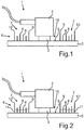
- Fig. 1 shows an arrangement of one for a motor vehicle in a sectional side view.
- the arrangement 1 comprises an ultrasonic sensor 2.
- the ultrasonic sensor 2 serves to transmit an ultrasonic signal and / or to receive an ultrasonic signal.
- the ultrasonic sensor 2 comprises a membrane 3, which is cup-shaped and is preferably made of aluminum.
- the ultrasonic sensor 2 comprises an actuator, not shown here, which in particular comprises a piezoelectric element.
- the actuator serves to set the membrane 3 in mechanical vibrations.
- mechanical vibrations of the membrane 3 can be detected with the piezoelectric element.
- the arrangement 1 comprises a cladding device 4.
- the cladding device 4 in turn comprises a cladding part 5.
- the cladding part 5 may be formed for example by a bodywork component of a motor vehicle.
- the cowling 5 may be a bumper of a motor vehicle.
- the trim part 5 is a fender or part of a door of the motor vehicle.
- the trim part 5 may be formed of a plastic or of a metal.
- the ultrasonic sensor 2 is arranged on a rear side 6 of the covering part 5 in a receiving region 16 of the covering device 4.
- the back 6 of the trim part 5 is the part of the trim part 5 of the motor vehicle, which is not visible from the outside.
- the ultrasonic sensor 2 is connected with its front side, ie in the emitting direction of the ultrasonic signal, with the rear side 6 of the trim part 5.
- the ultrasonic sensor 2 is firmly bonded to the trim part 5, for example by means of an adhesive.
- ultrasonic signals are emitted by the ultrasonic sensor 2. These are passed through the cowling 5 through. In this case, the cowling 5 is excited to mechanical vibrations. It may also be the case that structure-borne noise propagates within the trim part 5.
- the trim device 4 has a damping device 7.
- the damping device 7 has a plurality of moving elements 8.
- the movement elements 8 may be formed in the manner of villi.
- the movement elements 8 are arranged on the back 6 of the trim part. In this case, the movement elements 8 are arranged such that the main extension direction of the movement elements 8 extends substantially perpendicular to the main extension direction of the trim part 5.
- the damping element 7 has a first annular element 9, which has a first diameter, and a second annular element 10, which has a second diameter, which is larger in comparison to the first diameter, on.
- the two annular elements 9 and 10 are arranged concentrically with each other. In the space between the first annular member 9 and the second annular member 10, the moving elements 8 are arranged.
- the movement elements 8 may be made of plastic, metal and / or ceramic, for example.
- the shape and / or the mechanical properties of the movement elements 8 can be chosen so that it is excited by the vibration of the trim part 5, which is due to the ultrasonic signal, which is emitted and / or received by the ultrasonic sensor 2 is caused to mechanical vibrations ,
- the moving elements 8 can be excited to vibrate at their resonant frequency.
- the vibration energy of the trim part 5 can be converted into the kinetic energy of the moving elements 8.
- the vibration of the trim part 5 can be damped and / or limited locally within the damping device 7.
- the movement elements 8 can have different resonance frequencies.
- the movement elements 8 may have different lengths.
- the movement elements 8 are arranged unevenly within the damping device 7. Thus, for example, a vibration of the cladding element 5 can be reliably damped.
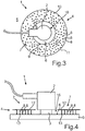
- Fig. 2 shows the arrangement according to Fig. 1 in a further embodiment.
- a damping material 11 is disposed between the moving elements 8.
- the damping material 11 is disposed in the space between the first annular member 9 and the second annular member 10.
- the damping material 11 may be formed, for example, by an elastomer, in particular a silicone foam.
- the damping material 11 extends only up to a predetermined height of the moving elements 8.
- the damping material 8 serves to damp a movement or a mechanical vibration of the moving elements eighth
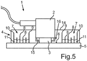
- Fig. 3 shows the arrangement 1 according to Fig. 2 in a top view. It can be seen in particular that the movement elements 8 are arranged distributed unevenly to each other within the damping device 7.
- Fig. 4 shows an arrangement 1 according to the invention.
- the damping device 4 comprises a cover element 12.
- the cover element 12 may be materially connected to the movement elements 8. It can also be provided that the cover element 12 is integrally formed with the movement elements 8.
- the cover element 12 and the movement elements 8 form a brush-shaped arrangement.
- the movement elements 8 are firmly bonded to the covering part 5, for example by means of an adhesive 13.
- Fig. 5 shows the arrangement according to Fig. 2 in a further embodiment.
- the arrangement 1 also comprises a housing 14.
- the housing 14 may be made of a plastic, for example.
- a decoupling element 15 is provided within the housing 14.
- the decoupling element 15 surrounds the diaphragm 3 concentrically in the present embodiment.
- the decoupling element 15 may be made of ceramic or a plastic, for example.
- the decoupling element 15 serves to decouple the ultrasonic sensor 2 or the membrane 3 mechanically from the housing 14.
Landscapes
- Engineering & Computer Science (AREA)
- Physics & Mathematics (AREA)
- Radar, Positioning & Navigation (AREA)
- Remote Sensing (AREA)
- Acoustics & Sound (AREA)
- Multimedia (AREA)
- Computer Networks & Wireless Communication (AREA)
- General Physics & Mathematics (AREA)
- Mechanical Engineering (AREA)
- General Electrical Machinery Utilizing Piezoelectricity, Electrostriction Or Magnetostriction (AREA)
- Measurement Of Velocity Or Position Using Acoustic Or Ultrasonic Waves (AREA)
Claims (14)
- Dispositif d'habillage (4) pour un véhicule automobile, comprenant une partie d'habillage (5) qui présente une région de logement (16) pour recevoir un capteur à ultrasons (2), et un dispositif d'amortissement (7) pour l'amortissement d'une oscillation produite suite à un signal à ultrasons émis par le capteur à ultrasons (2), le dispositif d'amortissement (7) entourant au moins en partie la région de réception (16), le dispositif d'amortissement (7) présentant des éléments mobiles (8) qui sont connectés à la partie d'habillage (5), une forme respective et/ou une propriété mécanique respective des éléments mobiles (8) étant conçues de telle sorte qu'au moins une partie des éléments mobiles (8) puissent être incités à se déplacer sous l'effet de l'oscillation, caractérisé en ce que le dispositif d'amortissement (7) présente un élément de couvercle (12) qui est connecté aux éléments mobiles (8) sur un côté des éléments mobiles (8) opposé à la partie d'habillage (5).
- Dispositif d'habillage (4) selon la revendication 1,
caractérisé en ce que
les éléments mobiles (8) sont connectés à la partie d'habillage (5) de telle sorte que les éléments mobiles (8) s'étendent essentiellement perpendiculairement à une surface de la partie d'habillage (5). - Dispositif d'habillage (4) selon la revendication 1 ou 2,
caractérisé en ce que
les éléments mobiles (8) sont connectés par engagement par liaison de matière à la partie d'habillage (5). - Dispositif d'habillage (4) selon la revendication 3,
caractérisé en ce que
les éléments mobiles (8) sont connectés par un procédé de collage et/ou par soudage par friction à la partie d'habillage (5). - Dispositif d'habillage (4) selon la revendication 1 ou 2,
caractérisé en ce que
les éléments mobiles (8) sont réalisés d'une seule pièce avec la partie d'habillage (5). - Dispositif d'habillage (4) selon l'une quelconque des revendications précédentes,
caractérisé en ce que
les éléments mobiles (8) sont disposés de manière répartie irrégulièrement les uns par rapport aux autres. - Dispositif d'habillage (4) selon l'une quelconque des revendications précédentes,
caractérisé en ce que
les éléments mobile (8) sont à chaque fois formés d'un plastique et/ou d'une céramique et/ou d'un métal. - Dispositif d'habillage (4) selon l'une quelconque des revendications précédentes,
caractérisé en ce que
le dispositif d'amortissement (7) présente un premier élément annulaire (9) avec un premier diamètre et un deuxième élément annulaire (10) avec un deuxième diamètre plus grand que le premier diamètre, qui sont disposés concentriquement l'un par rapport à l'autre sur la partie d'habillage (5), les éléments mobiles (8) étant disposés dans un espace intermédiaire entre le premier et le deuxième élément annulaire (9, 10) . - Dispositif d'habillage (4) selon l'une quelconque des revendications précédentes,
caractérisé en ce que
le dispositif d'amortissement (7) présente un matériau d'amortissement (11) pour l'amortissement d'un mouvement des éléments mobiles (8), le matériau d'amortissement (11) étant disposés au moins en partie entre les éléments mobiles (8). - Dispositif d'habillage (4) selon la revendication 9,
caractérisé en ce que
le matériau d'amortissement (11) comprend un élastomère, en particulier une mousse de silicone. - Agencement (1) pour un véhicule automobile, comprenant un dispositif d'habillage (4) selon l'une quelconque des revendications précédentes, et le capteur à ultrasons (2) qui est conçu pour émettre et/ou recevoir un signal à ultrasons, le capteur à ultrasons (2) étant connecté par liaison de matière au dispositif d'habillage (4).
- Agencement (1) selon la revendication 11,
caractérisé en ce que
l'agencement comprend un boîtier (14) dans lequel est disposé le capteur à ultrasons (2) et un élément de désaccouplement (15) pour désaccoupler le capteur à ultrasons (2) du boîtier (14). - Véhicule automobile comprenant au moins un agencement (1) selon la revendication 12.
- Procédé de fabrication d'un dispositif d'habillage (4) pour un véhicule automobile, dans lequel est prévue une partie d'habillage (5) qui présente une région de réception (16) pour disposer un capteur à ultrasons (2), et un dispositif d'amortissement (7) pour l'amortissement d'une oscillation générée suite à un signal à ultrasons émis par le capteur à ultrasons (2), le dispositif d'amortissement (7) entourant la région de réception (16) au moins en partie, le dispositif d'amortissement (7) présentant des éléments mobiles (8) qui sont connectés à la partie d'habillage (5), une forme respective et/ou une propriété mécanique respective des éléments mobiles (8) étant conçues de telle sorte qu'au moins une partie des éléments mobiles (8) puissent être incités à se déplacer sous l'effet de l'oscillation, caractérisé en ce que le dispositif d'amortissement (7) présente un élément de couvercle (12) qui est connecté aux éléments mobiles (8) sur un côté des éléments mobiles (8) opposé à la partie d'habillage (5).
Applications Claiming Priority (2)
| Application Number | Priority Date | Filing Date | Title |
|---|---|---|---|
| DE102014111947.9A DE102014111947A1 (de) | 2014-08-21 | 2014-08-21 | Verkleidungsvorrichtung für ein Kraftfahrzeug, Anordnung, Kraftfahrzeug sowie Herstellungsverfahren |
| PCT/EP2015/068657 WO2016026766A1 (fr) | 2014-08-21 | 2015-08-13 | Dispositif d'habillage pour un véhicule automobile, système, véhicule automobile et procédé de fabrication |
Publications (2)
| Publication Number | Publication Date |
|---|---|
| EP3183142A1 EP3183142A1 (fr) | 2017-06-28 |
| EP3183142B1 true EP3183142B1 (fr) | 2018-09-26 |
Family
ID=53879502
Family Applications (1)
| Application Number | Title | Priority Date | Filing Date |
|---|---|---|---|
| EP15750996.9A Active EP3183142B1 (fr) | 2014-08-21 | 2015-08-13 | Dispositif d'habillage pour un véhicule automobile, système, véhicule automobile et procédé de fabrication |
Country Status (3)
| Country | Link |
|---|---|
| EP (1) | EP3183142B1 (fr) |
| DE (1) | DE102014111947A1 (fr) |
| WO (1) | WO2016026766A1 (fr) |
Families Citing this family (7)
| Publication number | Priority date | Publication date | Assignee | Title |
|---|---|---|---|---|
| DE102015116442A1 (de) | 2015-09-29 | 2017-03-30 | Valeo Schalter Und Sensoren Gmbh | Dämpfungseinrichtung für ein Außenteil, Anordnung mit einer Dämpfungseinrichtung sowie Kraftfahrzeug |
| DE102016202307A1 (de) * | 2016-02-16 | 2017-08-17 | Robert Bosch Gmbh | Halterung für einen Sensor |
| DE102017127587A1 (de) * | 2017-11-22 | 2019-05-23 | Valeo Schalter Und Sensoren Gmbh | Anordnung für ein Kraftfahrzeug mit einem Ultraschallsensor und mit einem Dämpfungselement, welches Armierungselemente aufweist sowie Vorrichtung |
| DE102018100594A1 (de) | 2018-01-12 | 2019-07-18 | Valeo Schalter Und Sensoren Gmbh | Ultraschallsensoranordnung für ein Kraftfahrzeug mit Elementen zur Reduzierung einer Ausbreitung von Biegewellen sowie dazugehöriges Herstellungsverfahren |
| DE102018105267B3 (de) | 2018-03-07 | 2019-04-25 | Valeo Schalter Und Sensoren Gmbh | Dämpfungselement für einen Ultraschallsensor |
| JP2024010549A (ja) * | 2022-07-12 | 2024-01-24 | 株式会社Soken | 物体検出装置 |
| DE102023110886A1 (de) * | 2023-04-27 | 2024-10-31 | Valeo Schalter Und Sensoren Gmbh | Verfahren zum verdeckten montieren eines ultraschallsensors an einem karosseriebauteil |
Family Cites Families (4)
| Publication number | Priority date | Publication date | Assignee | Title |
|---|---|---|---|---|
| JP2007114182A (ja) * | 2005-09-22 | 2007-05-10 | Denso Corp | 超音波センサの取付け構造 |
| JP4917401B2 (ja) * | 2006-10-05 | 2012-04-18 | 株式会社日本自動車部品総合研究所 | 障害物検出装置 |
| DE102011105017A1 (de) | 2011-06-20 | 2012-12-20 | Valeo Schalter Und Sensoren Gmbh | Ultraschallsensorvorrichtung für ein Fahrzeug sowie Anordnung mit einer derartigen Ultraschallsensorvorrichtung |
| DE102012106694A1 (de) | 2012-07-24 | 2014-02-13 | Valeo Schalter Und Sensoren Gmbh | Ultraschallsensorvorrichtung mit einem Versteifungselement und einem Montagedeckel, Anordnung und Verfahren zum Herstellen einer solchen Ultraschallsensorvorrichtung |
-
2014
- 2014-08-21 DE DE102014111947.9A patent/DE102014111947A1/de not_active Withdrawn
-
2015
- 2015-08-13 EP EP15750996.9A patent/EP3183142B1/fr active Active
- 2015-08-13 WO PCT/EP2015/068657 patent/WO2016026766A1/fr not_active Ceased
Also Published As
| Publication number | Publication date |
|---|---|
| DE102014111947A1 (de) | 2016-02-25 |
| WO2016026766A1 (fr) | 2016-02-25 |
| EP3183142A1 (fr) | 2017-06-28 |
Similar Documents
| Publication | Publication Date | Title |
|---|---|---|
| EP3183142B1 (fr) | Dispositif d'habillage pour un véhicule automobile, système, véhicule automobile et procédé de fabrication | |
| EP2559024B1 (fr) | Procédé pour commander un capteur ultrasonore et capteur ultrasonore | |
| EP2877873B1 (fr) | Ensemble capteur à ultrasons comportant un capteur à ultrasons dans la calandre, véhicule à moteur et procédé correspondant | |
| EP2877870B1 (fr) | Dispositif capteur à ultrasons doté d'un anneau de découplage amélioré et véhicule automobile | |
| DE102006055168A1 (de) | Hinderniserfassungsvorrichtung | |
| EP2660627B1 (fr) | Ensemble de détection comprenant un composant de véhicule plat et un capteur à ultrasons | |
| DE102012208059A1 (de) | Trägerelement mit integrierter Sensoreinheit | |
| EP2877990B1 (fr) | Dispositif capteur d'ultrasons | |
| EP3055858B1 (fr) | Capteur à ultrasons | |
| DE102017108341B4 (de) | Ultraschallsensorvorrichtung für ein Kraftfahrzeug mit einer Sendeeinrichtung und separaten Empfangseinrichtungen, Fahrerassistenzsystem sowie Kraftfahrzeug | |
| EP2909831A2 (fr) | Dispositif capteur à ultrasons comportant un élément raidisseur, ensemble, véhicule à moteur et procédé de fabrication d'un ensemble | |
| EP3010651B1 (fr) | Dispositif de détection d'environnement comprenant un transducteur ultrasonore modulaire et véhicule automobile équipé d'un dispositif de détection d'environnement de ce type | |
| EP3012655B1 (fr) | Dispositif de capteur à ultrasons pour un véhicule automobile, système, véhicule automobile | |
| DE102009040374A1 (de) | Ultraschallwandler mit einem Entkopplungsring | |
| EP3012654A1 (fr) | Capteur a ultrasons pour un vehicule automobile, systeme, vehicule automobile et procede de fabrication | |
| DE102018100121B4 (de) | Ultraschallsensor für ein Kraftfahrzeug mit einer aus zwei Materialien gefertigten Membran, Ultraschallsensorvorrichtung, Fahrerassistenzsystem sowie Herstellungsverfahren | |
| EP3688748A1 (fr) | Transducteur acoustique | |
| EP3130514A1 (fr) | Systeme de carenage pour un vehicule automobile comprenant une partie de carenage dotee d'ouvertures de passage, vehicule automobile et procede | |
| DE102016107865B4 (de) | Ultraschallsensor für ein Kraftfahrzeug, Fahrerassistenzsystem, Kraftfahrzeug sowie Verfahren zum Herstellen eines Ultraschallsensors | |
| DE102015106240A1 (de) | Ultraschallsensor für ein Kraftfahrzeug mit einer Durchgangsöffnungen aufweisenden Membran, Verkleidungsanordnung sowie Kraftfahrzeug | |
| DE102022005131B4 (de) | Ultraschall-Wandler | |
| DE102022005133B4 (de) | Ultraschall-Wandler | |
| DE102022130025B3 (de) | Ultraschall-Wandler | |
| WO2017108494A1 (fr) | Dispositif de détection par ultrasons muni d'une carte de circuit imprimé flexible au moins par endroits, système de détection par ultrasons et véhicule automobile | |
| DE102024205631A1 (de) | Signalübertragende Struktur für eine Ultraschallwandler-Anordnung und Ultraschallwandler-Anordnung |
Legal Events
| Date | Code | Title | Description |
|---|---|---|---|
| STAA | Information on the status of an ep patent application or granted ep patent |
Free format text: STATUS: THE INTERNATIONAL PUBLICATION HAS BEEN MADE |
|
| PUAI | Public reference made under article 153(3) epc to a published international application that has entered the european phase |
Free format text: ORIGINAL CODE: 0009012 |
|
| STAA | Information on the status of an ep patent application or granted ep patent |
Free format text: STATUS: REQUEST FOR EXAMINATION WAS MADE |
|
| 17P | Request for examination filed |
Effective date: 20170221 |
|
| AK | Designated contracting states |
Kind code of ref document: A1 Designated state(s): AL AT BE BG CH CY CZ DE DK EE ES FI FR GB GR HR HU IE IS IT LI LT LU LV MC MK MT NL NO PL PT RO RS SE SI SK SM TR |
|
| AX | Request for extension of the european patent |
Extension state: BA ME |
|
| DAV | Request for validation of the european patent (deleted) | ||
| DAX | Request for extension of the european patent (deleted) | ||
| GRAP | Despatch of communication of intention to grant a patent |
Free format text: ORIGINAL CODE: EPIDOSNIGR1 |
|
| STAA | Information on the status of an ep patent application or granted ep patent |
Free format text: STATUS: GRANT OF PATENT IS INTENDED |
|
| INTG | Intention to grant announced |
Effective date: 20180503 |
|
| GRAS | Grant fee paid |
Free format text: ORIGINAL CODE: EPIDOSNIGR3 |
|
| GRAA | (expected) grant |
Free format text: ORIGINAL CODE: 0009210 |
|
| STAA | Information on the status of an ep patent application or granted ep patent |
Free format text: STATUS: THE PATENT HAS BEEN GRANTED |
|
| AK | Designated contracting states |
Kind code of ref document: B1 Designated state(s): AL AT BE BG CH CY CZ DE DK EE ES FI FR GB GR HR HU IE IS IT LI LT LU LV MC MK MT NL NO PL PT RO RS SE SI SK SM TR |
|
| REG | Reference to a national code |
Ref country code: GB Ref legal event code: FG4D Free format text: NOT ENGLISH |
|
| REG | Reference to a national code |
Ref country code: CH Ref legal event code: EP |
|
| REG | Reference to a national code |
Ref country code: AT Ref legal event code: REF Ref document number: 1045610 Country of ref document: AT Kind code of ref document: T Effective date: 20181015 |
|
| REG | Reference to a national code |
Ref country code: IE Ref legal event code: FG4D Free format text: LANGUAGE OF EP DOCUMENT: GERMAN |
|
| REG | Reference to a national code |
Ref country code: DE Ref legal event code: R096 Ref document number: 502015006122 Country of ref document: DE |
|
| REG | Reference to a national code |
Ref country code: SE Ref legal event code: TRGR |
|
| REG | Reference to a national code |
Ref country code: NL Ref legal event code: MP Effective date: 20180926 |
|
| PG25 | Lapsed in a contracting state [announced via postgrant information from national office to epo] |
Ref country code: BG Free format text: LAPSE BECAUSE OF FAILURE TO SUBMIT A TRANSLATION OF THE DESCRIPTION OR TO PAY THE FEE WITHIN THE PRESCRIBED TIME-LIMIT Effective date: 20181226 Ref country code: NO Free format text: LAPSE BECAUSE OF FAILURE TO SUBMIT A TRANSLATION OF THE DESCRIPTION OR TO PAY THE FEE WITHIN THE PRESCRIBED TIME-LIMIT Effective date: 20181226 Ref country code: LT Free format text: LAPSE BECAUSE OF FAILURE TO SUBMIT A TRANSLATION OF THE DESCRIPTION OR TO PAY THE FEE WITHIN THE PRESCRIBED TIME-LIMIT Effective date: 20180926 Ref country code: RS Free format text: LAPSE BECAUSE OF FAILURE TO SUBMIT A TRANSLATION OF THE DESCRIPTION OR TO PAY THE FEE WITHIN THE PRESCRIBED TIME-LIMIT Effective date: 20180926 Ref country code: GR Free format text: LAPSE BECAUSE OF FAILURE TO SUBMIT A TRANSLATION OF THE DESCRIPTION OR TO PAY THE FEE WITHIN THE PRESCRIBED TIME-LIMIT Effective date: 20181227 Ref country code: FI Free format text: LAPSE BECAUSE OF FAILURE TO SUBMIT A TRANSLATION OF THE DESCRIPTION OR TO PAY THE FEE WITHIN THE PRESCRIBED TIME-LIMIT Effective date: 20180926 |
|
| REG | Reference to a national code |
Ref country code: LT Ref legal event code: MG4D |
|
| PG25 | Lapsed in a contracting state [announced via postgrant information from national office to epo] |
Ref country code: LV Free format text: LAPSE BECAUSE OF FAILURE TO SUBMIT A TRANSLATION OF THE DESCRIPTION OR TO PAY THE FEE WITHIN THE PRESCRIBED TIME-LIMIT Effective date: 20180926 Ref country code: AL Free format text: LAPSE BECAUSE OF FAILURE TO SUBMIT A TRANSLATION OF THE DESCRIPTION OR TO PAY THE FEE WITHIN THE PRESCRIBED TIME-LIMIT Effective date: 20180926 Ref country code: HR Free format text: LAPSE BECAUSE OF FAILURE TO SUBMIT A TRANSLATION OF THE DESCRIPTION OR TO PAY THE FEE WITHIN THE PRESCRIBED TIME-LIMIT Effective date: 20180926 |
|
| PG25 | Lapsed in a contracting state [announced via postgrant information from national office to epo] |
Ref country code: IT Free format text: LAPSE BECAUSE OF FAILURE TO SUBMIT A TRANSLATION OF THE DESCRIPTION OR TO PAY THE FEE WITHIN THE PRESCRIBED TIME-LIMIT Effective date: 20180926 Ref country code: EE Free format text: LAPSE BECAUSE OF FAILURE TO SUBMIT A TRANSLATION OF THE DESCRIPTION OR TO PAY THE FEE WITHIN THE PRESCRIBED TIME-LIMIT Effective date: 20180926 Ref country code: PL Free format text: LAPSE BECAUSE OF FAILURE TO SUBMIT A TRANSLATION OF THE DESCRIPTION OR TO PAY THE FEE WITHIN THE PRESCRIBED TIME-LIMIT Effective date: 20180926 Ref country code: CZ Free format text: LAPSE BECAUSE OF FAILURE TO SUBMIT A TRANSLATION OF THE DESCRIPTION OR TO PAY THE FEE WITHIN THE PRESCRIBED TIME-LIMIT Effective date: 20180926 Ref country code: NL Free format text: LAPSE BECAUSE OF FAILURE TO SUBMIT A TRANSLATION OF THE DESCRIPTION OR TO PAY THE FEE WITHIN THE PRESCRIBED TIME-LIMIT Effective date: 20180926 Ref country code: RO Free format text: LAPSE BECAUSE OF FAILURE TO SUBMIT A TRANSLATION OF THE DESCRIPTION OR TO PAY THE FEE WITHIN THE PRESCRIBED TIME-LIMIT Effective date: 20180926 Ref country code: ES Free format text: LAPSE BECAUSE OF FAILURE TO SUBMIT A TRANSLATION OF THE DESCRIPTION OR TO PAY THE FEE WITHIN THE PRESCRIBED TIME-LIMIT Effective date: 20180926 Ref country code: IS Free format text: LAPSE BECAUSE OF FAILURE TO SUBMIT A TRANSLATION OF THE DESCRIPTION OR TO PAY THE FEE WITHIN THE PRESCRIBED TIME-LIMIT Effective date: 20190126 |
|
| PG25 | Lapsed in a contracting state [announced via postgrant information from national office to epo] |
Ref country code: PT Free format text: LAPSE BECAUSE OF FAILURE TO SUBMIT A TRANSLATION OF THE DESCRIPTION OR TO PAY THE FEE WITHIN THE PRESCRIBED TIME-LIMIT Effective date: 20190126 Ref country code: SK Free format text: LAPSE BECAUSE OF FAILURE TO SUBMIT A TRANSLATION OF THE DESCRIPTION OR TO PAY THE FEE WITHIN THE PRESCRIBED TIME-LIMIT Effective date: 20180926 Ref country code: SM Free format text: LAPSE BECAUSE OF FAILURE TO SUBMIT A TRANSLATION OF THE DESCRIPTION OR TO PAY THE FEE WITHIN THE PRESCRIBED TIME-LIMIT Effective date: 20180926 |
|
| REG | Reference to a national code |
Ref country code: DE Ref legal event code: R097 Ref document number: 502015006122 Country of ref document: DE |
|
| PG25 | Lapsed in a contracting state [announced via postgrant information from national office to epo] |
Ref country code: DK Free format text: LAPSE BECAUSE OF FAILURE TO SUBMIT A TRANSLATION OF THE DESCRIPTION OR TO PAY THE FEE WITHIN THE PRESCRIBED TIME-LIMIT Effective date: 20180926 |
|
| PLBE | No opposition filed within time limit |
Free format text: ORIGINAL CODE: 0009261 |
|
| STAA | Information on the status of an ep patent application or granted ep patent |
Free format text: STATUS: NO OPPOSITION FILED WITHIN TIME LIMIT |
|
| 26N | No opposition filed |
Effective date: 20190627 |
|
| PG25 | Lapsed in a contracting state [announced via postgrant information from national office to epo] |
Ref country code: SI Free format text: LAPSE BECAUSE OF FAILURE TO SUBMIT A TRANSLATION OF THE DESCRIPTION OR TO PAY THE FEE WITHIN THE PRESCRIBED TIME-LIMIT Effective date: 20180926 |
|
| PG25 | Lapsed in a contracting state [announced via postgrant information from national office to epo] |
Ref country code: TR Free format text: LAPSE BECAUSE OF FAILURE TO SUBMIT A TRANSLATION OF THE DESCRIPTION OR TO PAY THE FEE WITHIN THE PRESCRIBED TIME-LIMIT Effective date: 20180926 |
|
| REG | Reference to a national code |
Ref country code: DE Ref legal event code: R081 Ref document number: 502015006122 Country of ref document: DE Owner name: VOLKSWAGEN AKTIENGESELLSCHAFT, DE Free format text: FORMER OWNER: VALEO SCHALTER UND SENSOREN GMBH, 74321 BIETIGHEIM-BISSINGEN, DE Ref country code: DE Ref legal event code: R081 Ref document number: 502015006122 Country of ref document: DE Owner name: VALEO SCHALTER UND SENSOREN GMBH, DE Free format text: FORMER OWNER: VALEO SCHALTER UND SENSOREN GMBH, 74321 BIETIGHEIM-BISSINGEN, DE |
|
| PG25 | Lapsed in a contracting state [announced via postgrant information from national office to epo] |
Ref country code: LU Free format text: LAPSE BECAUSE OF NON-PAYMENT OF DUE FEES Effective date: 20190813 Ref country code: MC Free format text: LAPSE BECAUSE OF FAILURE TO SUBMIT A TRANSLATION OF THE DESCRIPTION OR TO PAY THE FEE WITHIN THE PRESCRIBED TIME-LIMIT Effective date: 20180926 Ref country code: LI Free format text: LAPSE BECAUSE OF NON-PAYMENT OF DUE FEES Effective date: 20190831 Ref country code: CH Free format text: LAPSE BECAUSE OF NON-PAYMENT OF DUE FEES Effective date: 20190831 |
|
| REG | Reference to a national code |
Ref country code: BE Ref legal event code: MM Effective date: 20190831 |
|
| PG25 | Lapsed in a contracting state [announced via postgrant information from national office to epo] |
Ref country code: IE Free format text: LAPSE BECAUSE OF NON-PAYMENT OF DUE FEES Effective date: 20190813 |
|
| PG25 | Lapsed in a contracting state [announced via postgrant information from national office to epo] |
Ref country code: BE Free format text: LAPSE BECAUSE OF NON-PAYMENT OF DUE FEES Effective date: 20190831 |
|
| PG25 | Lapsed in a contracting state [announced via postgrant information from national office to epo] |
Ref country code: CY Free format text: LAPSE BECAUSE OF FAILURE TO SUBMIT A TRANSLATION OF THE DESCRIPTION OR TO PAY THE FEE WITHIN THE PRESCRIBED TIME-LIMIT Effective date: 20180926 |
|
| PG25 | Lapsed in a contracting state [announced via postgrant information from national office to epo] |
Ref country code: HU Free format text: LAPSE BECAUSE OF FAILURE TO SUBMIT A TRANSLATION OF THE DESCRIPTION OR TO PAY THE FEE WITHIN THE PRESCRIBED TIME-LIMIT; INVALID AB INITIO Effective date: 20150813 Ref country code: MT Free format text: LAPSE BECAUSE OF FAILURE TO SUBMIT A TRANSLATION OF THE DESCRIPTION OR TO PAY THE FEE WITHIN THE PRESCRIBED TIME-LIMIT Effective date: 20180926 |
|
| REG | Reference to a national code |
Ref country code: AT Ref legal event code: MM01 Ref document number: 1045610 Country of ref document: AT Kind code of ref document: T Effective date: 20200813 |
|
| PG25 | Lapsed in a contracting state [announced via postgrant information from national office to epo] |
Ref country code: AT Free format text: LAPSE BECAUSE OF NON-PAYMENT OF DUE FEES Effective date: 20200813 |
|
| PG25 | Lapsed in a contracting state [announced via postgrant information from national office to epo] |
Ref country code: MK Free format text: LAPSE BECAUSE OF FAILURE TO SUBMIT A TRANSLATION OF THE DESCRIPTION OR TO PAY THE FEE WITHIN THE PRESCRIBED TIME-LIMIT Effective date: 20180926 |
|
| PGFP | Annual fee paid to national office [announced via postgrant information from national office to epo] |
Ref country code: DE Payment date: 20250825 Year of fee payment: 11 |
|
| PGFP | Annual fee paid to national office [announced via postgrant information from national office to epo] |
Ref country code: GB Payment date: 20250826 Year of fee payment: 11 |
|
| PGFP | Annual fee paid to national office [announced via postgrant information from national office to epo] |
Ref country code: FR Payment date: 20250828 Year of fee payment: 11 |
|
| PGFP | Annual fee paid to national office [announced via postgrant information from national office to epo] |
Ref country code: SE Payment date: 20250826 Year of fee payment: 11 |