EP3056248B1 - Sicherungs- und abseilgerät über ein seil mit übersetzung und anti-panik-blockade - Google Patents
Sicherungs- und abseilgerät über ein seil mit übersetzung und anti-panik-blockade Download PDFInfo
- Publication number
- EP3056248B1 EP3056248B1 EP15200227.5A EP15200227A EP3056248B1 EP 3056248 B1 EP3056248 B1 EP 3056248B1 EP 15200227 A EP15200227 A EP 15200227A EP 3056248 B1 EP3056248 B1 EP 3056248B1
- Authority
- EP
- European Patent Office
- Prior art keywords
- lever
- cam
- rope
- belay
- descender device
- Prior art date
- Legal status (The legal status is an assumption and is not a legal conclusion. Google has not performed a legal analysis and makes no representation as to the accuracy of the status listed.)
- Active
Links
Images






Classifications
-
- A—HUMAN NECESSITIES
- A62—LIFE-SAVING; FIRE-FIGHTING
- A62B—DEVICES, APPARATUS OR METHODS FOR LIFE-SAVING
- A62B1/00—Devices for lowering persons from buildings or the like
- A62B1/06—Devices for lowering persons from buildings or the like by making use of rope-lowering devices
- A62B1/08—Devices for lowering persons from buildings or the like by making use of rope-lowering devices with brake mechanisms for the winches or pulleys
- A62B1/10—Devices for lowering persons from buildings or the like by making use of rope-lowering devices with brake mechanisms for the winches or pulleys mechanically operated
-
- A—HUMAN NECESSITIES
- A62—LIFE-SAVING; FIRE-FIGHTING
- A62B—DEVICES, APPARATUS OR METHODS FOR LIFE-SAVING
- A62B1/00—Devices for lowering persons from buildings or the like
- A62B1/06—Devices for lowering persons from buildings or the like by making use of rope-lowering devices
- A62B1/14—Devices for lowering persons from buildings or the like by making use of rope-lowering devices with brakes sliding on the rope
-
- A—HUMAN NECESSITIES
- A63—SPORTS; GAMES; AMUSEMENTS
- A63B—APPARATUS FOR PHYSICAL TRAINING, GYMNASTICS, SWIMMING, CLIMBING, OR FENCING; BALL GAMES; TRAINING EQUIPMENT
- A63B29/00—Apparatus for mountaineering
- A63B29/02—Mountain guy-ropes or accessories, e.g. avalanche ropes; Means for indicating the location of accidentally buried, e.g. snow-buried, persons
Definitions
- the figure 1 represents a self-locking rope insurance device described in detail in the document EP 2301631 . It comprises a cam-shaped pulley 10 arranged to cause a locking of the rope when the rope is under tension, and a control lever 11 cooperating with the cam 10 to cause a progressive release of the rope following a manual action on the lever 11 in the direction of the arrow F.
- the lever 11 acts on the cam 10 respectively with a multiplied effect in an initial part of its release stroke, and with a direct drive effect in a final part of its stroke.
- the relative displacement of the cam 10 relative to the displacement of the lever 11 is lower in the initial part of the race than in the final part, which allows a precise adjustment of the braking force and the speed of movement of the rope in the initial portion of the stroke of the lever 11.
- the cam 10 is articulated on an axis 12 of a flange 13 fixed, and the lever 11 control is articulated by an axis 14 on the cam 10.
- the lever 11 comprises a bearing pin 15 intended to come into contact against a stop 16 of the flange 13, said stop being located between the hinge pins 12, 14 of the respective cam 10 and lever 11 when the latter is turned in the direction of release. From this position, if the user pulls on the lever 11 in the unlocking clockwise direction, the cam 10 is urged clockwise with a reduced effort. By spending little energy, the user can exert a major effort on the cam 10 to overcome the effort required to unlock the rope, and then finely adjust the position of the cam 10 to modulate the tightening of the rope and thus settle finely the speed of scrolling of the
- the figure 1 represents the chute in a release position, obtained when the user continues to pull the lever 11 clockwise.
- the lug 15 disengages from the abutment 16 and bears against a wall of the cam 10.
- the lever 11 is found in a configuration without reduction of the drive, causing a direct and rapid displacement of the cam 14 to the position end of release stroke.
- the cam 10 no longer blocks the rope as long as the lever 11 is held in this position by the user.
- the lug 15 of the lever 11 remains in abutment on the cam 10 by establishing a permanent mechanical connection between the cam 10 and the lever 11. If the user is panicked during an uncontrolled descent along the rope, it may cling to the lever 11 by pulling strongly down. The rope is free, and the user can not stop at the expense of his safety.
- the antipanic function is known per se on conventional self-braking descenders as illustrated in the documents EP 2777772 and EP 2018894 , but not on a descending insurer with gear ratio for unlocking the cam.
- the object of the invention is to provide a rope descender insurer device, which can be easily unlocked manually to improve the fluidity of the descent along the rope, and benefiting from an automatic reblocking function in case of panic. 'user.
- control lever comprises transmission means cooperating with a guide ramp of the flange to interrupt the mechanical connection with the cam after passing an intermediate position of the lever, causing the exhausting said ramp out of the reduction zone, and that the end of the flange guide ramp corresponds to the anti-panic position of the transmission means, allowing automatic locking of the cam as soon as the reduction zone is exceeded .
- the transmission means comprise a drive rod articulated to the lever, and slidable along the guide ramp in said reduction zone for unlocking the cam.
- the transmission means are provided with a drive shaft integral with the lever, and cooperating with a pawl pivotally mounted on an axis of the flange, said pawl being pushed by the drive shaft against the guide ramp during the reduction zone to initiate the drive of the cam in the unlocking direction.
- the axis is configured to escape the clique in the intermediate anti-panic position.
- an over-travel of the lever in the unlocking direction beyond the intermediate position restores the mechanical connection with the cam, and drives it directly without reduction.
- the anti-panic function is manually reset by moving the control lever in the opposite direction to replace the transmission means in their original position on the side of the guide rail.
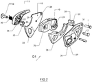
- the flange 13 is provided with a recess 23 allowing the passage of the rod 20 when it moves along the ramp 21 of guiding after actuation of the lever 11 in the unlocking direction.
- the recess 23 is delimited at its upper part by the guide ramp 21.
- the cam 10 has a first orifice 24 for the passage of the axis 12 fixed in a hole 26 of the flange 13, and a second orifice 25 for mounting of the axis 14 of articulation of the control lever 11.
- a second flange 27 is arranged opposite the first flange 13, and cooperates with a spacer 28 to hold the rope in place.
- the second flange 27 can be fixed or tilting.
- the cam 10 presses the rope against a braking surface 29, which is provided on a stud 30 inserted and fixed by a screw 31 between the two flanges 13, 27.
- the two flanges 13, 27 are provided holes 33, 34 for hooking a carabiner attachment (not shown).
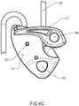
- the figure 3 shows the descender on the side of the cam 10, after the installation of a rope 32.
- the cam 10 is eccentrically mounted on the axis 12, and is shaped into a pulley around which is wound a loop of the rope 32.
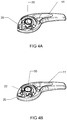
- FIGS. 4A and 4B represent the control lever 11 equipped with the drive rod 20, which can pivot about its axis 22.
- the latter is threaded into a blind hole of the lever 11, in the vicinity of the circular hole 35 for the passage of the axis 14 of the lever 11.
- a torsion spring 36 ( figure 2 ) is threaded coaxially on the axis 14 inside the orifice 35 to bias the cam 10 to the unlocking position.
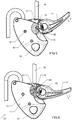
- the user unfolds the lever 11 by rotating it clockwise.
- the link 20 bears on the ramp 21 which defines the reduction zone for driving the cam 10 in the unlocking direction with a reduced effort.
- the rotation of the lever 11 causes the cam 10 to rotate in a predetermined ratio, for example 1/3.
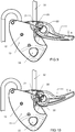
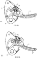
- FIGs 9 to 12 represent the various phases of manual reset to reactivate the antipanic function after the escape of the rod 20. It is sufficient to turn the lever 11 counterclockwise indicated by the arrow R ( figure 9 ), causing pivoting of the link 20 about its axis 22 when it bears on the flange 13 ( figure 10 ). On the figure 11 , the link 20 retracts by crossing the nose 38 of the flange 13, and returns to move into the original position inside the ramp 21 of the flange 13 by means of a spiral spring (see figure 12 ).
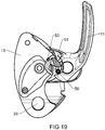
- FIGS 13 to 19 show a second embodiment of an insurer descender D2 according to the invention. Most of the parts are identical with the same reference numbers, only the means of implementation of the anti-panic function are different from those of the aforementioned device D1.
- the link 20 of the device D1 Figures 2-12 is replaced by a drive shaft 50 integral with the lever 11, said axis being intended to cooperate with a pawl 51 pivotally mounted on an axis 52 of the flange 13.
- the pawl 51 is preferably made of stainless steel, allowing contact with the axis 50 with high endurance.
- the shaft 50 pushes the pawl 51 bearing against the ramp 21 of the flange 13 to initiate the drive of the cam 10 in the unlocking direction.
- the axis 50 is advantageously surrounded by a tube, for example stainless steel, to improve the sliding of the axis 50 on the pawl 51.
- the recovery zone forces between the pawl 51 and the ramp 21 of the flange 13 allows a releasable release of the cam 10 when the descender D2 is under load.
- the anti-panic function is reset by moving the lever 11 in the opposite direction to return the drive shaft 50 to its original position by virtue of the spring-mounted pawl 51. It suffices to return the lever 11 in the counterclockwise direction of the arrow R. At the beginning of rearming, the reaction of the axis 50 on the curved face of the pawl 51 causes it to be erased ( Figures 17 and 18 ). The drive shaft 50 of the lever 11 can thus return to its original position ( figure 19 ), with the anti-panic reset.
Landscapes
- Health & Medical Sciences (AREA)
- General Health & Medical Sciences (AREA)
- Business, Economics & Management (AREA)
- Emergency Management (AREA)
- Pulmonology (AREA)
- Physical Education & Sports Medicine (AREA)
- Engineering & Computer Science (AREA)
- Mechanical Engineering (AREA)
- Mechanical Control Devices (AREA)
- Emergency Lowering Means (AREA)
- Transmission Devices (AREA)
Claims (7)
- Gerät zum Sichern und Abseilen (D1, D2) über ein Seil, das umfasst:eine Kurvenscheibe (10), die drehbar an einen festen Flansch (13) montiert ist,um eine Blockierung des Seils (32) zu bewirken, wenn auf das Seil Spannung ausgeübt wird,einen Bedienungshebel (11) oder -griff, der an die Kurvenscheibe (10) angelenkt ist, um die allmähliche Freigabe des Seils mit einer zu Beginn des Freigabewegs des Hebels (11) verstärkten Wirkung zu erreichen,dadurch gekennzeichnet, dass der Bedienungshebel (11) Übertragungsmittel aufweist, die mit einer Führungsschräge (21) des festen Flansches (13) zusammenwirken, um die mechanische Verbindung zwischen der Kurvenscheibe (10) nach Überschreiten einer Zwischenposition des Hebels zu unterbrechen, wodurch die Führungsschräge (21) aus der Verstärkungszone entweicht, und dass das Ende der Führungsschräge (21) des Flansches (13) der Panikposition der Übertragungsmittel entspricht, die eine automatische Blockierung der Kurvenscheibe (10) erlaubt, sobald die Verstärkungszone passiert wurde.
- Gerät zum Sichern und Abseilen (D1) nach Anspruch 1, dadurch gekennzeichnet, dass die Übertragungsmittel einen an den Hebel (11) angelenkten Mitnahme-Schwingarm (20) umfassen, der zur Freigabe der Kurvenscheibe (10) in der genannten Verstärkungszone entlang der Führungsschräge gleiten kann.
- Gerät zum Sichern und Abseilen (D2) nach Anspruch 1, dadurch gekennzeichnet, dass die Übertragungsmittel mit einem Mitnahmebolzen (50) ausgestattet sind, der fest mit dem Hebel (11) verbunden ist und mit einer Sperrraste (51) zusammenwirkt, die schwenkbar an einen Bolzen (52) des Flansches (13) montiert ist, wobei die Sperrraste (51) von dem Mitnahmebolzen (50) entlang der Verstärkungszone gegen die Führungsschräge (21) gedrückt wird, um die Mitnahme der Kurvenscheibe (10) in Freigaberichtung einzuleiten.
- Gerät zum Sichern und Abseilen (D2) nach Anspruch 3, dadurch gekennzeichnet, dass der Bolzen (50) so ausgestaltet ist, dass er in der Zwischen-Panikposition nicht von der Sperrraste (51) erfasst wird.
- Gerät zum Sichern und Abseilen nach einem der vorstehenden Ansprüche, dadurch gekennzeichnet, dass ein überlanger Weg des Hebels (11) in Freigaberichtung über die Zwischenposition hinaus die mechanische Verbindung wieder herstellt und die Kurvenscheibe (10) direkt ohne Verstärkung mitnimmt.
- Gerät zum Sichern und Abseilen nach Anspruch 2, dadurch gekennzeichnet, dass das Zurücksetzen der Panikfunktion durch Zurückführen des Hebels (11) in die entgegengesetzte Richtung erfolgt, um den Mitnahme-Schwingarm (20) wieder in seine Ursprungsposition auf der Seite der Führungsschräge (21) zurückzubringen.
- Gerät zum Sichern und Abseilen nach Anspruch 3 oder 4, dadurch gekennzeichnet, dass das Zurücksetzen der Panikfunktion durch Zurückführen des Hebels (11) in die entgegengesetzte Richtung erfolgt, um den MitnahmeBolzen (50) mit Hilfe der auf eine Feder montierten Sperrraste (51) wieder in seine Ursprungsposition zurückzubringen.
Applications Claiming Priority (1)
| Application Number | Priority Date | Filing Date | Title |
|---|---|---|---|
| FR1551093A FR3032354A1 (fr) | 2015-02-11 | 2015-02-11 | Dispositif assureur descendeur sur corde a demultiplication et blocage anti-panique |
Publications (2)
| Publication Number | Publication Date |
|---|---|
| EP3056248A1 EP3056248A1 (de) | 2016-08-17 |
| EP3056248B1 true EP3056248B1 (de) | 2017-03-15 |
Family
ID=53491616
Family Applications (1)
| Application Number | Title | Priority Date | Filing Date |
|---|---|---|---|
| EP15200227.5A Active EP3056248B1 (de) | 2015-02-11 | 2015-12-15 | Sicherungs- und abseilgerät über ein seil mit übersetzung und anti-panik-blockade |
Country Status (6)
| Country | Link |
|---|---|
| US (1) | US10716960B2 (de) |
| EP (1) | EP3056248B1 (de) |
| CN (1) | CN105854194B (de) |
| ES (1) | ES2620828T3 (de) |
| FR (1) | FR3032354A1 (de) |
| TW (1) | TWI698597B (de) |
Families Citing this family (23)
| Publication number | Priority date | Publication date | Assignee | Title |
|---|---|---|---|---|
| GB2522179B (en) * | 2013-11-14 | 2019-02-13 | Int Safety Components Ltd | Improvements in and relating to rope descenders |
| US10583315B2 (en) * | 2015-04-07 | 2020-03-10 | Harken, Incorporated | High load descender with adaptive release linkage |
| US11660475B2 (en) | 2015-04-07 | 2023-05-30 | Harken, Incorporated | High load descender with adaptive release linkage |
| US10092781B2 (en) * | 2015-04-07 | 2018-10-09 | Harken, Incorporated | High load descender with adaptive release linkage |
| FR3059240B1 (fr) * | 2016-11-30 | 2020-01-10 | Zedel | Systeme d'evacuation utilisant un element textile de diametre variable |
| FR3059559B1 (fr) * | 2016-12-07 | 2022-06-10 | Zedel | Descendeur autobloquant |
| CN110072595B (zh) * | 2016-12-16 | 2020-06-12 | 3M创新有限公司 | 具有制动系统的坠落保护设备 |
| US10035028B1 (en) * | 2017-01-04 | 2018-07-31 | Mallory Safety+Supply | Emergency descender device |
| CN107055426B (zh) * | 2017-04-07 | 2019-01-08 | 哈尔滨工业大学 | 一种基于异型链轮传动的大负载爬绳机构 |
| FR3080045B1 (fr) * | 2018-04-11 | 2020-05-15 | Zedel | Descendeur autobloquant a poignee debrayable |
| WO2019227108A1 (en) * | 2018-05-24 | 2019-11-28 | Du Toit Johan Paul | A descender |
| US11344770B2 (en) * | 2018-10-14 | 2022-05-31 | Angel Gustavo Sosa Baca | Lanyard pulley attachment |
| US10787347B1 (en) * | 2019-03-04 | 2020-09-29 | Randy Gurule | Self-locking pulley |
| DE202020102347U1 (de) * | 2019-05-01 | 2020-07-24 | Ti-An Chih | Ein sofortiges und präzises Verriegeln und Lösen eines Seils ermöglichende Vorrichtung |
| FR3102471B1 (fr) * | 2019-10-29 | 2021-11-12 | Zedel | Poulie autobloquante |
| CN113908456B (zh) * | 2020-07-08 | 2022-10-11 | 浙江唯海科技有限公司 | 一种多模式偏心轮防恐慌下降器 |
| CN113384826A (zh) * | 2020-07-08 | 2021-09-14 | 浙江唯海科技有限公司 | 单手控制自保护下降器 |
| DE102022104765A1 (de) | 2022-02-28 | 2023-08-31 | Edelrid Gmbh & Co. Kg | Sicherungsgerät |
| ES2951571B2 (es) * | 2022-03-15 | 2024-02-21 | Protecttion Proteccion Tecnica S L | Descensor auto-frenante para cuerda con accionamiento por palanca |
| US12336599B2 (en) * | 2022-10-27 | 2025-06-24 | Drew Ian Filus | Clothing string clip that attaches to clothing strings |
| IT202300008010A1 (it) * | 2023-04-24 | 2024-10-24 | Ober Alp Spa | Carrucola bloccante per corde |
| US12128258B1 (en) | 2023-04-25 | 2024-10-29 | Sherrill, Inc. | Descent control device |
| LU505953B1 (fr) * | 2023-12-29 | 2025-07-01 | Fallprotec | Dispositif d’accès sur corde |
Family Cites Families (16)
| Publication number | Priority date | Publication date | Assignee | Title |
|---|---|---|---|---|
| CN1024257C (zh) * | 1989-04-29 | 1994-04-20 | 洪启发 | 爬绳器 |
| FR2647099B1 (fr) * | 1989-05-19 | 1991-07-19 | Petzl Ets | Dispositif d'assurance autobloquant pour corde |
| FR2721522B1 (fr) * | 1994-06-23 | 1996-08-14 | Zedel | Descendeur débrayable à autoblocage de la corde. |
| AUPN864296A0 (en) * | 1996-03-13 | 1996-04-04 | Rogelja, Boris | Descender |
| DE10219492A1 (de) * | 2002-04-30 | 2003-11-13 | Bornack Gmbh & Co Kg | Automatisches Sicherungs- und Abseilgerät |
| CN2838669Y (zh) * | 2005-08-17 | 2006-11-22 | 温坚 | 一种高处绳降逃生器 |
| FR2898506B1 (fr) * | 2006-03-15 | 2008-05-30 | Zedel Soc Par Actions Simplifi | Appareil multifonctionnel d'assurage pour corde |
| FR2919196B1 (fr) | 2007-07-26 | 2009-10-09 | Zedel Soc Par Actions Simplifi | Descendeur autobloquant a poignee debrayable. |
| FR2950536B1 (fr) | 2009-09-25 | 2011-10-07 | Zedel | Dispositif d'assurance autobloquant pour corde |
| CN102166391B (zh) * | 2010-12-01 | 2012-12-12 | 周峰 | 多用途救援逃生器 |
| EP2554219B1 (de) * | 2011-08-03 | 2023-11-29 | Camp S.p.A. | Unterstützte Sicherheitsverriegelungsvorrichtung mit einer Antipanikvorrichtung |
| FR2998182B1 (fr) * | 2012-11-16 | 2015-06-26 | Zedel | Appareil de securite sur corde a verrouillage sous charge |
| FR3000898B1 (fr) * | 2013-01-16 | 2015-06-26 | Zedel | Appareil de securite sur corde a voyant indicateur de l'etat indicateur de l'etat de fermeture des flasques |
| US20140262610A1 (en) * | 2013-03-14 | 2014-09-18 | Black Diamond Equipment, Ltd. | Systems for Assisted Braking Belay with a Lever Disengagement Mechanism |
| CN203507341U (zh) * | 2013-09-27 | 2014-04-02 | 国家电网公司 | 手握旋转式缓降控制装置 |
| GB2522179B (en) * | 2013-11-14 | 2019-02-13 | Int Safety Components Ltd | Improvements in and relating to rope descenders |
-
2015
- 2015-02-11 FR FR1551093A patent/FR3032354A1/fr not_active Ceased
- 2015-12-15 ES ES15200227.5T patent/ES2620828T3/es active Active
- 2015-12-15 EP EP15200227.5A patent/EP3056248B1/de active Active
-
2016
- 2016-01-22 US US15/003,886 patent/US10716960B2/en active Active
- 2016-02-03 TW TW105103475A patent/TWI698597B/zh active
- 2016-02-05 CN CN201610082610.XA patent/CN105854194B/zh active Active
Non-Patent Citations (1)
| Title |
|---|
| None * |
Also Published As
| Publication number | Publication date |
|---|---|
| FR3032354A1 (fr) | 2016-08-12 |
| ES2620828T3 (es) | 2017-06-29 |
| CN105854194B (zh) | 2021-10-26 |
| EP3056248A1 (de) | 2016-08-17 |
| US10716960B2 (en) | 2020-07-21 |
| US20160228730A1 (en) | 2016-08-11 |
| TWI698597B (zh) | 2020-07-11 |
| CN105854194A (zh) | 2016-08-17 |
| TW201629366A (zh) | 2016-08-16 |
Similar Documents
| Publication | Publication Date | Title |
|---|---|---|
| EP3056248B1 (de) | Sicherungs- und abseilgerät über ein seil mit übersetzung und anti-panik-blockade | |
| EP1380320B1 (de) | Absturzgesichertes Führungsgerät für eine feste Leine | |
| EP2754466B1 (de) | Sicherheitssystem zur Fallsicherung mit Blockierfunktion am Seil | |
| EP0398819B1 (de) | Selbstbremsende Seilsicherheitsvorrichtung | |
| EP1834672B1 (de) | Mehrfunktionsgerät zur Sicherung eines Seils | |
| EP2754465B1 (de) | Sicherheitssystem zur Fallsicherung und Blockierung am Seil | |
| EP2018894B1 (de) | Selbstblockierendes Abseilgerät mit entkoppelbarem Griff | |
| EP0688581B1 (de) | Entkuppelbares selbstblockierendes Abseilgerät | |
| EP0416079B1 (de) | Selbstblockierende abseilvorrichtung mit zwei blockierstellungen | |
| EP2735341B1 (de) | Seilsicherungsgerät mit Verschlussmöglichkeit unter Belastung | |
| EP0593369B1 (de) | Sicherheitsabseilvorrichtung | |
| EP0752255B2 (de) | Bewegliches Absturzsicherungsgerät für flexibles Rettungsseil | |
| EP2191870A1 (de) | Blockiervorrichtung mit Nocke zur Absicherung an einem festen Seil | |
| EP2257343A1 (de) | Vorrichtung zur sicherung von rettungsoperation durch helihoisting | |
| EP2857069A2 (de) | Selbstblockierendes Sicherungs- und Abseilgerät | |
| EP2974775B1 (de) | Blockiervorrichtung für das klettern mit seil | |
| EP2192959A1 (de) | Mitlaufende auffangvorrichtung | |
| FR2554102A1 (fr) | Dispositif autobloquant mixte de descente et de remontee le long d'une corde verticale |
Legal Events
| Date | Code | Title | Description |
|---|---|---|---|
| PUAI | Public reference made under article 153(3) epc to a published international application that has entered the european phase |
Free format text: ORIGINAL CODE: 0009012 |
|
| AK | Designated contracting states |
Kind code of ref document: A1 Designated state(s): AL AT BE BG CH CY CZ DE DK EE ES FI FR GB GR HR HU IE IS IT LI LT LU LV MC MK MT NL NO PL PT RO RS SE SI SK SM TR |
|
| AX | Request for extension of the european patent |
Extension state: BA ME |
|
| 17P | Request for examination filed |
Effective date: 20161005 |
|
| RBV | Designated contracting states (corrected) |
Designated state(s): AL AT BE BG CH CY CZ DE DK EE ES FI FR GB GR HR HU IE IS IT LI LT LU LV MC MK MT NL NO PL PT RO RS SE SI SK SM TR |
|
| GRAJ | Information related to disapproval of communication of intention to grant by the applicant or resumption of examination proceedings by the epo deleted |
Free format text: ORIGINAL CODE: EPIDOSDIGR1 |
|
| GRAP | Despatch of communication of intention to grant a patent |
Free format text: ORIGINAL CODE: EPIDOSNIGR1 |
|
| RIC1 | Information provided on ipc code assigned before grant |
Ipc: A62B 1/14 20060101AFI20161109BHEP Ipc: A63B 29/02 20060101ALI20161109BHEP |
|
| INTG | Intention to grant announced |
Effective date: 20161213 |
|
| GRAS | Grant fee paid |
Free format text: ORIGINAL CODE: EPIDOSNIGR3 |
|
| GRAA | (expected) grant |
Free format text: ORIGINAL CODE: 0009210 |
|
| AK | Designated contracting states |
Kind code of ref document: B1 Designated state(s): AL AT BE BG CH CY CZ DE DK EE ES FI FR GB GR HR HU IE IS IT LI LT LU LV MC MK MT NL NO PL PT RO RS SE SI SK SM TR |
|
| REG | Reference to a national code |
Ref country code: CH Ref legal event code: EP Ref country code: GB Ref legal event code: FG4D Free format text: NOT ENGLISH |
|
| REG | Reference to a national code |
Ref country code: IE Ref legal event code: FG4D Free format text: LANGUAGE OF EP DOCUMENT: FRENCH |
|
| REG | Reference to a national code |
Ref country code: CH Ref legal event code: NV Representative=s name: CABINET ROLAND NITHARDT CONSEILS EN PROPRIETE , CH |
|
| REG | Reference to a national code |
Ref country code: AT Ref legal event code: REF Ref document number: 874952 Country of ref document: AT Kind code of ref document: T Effective date: 20170415 |
|
| REG | Reference to a national code |
Ref country code: DE Ref legal event code: R096 Ref document number: 602015001844 Country of ref document: DE |
|
| REG | Reference to a national code |
Ref country code: ES Ref legal event code: FG2A Ref document number: 2620828 Country of ref document: ES Kind code of ref document: T3 Effective date: 20170629 |
|
| REG | Reference to a national code |
Ref country code: NL Ref legal event code: MP Effective date: 20170315 |
|
| REG | Reference to a national code |
Ref country code: LT Ref legal event code: MG4D |
|
| PG25 | Lapsed in a contracting state [announced via postgrant information from national office to epo] |
Ref country code: FI Free format text: LAPSE BECAUSE OF FAILURE TO SUBMIT A TRANSLATION OF THE DESCRIPTION OR TO PAY THE FEE WITHIN THE PRESCRIBED TIME-LIMIT Effective date: 20170315 Ref country code: HR Free format text: LAPSE BECAUSE OF FAILURE TO SUBMIT A TRANSLATION OF THE DESCRIPTION OR TO PAY THE FEE WITHIN THE PRESCRIBED TIME-LIMIT Effective date: 20170315 Ref country code: GR Free format text: LAPSE BECAUSE OF FAILURE TO SUBMIT A TRANSLATION OF THE DESCRIPTION OR TO PAY THE FEE WITHIN THE PRESCRIBED TIME-LIMIT Effective date: 20170616 Ref country code: LT Free format text: LAPSE BECAUSE OF FAILURE TO SUBMIT A TRANSLATION OF THE DESCRIPTION OR TO PAY THE FEE WITHIN THE PRESCRIBED TIME-LIMIT Effective date: 20170315 Ref country code: NO Free format text: LAPSE BECAUSE OF FAILURE TO SUBMIT A TRANSLATION OF THE DESCRIPTION OR TO PAY THE FEE WITHIN THE PRESCRIBED TIME-LIMIT Effective date: 20170615 |
|
| PG25 | Lapsed in a contracting state [announced via postgrant information from national office to epo] |
Ref country code: LV Free format text: LAPSE BECAUSE OF FAILURE TO SUBMIT A TRANSLATION OF THE DESCRIPTION OR TO PAY THE FEE WITHIN THE PRESCRIBED TIME-LIMIT Effective date: 20170315 Ref country code: BG Free format text: LAPSE BECAUSE OF FAILURE TO SUBMIT A TRANSLATION OF THE DESCRIPTION OR TO PAY THE FEE WITHIN THE PRESCRIBED TIME-LIMIT Effective date: 20170615 Ref country code: SE Free format text: LAPSE BECAUSE OF FAILURE TO SUBMIT A TRANSLATION OF THE DESCRIPTION OR TO PAY THE FEE WITHIN THE PRESCRIBED TIME-LIMIT Effective date: 20170315 Ref country code: RS Free format text: LAPSE BECAUSE OF FAILURE TO SUBMIT A TRANSLATION OF THE DESCRIPTION OR TO PAY THE FEE WITHIN THE PRESCRIBED TIME-LIMIT Effective date: 20170315 |
|
| PG25 | Lapsed in a contracting state [announced via postgrant information from national office to epo] |
Ref country code: NL Free format text: LAPSE BECAUSE OF FAILURE TO SUBMIT A TRANSLATION OF THE DESCRIPTION OR TO PAY THE FEE WITHIN THE PRESCRIBED TIME-LIMIT Effective date: 20170315 |
|
| PG25 | Lapsed in a contracting state [announced via postgrant information from national office to epo] |
Ref country code: RO Free format text: LAPSE BECAUSE OF FAILURE TO SUBMIT A TRANSLATION OF THE DESCRIPTION OR TO PAY THE FEE WITHIN THE PRESCRIBED TIME-LIMIT Effective date: 20170315 Ref country code: EE Free format text: LAPSE BECAUSE OF FAILURE TO SUBMIT A TRANSLATION OF THE DESCRIPTION OR TO PAY THE FEE WITHIN THE PRESCRIBED TIME-LIMIT Effective date: 20170315 Ref country code: SK Free format text: LAPSE BECAUSE OF FAILURE TO SUBMIT A TRANSLATION OF THE DESCRIPTION OR TO PAY THE FEE WITHIN THE PRESCRIBED TIME-LIMIT Effective date: 20170315 |
|
| REG | Reference to a national code |
Ref country code: FR Ref legal event code: PLFP Year of fee payment: 3 |
|
| PG25 | Lapsed in a contracting state [announced via postgrant information from national office to epo] |
Ref country code: PT Free format text: LAPSE BECAUSE OF FAILURE TO SUBMIT A TRANSLATION OF THE DESCRIPTION OR TO PAY THE FEE WITHIN THE PRESCRIBED TIME-LIMIT Effective date: 20170717 Ref country code: PL Free format text: LAPSE BECAUSE OF FAILURE TO SUBMIT A TRANSLATION OF THE DESCRIPTION OR TO PAY THE FEE WITHIN THE PRESCRIBED TIME-LIMIT Effective date: 20170315 Ref country code: IS Free format text: LAPSE BECAUSE OF FAILURE TO SUBMIT A TRANSLATION OF THE DESCRIPTION OR TO PAY THE FEE WITHIN THE PRESCRIBED TIME-LIMIT Effective date: 20170715 Ref country code: SM Free format text: LAPSE BECAUSE OF FAILURE TO SUBMIT A TRANSLATION OF THE DESCRIPTION OR TO PAY THE FEE WITHIN THE PRESCRIBED TIME-LIMIT Effective date: 20170315 |
|
| REG | Reference to a national code |
Ref country code: DE Ref legal event code: R097 Ref document number: 602015001844 Country of ref document: DE |
|
| PLBE | No opposition filed within time limit |
Free format text: ORIGINAL CODE: 0009261 |
|
| STAA | Information on the status of an ep patent application or granted ep patent |
Free format text: STATUS: NO OPPOSITION FILED WITHIN TIME LIMIT |
|
| PG25 | Lapsed in a contracting state [announced via postgrant information from national office to epo] |
Ref country code: DK Free format text: LAPSE BECAUSE OF FAILURE TO SUBMIT A TRANSLATION OF THE DESCRIPTION OR TO PAY THE FEE WITHIN THE PRESCRIBED TIME-LIMIT Effective date: 20170315 |
|
| 26N | No opposition filed |
Effective date: 20171218 |
|
| PG25 | Lapsed in a contracting state [announced via postgrant information from national office to epo] |
Ref country code: SI Free format text: LAPSE BECAUSE OF FAILURE TO SUBMIT A TRANSLATION OF THE DESCRIPTION OR TO PAY THE FEE WITHIN THE PRESCRIBED TIME-LIMIT Effective date: 20170315 |
|
| REG | Reference to a national code |
Ref country code: IE Ref legal event code: MM4A |
|
| PG25 | Lapsed in a contracting state [announced via postgrant information from national office to epo] |
Ref country code: MT Free format text: LAPSE BECAUSE OF FAILURE TO SUBMIT A TRANSLATION OF THE DESCRIPTION OR TO PAY THE FEE WITHIN THE PRESCRIBED TIME-LIMIT Effective date: 20170315 Ref country code: LU Free format text: LAPSE BECAUSE OF NON-PAYMENT OF DUE FEES Effective date: 20171215 |
|
| REG | Reference to a national code |
Ref country code: BE Ref legal event code: MM Effective date: 20171231 |
|
| PG25 | Lapsed in a contracting state [announced via postgrant information from national office to epo] |
Ref country code: IE Free format text: LAPSE BECAUSE OF NON-PAYMENT OF DUE FEES Effective date: 20171215 |
|
| PG25 | Lapsed in a contracting state [announced via postgrant information from national office to epo] |
Ref country code: BE Free format text: LAPSE BECAUSE OF NON-PAYMENT OF DUE FEES Effective date: 20171231 |
|
| PG25 | Lapsed in a contracting state [announced via postgrant information from national office to epo] |
Ref country code: HU Free format text: LAPSE BECAUSE OF FAILURE TO SUBMIT A TRANSLATION OF THE DESCRIPTION OR TO PAY THE FEE WITHIN THE PRESCRIBED TIME-LIMIT; INVALID AB INITIO Effective date: 20151215 Ref country code: MC Free format text: LAPSE BECAUSE OF FAILURE TO SUBMIT A TRANSLATION OF THE DESCRIPTION OR TO PAY THE FEE WITHIN THE PRESCRIBED TIME-LIMIT Effective date: 20170315 |
|
| PG25 | Lapsed in a contracting state [announced via postgrant information from national office to epo] |
Ref country code: CY Free format text: LAPSE BECAUSE OF FAILURE TO SUBMIT A TRANSLATION OF THE DESCRIPTION OR TO PAY THE FEE WITHIN THE PRESCRIBED TIME-LIMIT Effective date: 20170315 |
|
| PG25 | Lapsed in a contracting state [announced via postgrant information from national office to epo] |
Ref country code: MK Free format text: LAPSE BECAUSE OF FAILURE TO SUBMIT A TRANSLATION OF THE DESCRIPTION OR TO PAY THE FEE WITHIN THE PRESCRIBED TIME-LIMIT Effective date: 20170315 |
|
| PG25 | Lapsed in a contracting state [announced via postgrant information from national office to epo] |
Ref country code: TR Free format text: LAPSE BECAUSE OF FAILURE TO SUBMIT A TRANSLATION OF THE DESCRIPTION OR TO PAY THE FEE WITHIN THE PRESCRIBED TIME-LIMIT Effective date: 20170315 |
|
| PG25 | Lapsed in a contracting state [announced via postgrant information from national office to epo] |
Ref country code: AL Free format text: LAPSE BECAUSE OF FAILURE TO SUBMIT A TRANSLATION OF THE DESCRIPTION OR TO PAY THE FEE WITHIN THE PRESCRIBED TIME-LIMIT Effective date: 20170315 |
|
| REG | Reference to a national code |
Ref country code: CH Ref legal event code: U11 Free format text: ST27 STATUS EVENT CODE: U-0-0-U10-U11 (AS PROVIDED BY THE NATIONAL OFFICE) Effective date: 20260101 |
|
| PGFP | Annual fee paid to national office [announced via postgrant information from national office to epo] |
Ref country code: GB Payment date: 20251218 Year of fee payment: 11 |
|
| PGFP | Annual fee paid to national office [announced via postgrant information from national office to epo] |
Ref country code: AT Payment date: 20251215 Year of fee payment: 11 |
|
| PGFP | Annual fee paid to national office [announced via postgrant information from national office to epo] |
Ref country code: FR Payment date: 20251217 Year of fee payment: 11 |
|
| PGFP | Annual fee paid to national office [announced via postgrant information from national office to epo] |
Ref country code: CZ Payment date: 20251202 Year of fee payment: 11 |
|
| PGFP | Annual fee paid to national office [announced via postgrant information from national office to epo] |
Ref country code: ES Payment date: 20260119 Year of fee payment: 11 |
|
| PGFP | Annual fee paid to national office [announced via postgrant information from national office to epo] |
Ref country code: DE Payment date: 20251222 Year of fee payment: 11 |
|
| PGFP | Annual fee paid to national office [announced via postgrant information from national office to epo] |
Ref country code: IT Payment date: 20251231 Year of fee payment: 11 |
|
| PGFP | Annual fee paid to national office [announced via postgrant information from national office to epo] |
Ref country code: CH Payment date: 20260101 Year of fee payment: 11 |