EP1834672B1 - Mehrfunktionsgerät zur Sicherung eines Seils - Google Patents
Mehrfunktionsgerät zur Sicherung eines Seils Download PDFInfo
- Publication number
- EP1834672B1 EP1834672B1 EP07354010A EP07354010A EP1834672B1 EP 1834672 B1 EP1834672 B1 EP 1834672B1 EP 07354010 A EP07354010 A EP 07354010A EP 07354010 A EP07354010 A EP 07354010A EP 1834672 B1 EP1834672 B1 EP 1834672B1
- Authority
- EP
- European Patent Office
- Prior art keywords
- cam
- rope
- ratchet
- belaying device
- belaying
- Prior art date
- Legal status (The legal status is an assumption and is not a legal conclusion. Google has not performed a legal analysis and makes no representation as to the accuracy of the status listed.)
- Not-in-force
Links
- 230000009471 action Effects 0.000 claims abstract description 5
- 241001503987 Clematis vitalba Species 0.000 claims description 4
- 230000000903 blocking effect Effects 0.000 claims description 4
- 230000000694 effects Effects 0.000 claims description 4
- 230000002093 peripheral effect Effects 0.000 claims description 4
- 230000006835 compression Effects 0.000 claims description 3
- 238000007906 compression Methods 0.000 claims description 3
- 230000005540 biological transmission Effects 0.000 claims description 2
- 238000004804 winding Methods 0.000 claims 1
- 230000002747 voluntary effect Effects 0.000 abstract description 2
- 241000251556 Chordata Species 0.000 description 20
- BASFCYQUMIYNBI-UHFFFAOYSA-N platinum Chemical compound [Pt] BASFCYQUMIYNBI-UHFFFAOYSA-N 0.000 description 4
- 238000000926 separation method Methods 0.000 description 3
- 230000002426 anti-panic effect Effects 0.000 description 2
- 238000006073 displacement reaction Methods 0.000 description 2
- 208000010543 22q11.2 deletion syndrome Diseases 0.000 description 1
- 238000013459 approach Methods 0.000 description 1
- 230000002457 bidirectional effect Effects 0.000 description 1
- 230000009194 climbing Effects 0.000 description 1
- 230000001419 dependent effect Effects 0.000 description 1
- 238000003780 insertion Methods 0.000 description 1
- 230000037431 insertion Effects 0.000 description 1
- 238000009434 installation Methods 0.000 description 1
- 230000014759 maintenance of location Effects 0.000 description 1
- 230000007246 mechanism Effects 0.000 description 1
- 230000009467 reduction Effects 0.000 description 1
- 230000007480 spreading Effects 0.000 description 1
- 230000009747 swallowing Effects 0.000 description 1
- 238000011144 upstream manufacturing Methods 0.000 description 1
Images






Classifications
-
- A—HUMAN NECESSITIES
- A62—LIFE-SAVING; FIRE-FIGHTING
- A62B—DEVICES, APPARATUS OR METHODS FOR LIFE-SAVING
- A62B1/00—Devices for lowering persons from buildings or the like
- A62B1/06—Devices for lowering persons from buildings or the like by making use of rope-lowering devices
- A62B1/14—Devices for lowering persons from buildings or the like by making use of rope-lowering devices with brakes sliding on the rope
-
- A—HUMAN NECESSITIES
- A63—SPORTS; GAMES; AMUSEMENTS
- A63B—APPARATUS FOR PHYSICAL TRAINING, GYMNASTICS, SWIMMING, CLIMBING, OR FENCING; BALL GAMES; TRAINING EQUIPMENT
- A63B29/00—Apparatus for mountaineering
- A63B29/02—Mountain guy-ropes or accessories, e.g. avalanche ropes; Means for indicating the location of accidentally buried, e.g. snow-buried, persons
Definitions
- the document EP-A-398819 describes a self-locking insurance device in case of sudden tension. It comprises a cam mounted on a pivoting support plate, which is provided with a handle allowing the manual release of the rope. A return spring of the support plate urges the cam to the open position allowing the free sliding of the rope.
- the cam is provided with two braking surfaces, and the threshold of passage from the first locking position to the second locking position depends on the hardness or calibration of the return spring.
- the document FR-A-2721523 relates to a self-braking insurer and descender having a pivoting cam subjected to the action of a return spring which urges it towards the unlocking position.
- the cam can be operated manually between the locking and unlocking positions according to the angular position of a control handle of the mechanism.
- the cam is held in the open position by a telescopic ball holding device constituting a hard retention point, which disappears depending on the force exerted by the rope on the cam.
- the document EP 117,466 relates to a cleat for a rope used by the navy.
- the chord extends linearly with respect to the cam, and the cleat can be locked in the locked position or in the unlocked position.
- the rope is not wrapped around a cam, and therefore can not drag it as in an insurer and descender for climbing.
- the object of the invention is to provide a versatile belay device allowing a quick and accurate unlocking of the cam, regardless of the diameter and the degree of friction of the rope on the cam.
- the apparatus according to the invention is characterized in that the cam is associated with a trigger pawl capable of occupying either a locking position ensuring the locking of the cam in the position of separation, or an unlocking position following a voluntary control action releasing said cam.
- the cam remains immobilized in rotation and locked in spaced position by the pawl during the normal progression of the first rope.
- the trigger command causes the cam to release, which is rotated to the hold position by the chord tension.
- the order of command is given by the insurer, either through the free end of the rope that tilts the trigger pawl, or by any other means of control.
- the pivoting trigger pawl has at one end a snap-in element for catching in a cam lock, and at the opposite end a control pallet cooperating with a spring urging said pawl towards the locking position.
- the locking catch is located at the end or in the vicinity of an oblong opening in the cam, said circular sector-shaped opening being centered on the axis of rotation of the cam, and having a length at least equal to angular displacement of the cam between the spacing and retaining positions.
- the trigger pawl is advantageously associated with a selector which is adjustable either in a first setting position corresponding to an insurer operation of the first rope, or in a second adjustment position corresponding to an insurer operation of the second roped .
- the selector In the first setting position, the selector allows the trigger pawl to pivot between the lock and unlock positions.
- the trigger pawl is immobilized in the unlocking position to release the cam.
- the cam is coupled to an operating handle via a disengageable mechanical connection, which is either active to an intermediate position of the handle driving the cam towards the position of spread, be inactive after exceeding said intermediate position causing release of the cam and its return to the retaining position.
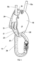
- a belay device 10 for rope comprises a locking cam 11 having a peripheral sector provided with a groove 12 around which is wound the rope 13 in a half-turn.
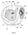
- the cam 11 is mounted for limited rotation around a fixed first axis 14, and is capable of moving between a holding position corresponding to a locking effect of the rope ( figure 8 ) and a spacing position corresponding to an unlocking effect of the rope ( figure 5 ).
- the cam 11 In the retaining position following a fall of the climber, the cam 11 is provided with a boss 15 for catching the rope 13 against a fixed pad 16.
- the stud 16 and the axis 14 are secured by fastening means to the inner wall of a support plate 17, being immobilized in rotation.
- a retractable flange 18 is mounted to tilt on a second axis 19 of the plate 17 to occupy either an open position during the prior installation phase of the rope 13 around the cam 11, or a closed position ( figure 2 ) to trap the rope 13 in the transverse gap formed between the plate 17 and the flange 18.
- the cam 11 further comprises an oblong opening 21 of circular shape centered on the first axis 14, and having a locking notch 22 internal to the right end near the boss 15.
- a trigger pawl 23 is provided between the cam 11 and the plate 17 so as to control the movement of the cam 11.
- the trigger pawl 23 is pivotally mounted about a third axis 24 to be in a position of locking, either in an unlocking position.
- the third axis 24 is carried by the plate 17, and is located in the vicinity of the pad 16 in the passage zone of the rope.
- One of the ends of the trigger pawl 23 is equipped with a detent element 25 that can move in the oblong aperture 21 of the cam 11, while the opposite end is provided with a cooperating control paddle 26. with a compression spring 27 housed in a blind hole of the pad 16.
- the detent element 25 is provided with a roller 25a to facilitate the movement of movement in the opening 21 after unlocking.
- compression spring 27 can be replaced by any other type of return spring, for example a torsion spring inserted on the third axis 24.
- the first adjustment position 1 corresponds to an operation of insurer of the rope leader, allowing the bidirectional pivoting of the trigger pawl 23 between the locking and unlocking positions.
- the passage of the trigger pawl 23 to the unlocking position ( figure 7 ) can intervene automatically when the first strand 13a soft rope 13 is in contact and bearing on the pallet 26 against the counterforce of the spring 27.
- the cam 11 is then released, and can be rotated towards the retaining position by the friction of the rope 13 in the groove 12.
- the second setting position 2 of the device corresponds to an insurer operation of the second roped, or roping.
- the selector 28 immobilizes the trigger pawl 23 in the unlocking position.
- the device then behaves like a blocker.
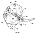
- the belay device 10 further comprises an operating handle 29 mounted limited rotation around a fourth axis 30 carried by the outer face of the plate 17, on the same side as the selector 28.
- a transmission rod 31 is articulated to the handle 29 to form a toggle device having a hinge pin 32 and cooperating with the cam 17 via a mechanical link 36 disengageable.
- the end of the rod 31 opposite the hinge axis 32, is shaped hook 33 engageable with an axis 34 for driving the cam 11 when the mechanical connection 36 is active.
- the drive shaft 34 for this purpose passes through a buttonhole 35 formed in the plate 17, and having a length corresponding to the angular displacement of the cam 11.
- the plate 17 comprises at its base a first orifice 37 situated opposite a second orifice 38 of the flange 18 when the latter occupies the closed position ( figure 2 ).
- a snap hook 39 can then be hooked into the two orifices 37, 38 aligned to connect the apparatus 10 to the belts of the insurer. Moving the flange 18 to the open position is then impossible.
- the stroke of the handle 29 reaches about a 90 ° travel, corresponding to the release of the cam 11.
- the rod 31 comes into support on the handle 29, and its trajectory is then centered on the fourth axis 30 while the mechanical connection 36 is still active.
- the figure 13 corresponds to an anti-panic release, after a continued movement of the operating lever 29 beyond the previous position of the figure 12 , especially towards 96 °.
- the rod 31 moves with the handle 29 so as to interrupt the mechanical connection 36 by escaping the hook 33 with the axis 34.
- the cam 11 becomes free again, and comes to lock the rope against the stud 16.
- the first axis 114 is hollow, being formed by a tubular sleeve extending perpendicularly to the plate 17.
- the cam 11 is provided with an axial bore 40 of circular section and diameter slightly greater than that of the sleeve, which plays the role of a sliding bearing when mounting the rotary cam 11.
- the orifices 137, 138 formed in the plate 17 and the flange 18 of the apparatus 100 are aligned with the socket of the hollow shaft 114 for the passage of the carabiner 39 attachment.
- the other parts of the apparatus 100 are identical to those used in the apparatus 10 of the Figures 1 to 13 .
- the belay device 100 has a compact footprint, following the reduction of the dimensions of the plate 17 and the flange 18 in the direction of the height.
- the insertion of the carabiner 39 attachment in the hollow shaft 114 of the cam 11 positions the apparatus 100 very close to the user, which allows it to give slack more quickly.
Landscapes
- Health & Medical Sciences (AREA)
- General Health & Medical Sciences (AREA)
- Business, Economics & Management (AREA)
- Emergency Management (AREA)
- Emergency Lowering Means (AREA)
- Transmission Devices (AREA)
- Devices For Conveying Motion By Means Of Endless Flexible Members (AREA)
- Ropes Or Cables (AREA)
- Lift-Guide Devices, And Elevator Ropes And Cables (AREA)
- Financial Or Insurance-Related Operations Such As Payment And Settlement (AREA)
Claims (14)
- Seil-Sicherungsgerät, das umfasst:- eine Halteplatte (17), die mit einem festen Klötzchen (16) versehen ist,- einen Nocken (11), der an die Platte begrenzt drehbar um eine erste Achse (14, 114) montiert ist und einen ersten Randabschnitt umfasst, der mit einer Aussparung (12) versehen ist, um die herum das Seil (13) gemäß einer halben Umdrehung aufgerollt ist, welcher Nocken beweglich zwischen einer Rückhalteposition, die dem Festklemmen des Seils (13) durch Klemmwirkung gegen das Klötzchen (16) entspricht, und einer Abstandsposition ist, die es dem Seil (13) ermöglicht, in dem Zwischenraum zwischen dem Nocken (11) und dem Klötzchen (16) frei abgerollt zu werden,dadurch gekennzeichnet, dass der Nocken (11) mit einer Auslöse-Sperrraste (23) verbunden ist, die geeignet ist, entweder eine Verriegelungsposition, die die Blockierung des Nockens (11) in der Abstandsposition sicherstellt, oder in der Folge einer absichtlichen Betätigung, durch die der Nocken (11) freigegeben wird, eine Entriegelungsposition einzunehmen.
- Sicherungsgerät nach Anspruch 1, dadurch gekennzeichnet, dass die Freigabe des Nockens (11) dann erfolgt, wenn das erste, hintere Stück (13a) des Seils (13) an der Auslöse-Sperrraste (23) anliegt.
- Sicherungsgerät nach Anspruch 1, dadurch gekennzeichnet, dass die Auslöse-Sperrraste (23) begrenzt schwenkbar um eine dritte Achse (24) montiert ist und ein Eingriffselement (25) umfasst, das dazu bestimmt ist, in einen Verriegelungsausschnitt (22) des Nockens (11) einzugreifen.
- Sicherungsgerät nach Anspruch 3, dadurch gekennzeichnet, dass die Auslöse-Sperrraste (23) mit einer Steuerungsscheibe (26) versehen ist, die mit einer Feder (27) zusammenwirkt, die die Sperrraste in Richtung auf die Verriegelungsposition zieht, wobei der Druck des ersten Stücks (13a) des Seils auf die Scheibe (26) das Bewegen der Sperrraste in die Entriegelungsposition bewirkt.
- Sicherungs- und Abseilgerät nach Anspruch 3, dadurch gekennzeichnet, dass sich der Verriegelungsausschnitt (22) nahe einer in dem Nocken (11) vorgesehenen länglichen Öffnung (21) befindet, welche Öffnung mit kreisförmigem Querschnitt auf die erste Achse (14, 114) zentriert ist und eine Länge aufweist, die mindestens gleich dem winkligen Ausschlag des Nockens (11) zwischen der Abstands- und der Rückhalteposition ist.
- Sicherungs- und Abseilgerät nach Anspruch 4, dadurch gekennzeichnet, dass sich die Betätigungsscheibe (26) der Sperrraste nahe dem festen Klötzchen (16) befindet, wobei die Feder (27) eine Feder nach Art einer Druckfeder ist, die in einem Sackloch des festen Klötzchens (16) angeordnet ist.
- Sicherungs- und Abseilgerät nach Anspruch 5, dadurch gekennzeichnet, dass das Eingriffselement (25) der Auslöse-Sperrraste (23) mit einer Rolle (25a) zusammenwirkt, die entweder in der länglichen Öffnung (21) des Nockens (11) oder in dem Verriegelungsausschnitt (22) angeordnet ist.
- Sicherungs- und Abseilgerät nach Anspruch 1, dadurch gekennzeichnet, dass die Auslöse-Sperrraste (23) an eine Auswahlvorrichtung (28) gekoppelt ist, die entweder in einer ersten Einstellposition, die einer sichernden Funktion des Seilersten entspricht, oder einer zweiten Einstellposition einstellbar ist, die einer sichernden Funktion des Seilzweiten entspricht.
- Sicherungs- und Abseilgerät nach Anspruch 8, dadurch gekennzeichnet, dass die Auslöse-Sperrraste (23) zwischen dem Nocken (11) und der Innenwand der Platte (17) angeordnet ist, während die Auswahlvorrichtung (28) an die Außenseite der Platte (17) montiert ist.
- Sicherungs- und Abseilgerät nach Anspruch 8, dadurch gekennzeichnet, dass die Auslöse-Sperrraste (23) in der zweiten Einstellposition der Auswahlvorrichtung (28) in Entriegelungsposition blockiert ist, um den Nocken (11) freizugeben.
- Sicherungs- und Abseilgerät nach Anspruch 1, dadurch gekennzeichnet, dass der Nocken (11) mit einem Betätigungshebel (29) verbunden ist, und zwar mittels einer ausrückbaren mechanischen Verbindung (36), die entweder aktiv ist bis zu einer Zwischenposition des Hebels (29), die den Nocken (11) bis in die Abstandsposition mitnimmt, oder inaktiv nach dem Überschreiten der genannten Zwischenposition, die die Freigabe des Nockens (11) und dessen Rückkehr in die Rückhalteposition bewirkt.
- Sicherungs- und Abseilgerät nach Anspruch 11, dadurch gekennzeichnet, dass der Betätigungshebel (29) an einen Übertragungs-Schwingarm (31) angelenkt ist, um eine Kniehebelvorrichtung zu bilden, die mit einer Achse (34) zum Antrieb des Nockens (11) durch die mechanische Verbindung (36) verbunden ist.
- Sicherungs- und Abseilgerät nach Anspruch 1, dadurch gekennzeichnet, dass die erste Achse (114) des drehbaren Nockens (11) zur Durchführung eines Einhänge-Karabiners (39) hohl ist.
- Sicherungs- und Abseilgerät nach einem der vorstehenden Ansprüche, dadurch gekennzeichnet, dass ein wegklappbarer Flansch (18) schwenkbar um eine zweite Achse (19) der Platte (17) montiert ist, um entweder eine offene Position während der vorhergehenden Aufrollphase des Seils um den Nocken (11) oder eine geschlossene Position einzunehmen, um das Seil (13) in dem quergerichteten Zwischenraum zwischen der Platte (17) und dem Flansch (18) festzuhalten.
Applications Claiming Priority (1)
| Application Number | Priority Date | Filing Date | Title |
|---|---|---|---|
| FR0602289A FR2898506B1 (fr) | 2006-03-15 | 2006-03-15 | Appareil multifonctionnel d'assurage pour corde |
Publications (2)
| Publication Number | Publication Date |
|---|---|
| EP1834672A1 EP1834672A1 (de) | 2007-09-19 |
| EP1834672B1 true EP1834672B1 (de) | 2008-10-29 |
Family
ID=36575992
Family Applications (1)
| Application Number | Title | Priority Date | Filing Date |
|---|---|---|---|
| EP07354010A Not-in-force EP1834672B1 (de) | 2006-03-15 | 2007-02-27 | Mehrfunktionsgerät zur Sicherung eines Seils |
Country Status (8)
| Country | Link |
|---|---|
| US (1) | US7845467B2 (de) |
| EP (1) | EP1834672B1 (de) |
| JP (1) | JP2007255709A (de) |
| CN (1) | CN101126434B (de) |
| AT (1) | ATE412452T1 (de) |
| DE (1) | DE602007000205D1 (de) |
| ES (1) | ES2317636T3 (de) |
| FR (1) | FR2898506B1 (de) |
Families Citing this family (88)
| Publication number | Priority date | Publication date | Assignee | Title |
|---|---|---|---|---|
| FR2883938B1 (fr) * | 2005-04-05 | 2009-10-09 | Zedel Soc Par Actions Simplifiee | Mousqueton a verrouillage automatique |
| US9016431B2 (en) * | 2005-06-03 | 2015-04-28 | Great Trango Holdings, Inc. | Load balancing descending device |
| FR2889453B1 (fr) * | 2005-08-04 | 2007-11-30 | Emax Sarl | Dispositif de securite de type assureur/descendeur |
| US20090045010A1 (en) * | 2007-08-15 | 2009-02-19 | Rit Rescue And Escape Systems | Descending device and method of use |
| USD614936S1 (en) * | 2008-06-19 | 2010-05-04 | Zedel | Handle for climbing apparatus |
| FR2938771B1 (fr) * | 2008-11-27 | 2010-12-31 | Zedel | Dispositif bloqueur a came pour l'assurage sur corde fixe |
| WO2010088566A1 (en) * | 2009-02-02 | 2010-08-05 | Ayre William H | Rope handling device with secondary locking feature |
| US9764172B2 (en) * | 2009-03-09 | 2017-09-19 | D B Industries, Llc | Safety device with fall arrest and descending modes |
| US10688323B2 (en) * | 2009-03-09 | 2020-06-23 | D B Industries, Llc | Safety device with fall arrest and descending modes |
| SE533775C2 (sv) * | 2009-05-13 | 2011-01-11 | Initium System Ab | Nedfirningsdon innefattande en hängvippa med utformat bromsorgan |
| DE202009006894U1 (de) * | 2009-05-14 | 2010-04-01 | Skylotec Gmbh | Karabinerhaken mit wenigstens einer rutschfesten Zone |
| IT1396181B1 (it) * | 2009-07-15 | 2012-11-16 | Aludesign Spa | Dispositivo assicuratore |
| US9587434B2 (en) * | 2009-08-21 | 2017-03-07 | Rory Frick | Ladder |
| US8348016B2 (en) | 2009-08-26 | 2013-01-08 | Lewis Richard W | Descender with fall arrest and controlled rate of descent |
| FR2950536B1 (fr) * | 2009-09-25 | 2011-10-07 | Zedel | Dispositif d'assurance autobloquant pour corde |
| JP5437296B2 (ja) * | 2010-03-01 | 2014-03-12 | 金治 大塩 | クライミング用ロープの制動装置 |
| CN101870437B (zh) * | 2010-05-19 | 2013-03-13 | 广州四航岩土技术工程有限公司 | 电动攀登器及其应用设备 |
| FR2961709B1 (fr) * | 2010-06-23 | 2012-12-07 | Zedel | Appareil bloqueur descendeur pour la remontee et la descente sur corde |
| FR2962724B1 (fr) * | 2010-07-16 | 2012-08-03 | Zedel | Poulie a bloqueur deverrouillable |
| CN101940165A (zh) * | 2010-08-22 | 2011-01-12 | 叶林斌 | 紧急锁止式宠物绳 |
| US12204087B2 (en) | 2010-10-28 | 2025-01-21 | Endochoice, Inc. | Optical systems for multi-sensor endoscopes |
| IT1403628B1 (it) * | 2011-01-13 | 2013-10-31 | Aludesign Spa | Dispositivo assicuratore e discensore |
| CN103619422B (zh) * | 2011-05-18 | 2016-05-11 | 普罗帝克保护技术有限公司 | 具有防恐慌功能的自制动下降器 |
| GB2492621B (en) * | 2011-07-08 | 2014-05-21 | Gripple Ltd | Gripping arrangement and gripping assembly |
| EP2554219B1 (de) * | 2011-08-03 | 2023-11-29 | Camp S.p.A. | Unterstützte Sicherheitsverriegelungsvorrichtung mit einer Antipanikvorrichtung |
| US8733504B2 (en) * | 2012-01-17 | 2014-05-27 | Kirk Mauthner | Method and apparatus for a compact descender |
| DE102012207223B3 (de) * | 2012-04-30 | 2013-09-26 | Bornack Gmbh & Co. Kg | Sicherungsvorrichtung |
| FR2990873B1 (fr) * | 2012-05-22 | 2016-12-09 | Zedel | Bloqueur de longe a corps mobile en rotation |
| FR2998182B1 (fr) * | 2012-11-16 | 2015-06-26 | Zedel | Appareil de securite sur corde a verrouillage sous charge |
| FR3000900B1 (fr) * | 2013-01-15 | 2015-02-27 | Zedel | Appareil de securite antichute sur corde avec fonction bloqueur |
| FR3000899B1 (fr) | 2013-01-15 | 2015-06-26 | Zedel | Appareil de securite antichute et blocage sur corde |
| FR3000898B1 (fr) * | 2013-01-16 | 2015-06-26 | Zedel | Appareil de securite sur corde a voyant indicateur de l'etat indicateur de l'etat de fermeture des flasques |
| US9623269B2 (en) | 2013-03-14 | 2017-04-18 | Black Diamond Equipment, Ltd. | Systems for assisted braking belay with a cam-clutch mechanism |
| USD739212S1 (en) | 2013-05-10 | 2015-09-22 | D B Industries, Llc | Housing of a rope grab |
| USD764258S1 (en) * | 2013-05-10 | 2016-08-23 | D B Industries, Llc | Housing of a rope grab |
| USD746125S1 (en) * | 2013-05-10 | 2015-12-29 | D B Industries, Llc | Fixed side plate of a rope grab |
| FR3011475B1 (fr) * | 2013-10-07 | 2016-03-04 | Simond Ets | Descendeur-assureur autobloquant |
| GB2522179B (en) * | 2013-11-14 | 2019-02-13 | Int Safety Components Ltd | Improvements in and relating to rope descenders |
| FR3022232B1 (fr) * | 2014-06-11 | 2022-03-04 | Pascal Ollivier | Appareil de suspension d'une charge a un filin |
| FR3032354A1 (fr) * | 2015-02-11 | 2016-08-12 | Zedel | Dispositif assureur descendeur sur corde a demultiplication et blocage anti-panique |
| US10583315B2 (en) * | 2015-04-07 | 2020-03-10 | Harken, Incorporated | High load descender with adaptive release linkage |
| US11660475B2 (en) | 2015-04-07 | 2023-05-30 | Harken, Incorporated | High load descender with adaptive release linkage |
| EP3280499A4 (de) | 2015-04-07 | 2018-11-21 | Harken, Incorporated | Abseilgerät für hohe lasten mit adaptiver auslösungsverbindung |
| CA2928081C (en) * | 2015-04-24 | 2018-09-18 | Buckingham Manufacturing Company, Inc. | Cam assembly for use with pole climbing fall restriction device |
| USD765497S1 (en) * | 2015-05-06 | 2016-09-06 | Zedel | Carabiner |
| US9604079B2 (en) | 2015-07-21 | 2017-03-28 | Merritt Arboreal Design, Inc. | On-rope work positioning device |
| FR3039410B1 (fr) * | 2015-07-31 | 2018-09-07 | Zedel | Dispositif d'assurage sur corde utilisable en mode assureur et en moulinette |
| US20170050055A1 (en) * | 2015-08-23 | 2017-02-23 | Patrick Michael Spydell, JR. | Auto-Blocking Rappelling and Belaying Device |
| US9750959B2 (en) * | 2015-10-21 | 2017-09-05 | Msa Technology, Llc | Cable grab device |
| TWM521595U (zh) * | 2015-11-16 | 2016-05-11 | yi-shun Shi | 不用按開關可即時鎖住及釋放一繩子之裝置 |
| USD827418S1 (en) | 2015-12-07 | 2018-09-04 | Daniel Austin | Rope line anchor with hook |
| USD786049S1 (en) * | 2015-12-07 | 2017-05-09 | Daniel Austin | Anchor hook |
| USD790327S1 (en) * | 2015-12-15 | 2017-06-27 | Doskocil Manufacturing Company, Inc. | Leash clip |
| USD788572S1 (en) * | 2016-02-10 | 2017-06-06 | Tenacious Holdings, Inc. | Carabiner |
| US10315056B2 (en) | 2016-07-11 | 2019-06-11 | Great Trango Holdings, Inc. | Belay device |
| CN106081974A (zh) * | 2016-08-26 | 2016-11-09 | 江铃汽车股份有限公司 | 一种通过钢丝绳传输小车上的快速夹钩装置 |
| CN110072595B (zh) | 2016-12-16 | 2020-06-12 | 3M创新有限公司 | 具有制动系统的坠落保护设备 |
| US10035028B1 (en) * | 2017-01-04 | 2018-07-31 | Mallory Safety+Supply | Emergency descender device |
| USD814274S1 (en) * | 2017-05-10 | 2018-04-03 | Infinity Canopy, Inc. | Connector for canopy system |
| USD822465S1 (en) * | 2017-05-10 | 2018-07-10 | Infinity Canopy, Inc. | Cable eyelet |
| US10987525B2 (en) * | 2017-05-22 | 2021-04-27 | Cmc Rescue, Inc. | Descending apparatus and methods for use of same |
| DE102017113778A1 (de) | 2017-06-21 | 2018-12-27 | Dee Luxe Sportartikel Handels Gmbh | Schnellschnürsystem sowie damit ausgestatteter Schuh |
| IT201700111007A1 (it) * | 2017-10-04 | 2019-04-04 | Camp Spa | Discensore |
| AU201814138S (en) * | 2018-02-02 | 2018-08-15 | Furla Spa | Snap Ring |
| CN108497994B (zh) * | 2018-04-09 | 2020-07-14 | 山东海瑞林装饰工程有限公司 | 一种清洗玻璃幕墙的自动化吊具 |
| FR3080045B1 (fr) * | 2018-04-11 | 2020-05-15 | Zedel | Descendeur autobloquant a poignee debrayable |
| US11524185B2 (en) * | 2019-04-01 | 2022-12-13 | Cmc Rescue, Inc. | Closure system |
| US11648967B2 (en) * | 2019-04-30 | 2023-05-16 | Honeywell International, Inc. | Fall protection locking systems |
| FR3096899B1 (fr) * | 2019-06-06 | 2021-06-25 | Zedel | Poulie double |
| US11331540B2 (en) * | 2019-10-01 | 2022-05-17 | S. Kevin Bingham | Rope climbing mechanism with controlled descent clutch body including pivotally associated descent lever |
| USD948996S1 (en) * | 2019-11-13 | 2022-04-19 | Shurtech Brands, Llc | Hook |
| CN110731291B (zh) * | 2019-12-02 | 2022-06-21 | 漳澳国际有限公司 | 单体贝类养殖箱连接组件 |
| CN110975179B (zh) * | 2019-12-10 | 2021-09-03 | 浙江华电器材检测研究所有限公司 | 一种防慌乱的速降器 |
| EP4076682B1 (de) * | 2019-12-19 | 2025-07-16 | Rapid Rappel Technology As | Sinkkontrollvorrichtung |
| USD932879S1 (en) * | 2020-02-11 | 2021-10-12 | Daniel Austin | Adjustable hook |
| USD933463S1 (en) * | 2020-02-11 | 2021-10-19 | Daniel Austin | Fender hook |
| IT202000006760A1 (it) | 2020-03-31 | 2021-10-01 | Prograde S R L | Apparecchiatura di sicurezza per arrampicata sportiva. |
| IT202000006769A1 (it) | 2020-03-31 | 2021-10-01 | Prograde S R L | Apparecchiatura di sicurezza per arrampicata sportiva. |
| CN113384826A (zh) * | 2020-07-08 | 2021-09-14 | 浙江唯海科技有限公司 | 单手控制自保护下降器 |
| US12017895B2 (en) * | 2020-07-16 | 2024-06-25 | Merritt Arboreal Design, Inc. | Load support device and system |
| TWI803967B (zh) | 2020-10-19 | 2023-06-01 | 宏達國際電子股份有限公司 | 握帶與手把總成 |
| CN113071720B (zh) * | 2021-03-24 | 2022-08-30 | 哈尔滨工业大学 | 一种工具包转移绳索缓释装置 |
| US11339852B1 (en) | 2021-04-27 | 2022-05-24 | Daniel Austin | Adjustable hook with strap |
| DE102021002712B3 (de) * | 2021-05-25 | 2022-06-02 | Andreas Schuhmacher | Seilbremse zur Befestigung in einem Sicherungspunkt |
| USD951077S1 (en) * | 2021-06-25 | 2022-05-10 | Binbin Lv | Hook |
| IT202100025394A1 (it) * | 2021-10-04 | 2023-04-04 | Aludesign Spa | Dispositivo multifunzione dotato di una camma di bloccaggio e di una puleggia per una fune di sicurezza |
| US20230158348A1 (en) * | 2021-11-19 | 2023-05-25 | Checkmate Lifting & Safety Ltd | Cable sleeve |
| CN117231618B (zh) * | 2023-09-25 | 2026-03-24 | 杭州汇创进出口有限公司 | 一种快捷自锁器 |
Family Cites Families (7)
| Publication number | Priority date | Publication date | Assignee | Title |
|---|---|---|---|---|
| US2931466A (en) * | 1958-04-01 | 1960-04-05 | Allenbaugh Ralph | Safety locking mechanism |
| DK148348C (da) * | 1983-02-11 | 1985-11-04 | Berendsen Sophus Marine As | Laasemekanisme til fastlaasning af et tov, en line eller et lignende langstrakt boejeligt traekorgan |
| FR2647099B1 (fr) | 1989-05-19 | 1991-07-19 | Petzl Ets | Dispositif d'assurance autobloquant pour corde |
| FR2721522B1 (fr) * | 1994-06-23 | 1996-08-14 | Zedel | Descendeur débrayable à autoblocage de la corde. |
| FR2721523B1 (fr) | 1994-06-23 | 1996-08-14 | Zedel | Descendeur à verrouillage de la poulie pour le blocage permanent de la corde. |
| AUPN864296A0 (en) * | 1996-03-13 | 1996-04-04 | Rogelja, Boris | Descender |
| FR2748078B1 (fr) * | 1996-04-25 | 1998-06-12 | Zedel | Poulie a flasque pivotant et a bloqueur integre |
-
2006
- 2006-03-15 FR FR0602289A patent/FR2898506B1/fr not_active Expired - Fee Related
-
2007
- 2007-02-27 EP EP07354010A patent/EP1834672B1/de not_active Not-in-force
- 2007-02-27 ES ES07354010T patent/ES2317636T3/es active Active
- 2007-02-27 DE DE602007000205T patent/DE602007000205D1/de not_active Expired - Fee Related
- 2007-02-27 AT AT07354010T patent/ATE412452T1/de active
- 2007-03-07 US US11/714,738 patent/US7845467B2/en not_active Expired - Fee Related
- 2007-03-15 JP JP2007066869A patent/JP2007255709A/ja not_active Withdrawn
- 2007-03-15 CN CN2007101097362A patent/CN101126434B/zh not_active Expired - Fee Related
Also Published As
| Publication number | Publication date |
|---|---|
| CN101126434A (zh) | 2008-02-20 |
| ES2317636T3 (es) | 2009-04-16 |
| US20070215411A1 (en) | 2007-09-20 |
| FR2898506B1 (fr) | 2008-05-30 |
| EP1834672A1 (de) | 2007-09-19 |
| CN101126434B (zh) | 2010-07-21 |
| JP2007255709A (ja) | 2007-10-04 |
| DE602007000205D1 (de) | 2008-12-11 |
| ATE412452T1 (de) | 2008-11-15 |
| FR2898506A1 (fr) | 2007-09-21 |
| US7845467B2 (en) | 2010-12-07 |
Similar Documents
| Publication | Publication Date | Title |
|---|---|---|
| EP1834672A1 (de) | Mehrfunktionsgerät zur Sicherung eines Seils | |
| EP0688581B1 (de) | Entkuppelbares selbstblockierendes Abseilgerät | |
| EP0593369B1 (de) | Sicherheitsabseilvorrichtung | |
| EP2191870B1 (de) | Blockiervorrichtung mit Nocke zur Absicherung an einem festen Seil | |
| EP0398819B1 (de) | Selbstbremsende Seilsicherheitsvorrichtung | |
| EP3056248B1 (de) | Sicherungs- und abseilgerät über ein seil mit übersetzung und anti-panik-blockade | |
| EP1380320B1 (de) | Absturzgesichertes Führungsgerät für eine feste Leine | |
| EP2735341B1 (de) | Seilsicherungsgerät mit Verschlussmöglichkeit unter Belastung | |
| EP1710456B1 (de) | Selbstverriegelnder Karabinerhaken | |
| EP2301631B1 (de) | Selbstblockierende Sicherheitsvorrichtung für ein Seil | |
| EP1465507B1 (de) | Schnalle zur selbstverriegelung und einstellungsfestlegung eines gürtels | |
| EP0416079A1 (de) | Selbstblockierende abseilvorrichtung mit zwei blockierstellungen. | |
| EP2018894A1 (de) | Selbstblockierendes Abseilgerät mit entkoppelbarem Griff | |
| FR2751233A1 (fr) | Dispositif d'arret automatique de chute pour des personnels travaillant en hauteur | |
| EP0752255A1 (de) | Bewegliches Absturzsicherungsgerät für flexibles Rettungsseil | |
| FR2962724A1 (fr) | Poulie a bloqueur deverrouillable | |
| EP3141285B1 (de) | Selbstblockierende sicherheitsvorrichtung für kletterseil | |
| EP3124081B1 (de) | Vorrichtung zur sicherung am seil für den einsatz als sicherung und als toprope | |
| FR2721523A1 (fr) | Descendeur à verrouillage de la poulie pour le blocage permanent de la corde. | |
| FR2904564A1 (fr) | Appareil assureur et descendeur pour corde | |
| FR3057170A1 (fr) | Dispositif antichute a frein d'enroulement | |
| FR3141350A1 (fr) | Dispositif antichute mobile | |
| FR2814082A1 (fr) | Dispositif de securite pour controler la descente et/ou le hissage d'une charge sur une corde | |
| FR2924617A1 (fr) | Enrouleur a deroulement limite | |
| CA2029957A1 (fr) | Appareil qui neutralise la tension de rappel des ceintures de securite a enrouleur automatique |
Legal Events
| Date | Code | Title | Description |
|---|---|---|---|
| PUAI | Public reference made under article 153(3) epc to a published international application that has entered the european phase |
Free format text: ORIGINAL CODE: 0009012 |
|
| AK | Designated contracting states |
Kind code of ref document: A1 Designated state(s): AT BE BG CH CY CZ DE DK EE ES FI FR GB GR HU IE IS IT LI LT LU LV MC NL PL PT RO SE SI SK TR |
|
| AX | Request for extension of the european patent |
Extension state: AL BA HR MK YU |
|
| 17P | Request for examination filed |
Effective date: 20071208 |
|
| 17Q | First examination report despatched |
Effective date: 20080130 |
|
| AKX | Designation fees paid |
Designated state(s): AT BE BG CH CY CZ DE DK EE ES FI FR GB GR HU IE IS IT LI LT LU LV MC NL PL PT RO SE SI SK TR |
|
| GRAP | Despatch of communication of intention to grant a patent |
Free format text: ORIGINAL CODE: EPIDOSNIGR1 |
|
| GRAS | Grant fee paid |
Free format text: ORIGINAL CODE: EPIDOSNIGR3 |
|
| GRAA | (expected) grant |
Free format text: ORIGINAL CODE: 0009210 |
|
| AK | Designated contracting states |
Kind code of ref document: B1 Designated state(s): AT BE BG CH CY CZ DE DK EE ES FI FR GB GR HU IE IS IT LI LT LU LV MC NL PL PT RO SE SI SK TR |
|
| REG | Reference to a national code |
Ref country code: GB Ref legal event code: FG4D Free format text: NOT ENGLISH |
|
| REG | Reference to a national code |
Ref country code: CH Ref legal event code: EP |
|
| REG | Reference to a national code |
Ref country code: IE Ref legal event code: FG4D Free format text: LANGUAGE OF EP DOCUMENT: FRENCH |
|
| REF | Corresponds to: |
Ref document number: 602007000205 Country of ref document: DE Date of ref document: 20081211 Kind code of ref document: P |
|
| REG | Reference to a national code |
Ref country code: CH Ref legal event code: NV Representative=s name: CABINET ROLAND NITHARDT CONSEILS EN PROPRIETE INDU |
|
| NLV1 | Nl: lapsed or annulled due to failure to fulfill the requirements of art. 29p and 29m of the patents act | ||
| REG | Reference to a national code |
Ref country code: ES Ref legal event code: FG2A Ref document number: 2317636 Country of ref document: ES Kind code of ref document: T3 |
|
| LTIE | Lt: invalidation of european patent or patent extension |
Effective date: 20081029 |
|
| PG25 | Lapsed in a contracting state [announced via postgrant information from national office to epo] |
Ref country code: BG Free format text: LAPSE BECAUSE OF FAILURE TO SUBMIT A TRANSLATION OF THE DESCRIPTION OR TO PAY THE FEE WITHIN THE PRESCRIBED TIME-LIMIT Effective date: 20090129 Ref country code: LT Free format text: LAPSE BECAUSE OF FAILURE TO SUBMIT A TRANSLATION OF THE DESCRIPTION OR TO PAY THE FEE WITHIN THE PRESCRIBED TIME-LIMIT Effective date: 20081029 |
|
| PGFP | Annual fee paid to national office [announced via postgrant information from national office to epo] |
Ref country code: AT Payment date: 20090211 Year of fee payment: 3 Ref country code: ES Payment date: 20090317 Year of fee payment: 3 |
|
| PG25 | Lapsed in a contracting state [announced via postgrant information from national office to epo] |
Ref country code: IS Free format text: LAPSE BECAUSE OF FAILURE TO SUBMIT A TRANSLATION OF THE DESCRIPTION OR TO PAY THE FEE WITHIN THE PRESCRIBED TIME-LIMIT Effective date: 20090228 Ref country code: PL Free format text: LAPSE BECAUSE OF FAILURE TO SUBMIT A TRANSLATION OF THE DESCRIPTION OR TO PAY THE FEE WITHIN THE PRESCRIBED TIME-LIMIT Effective date: 20081029 Ref country code: LV Free format text: LAPSE BECAUSE OF FAILURE TO SUBMIT A TRANSLATION OF THE DESCRIPTION OR TO PAY THE FEE WITHIN THE PRESCRIBED TIME-LIMIT Effective date: 20081029 Ref country code: FI Free format text: LAPSE BECAUSE OF FAILURE TO SUBMIT A TRANSLATION OF THE DESCRIPTION OR TO PAY THE FEE WITHIN THE PRESCRIBED TIME-LIMIT Effective date: 20081029 Ref country code: SI Free format text: LAPSE BECAUSE OF FAILURE TO SUBMIT A TRANSLATION OF THE DESCRIPTION OR TO PAY THE FEE WITHIN THE PRESCRIBED TIME-LIMIT Effective date: 20081029 Ref country code: PT Free format text: LAPSE BECAUSE OF FAILURE TO SUBMIT A TRANSLATION OF THE DESCRIPTION OR TO PAY THE FEE WITHIN THE PRESCRIBED TIME-LIMIT Effective date: 20090330 Ref country code: NL Free format text: LAPSE BECAUSE OF FAILURE TO SUBMIT A TRANSLATION OF THE DESCRIPTION OR TO PAY THE FEE WITHIN THE PRESCRIBED TIME-LIMIT Effective date: 20081029 |
|
| PGFP | Annual fee paid to national office [announced via postgrant information from national office to epo] |
Ref country code: CZ Payment date: 20090213 Year of fee payment: 3 Ref country code: DE Payment date: 20090219 Year of fee payment: 3 |
|
| REG | Reference to a national code |
Ref country code: IE Ref legal event code: FD4D |
|
| PG25 | Lapsed in a contracting state [announced via postgrant information from national office to epo] |
Ref country code: IE Free format text: LAPSE BECAUSE OF FAILURE TO SUBMIT A TRANSLATION OF THE DESCRIPTION OR TO PAY THE FEE WITHIN THE PRESCRIBED TIME-LIMIT Effective date: 20081029 Ref country code: RO Free format text: LAPSE BECAUSE OF FAILURE TO SUBMIT A TRANSLATION OF THE DESCRIPTION OR TO PAY THE FEE WITHIN THE PRESCRIBED TIME-LIMIT Effective date: 20081029 Ref country code: EE Free format text: LAPSE BECAUSE OF FAILURE TO SUBMIT A TRANSLATION OF THE DESCRIPTION OR TO PAY THE FEE WITHIN THE PRESCRIBED TIME-LIMIT Effective date: 20081029 Ref country code: DK Free format text: LAPSE BECAUSE OF FAILURE TO SUBMIT A TRANSLATION OF THE DESCRIPTION OR TO PAY THE FEE WITHIN THE PRESCRIBED TIME-LIMIT Effective date: 20081029 |
|
| BERE | Be: lapsed |
Owner name: ZEDEL Effective date: 20090228 |
|
| PG25 | Lapsed in a contracting state [announced via postgrant information from national office to epo] |
Ref country code: SE Free format text: LAPSE BECAUSE OF FAILURE TO SUBMIT A TRANSLATION OF THE DESCRIPTION OR TO PAY THE FEE WITHIN THE PRESCRIBED TIME-LIMIT Effective date: 20090129 |
|
| PLBE | No opposition filed within time limit |
Free format text: ORIGINAL CODE: 0009261 |
|
| STAA | Information on the status of an ep patent application or granted ep patent |
Free format text: STATUS: NO OPPOSITION FILED WITHIN TIME LIMIT |
|
| PG25 | Lapsed in a contracting state [announced via postgrant information from national office to epo] |
Ref country code: SK Free format text: LAPSE BECAUSE OF FAILURE TO SUBMIT A TRANSLATION OF THE DESCRIPTION OR TO PAY THE FEE WITHIN THE PRESCRIBED TIME-LIMIT Effective date: 20081029 Ref country code: MC Free format text: LAPSE BECAUSE OF NON-PAYMENT OF DUE FEES Effective date: 20090228 |
|
| 26N | No opposition filed |
Effective date: 20090730 |
|
| PG25 | Lapsed in a contracting state [announced via postgrant information from national office to epo] |
Ref country code: BE Free format text: LAPSE BECAUSE OF NON-PAYMENT OF DUE FEES Effective date: 20090228 |
|
| PG25 | Lapsed in a contracting state [announced via postgrant information from national office to epo] |
Ref country code: GR Free format text: LAPSE BECAUSE OF FAILURE TO SUBMIT A TRANSLATION OF THE DESCRIPTION OR TO PAY THE FEE WITHIN THE PRESCRIBED TIME-LIMIT Effective date: 20090130 |
|
| PG25 | Lapsed in a contracting state [announced via postgrant information from national office to epo] |
Ref country code: CZ Free format text: LAPSE BECAUSE OF NON-PAYMENT OF DUE FEES Effective date: 20100227 |
|
| PG25 | Lapsed in a contracting state [announced via postgrant information from national office to epo] |
Ref country code: DE Free format text: LAPSE BECAUSE OF NON-PAYMENT OF DUE FEES Effective date: 20100901 |
|
| REG | Reference to a national code |
Ref country code: ES Ref legal event code: FD2A Effective date: 20110308 |
|
| PG25 | Lapsed in a contracting state [announced via postgrant information from national office to epo] |
Ref country code: LU Free format text: LAPSE BECAUSE OF NON-PAYMENT OF DUE FEES Effective date: 20090227 |
|
| PGFP | Annual fee paid to national office [announced via postgrant information from national office to epo] |
Ref country code: IT Payment date: 20110219 Year of fee payment: 5 |
|
| PGRI | Patent reinstated in contracting state [announced from national office to epo] |
Ref country code: IT Effective date: 20110501 |
|
| PG25 | Lapsed in a contracting state [announced via postgrant information from national office to epo] |
Ref country code: HU Free format text: LAPSE BECAUSE OF FAILURE TO SUBMIT A TRANSLATION OF THE DESCRIPTION OR TO PAY THE FEE WITHIN THE PRESCRIBED TIME-LIMIT Effective date: 20090430 |
|
| PG25 | Lapsed in a contracting state [announced via postgrant information from national office to epo] |
Ref country code: ES Free format text: LAPSE BECAUSE OF NON-PAYMENT OF DUE FEES Effective date: 20110307 |
|
| PGFP | Annual fee paid to national office [announced via postgrant information from national office to epo] |
Ref country code: GB Payment date: 20110223 Year of fee payment: 5 |
|
| PG25 | Lapsed in a contracting state [announced via postgrant information from national office to epo] |
Ref country code: TR Free format text: LAPSE BECAUSE OF FAILURE TO SUBMIT A TRANSLATION OF THE DESCRIPTION OR TO PAY THE FEE WITHIN THE PRESCRIBED TIME-LIMIT Effective date: 20081029 |
|
| PG25 | Lapsed in a contracting state [announced via postgrant information from national office to epo] |
Ref country code: ES Free format text: LAPSE BECAUSE OF NON-PAYMENT OF DUE FEES Effective date: 20100228 Ref country code: CY Free format text: LAPSE BECAUSE OF FAILURE TO SUBMIT A TRANSLATION OF THE DESCRIPTION OR TO PAY THE FEE WITHIN THE PRESCRIBED TIME-LIMIT Effective date: 20081029 |
|
| REG | Reference to a national code |
Ref country code: CH Ref legal event code: PL |
|
| PG25 | Lapsed in a contracting state [announced via postgrant information from national office to epo] |
Ref country code: CH Free format text: LAPSE BECAUSE OF NON-PAYMENT OF DUE FEES Effective date: 20110228 Ref country code: LI Free format text: LAPSE BECAUSE OF NON-PAYMENT OF DUE FEES Effective date: 20110228 |
|
| PGFP | Annual fee paid to national office [announced via postgrant information from national office to epo] |
Ref country code: FR Payment date: 20120323 Year of fee payment: 6 |
|
| GBPC | Gb: european patent ceased through non-payment of renewal fee |
Effective date: 20120227 |
|
| PG25 | Lapsed in a contracting state [announced via postgrant information from national office to epo] |
Ref country code: IT Free format text: LAPSE BECAUSE OF NON-PAYMENT OF DUE FEES Effective date: 20120227 |
|
| REG | Reference to a national code |
Ref country code: AT Ref legal event code: MM01 Ref document number: 412452 Country of ref document: AT Kind code of ref document: T Effective date: 20120227 |
|
| PG25 | Lapsed in a contracting state [announced via postgrant information from national office to epo] |
Ref country code: AT Free format text: LAPSE BECAUSE OF NON-PAYMENT OF DUE FEES Effective date: 20120227 Ref country code: GB Free format text: LAPSE BECAUSE OF NON-PAYMENT OF DUE FEES Effective date: 20120227 |
|
| REG | Reference to a national code |
Ref country code: FR Ref legal event code: ST Effective date: 20131031 |
|
| PG25 | Lapsed in a contracting state [announced via postgrant information from national office to epo] |
Ref country code: FR Free format text: LAPSE BECAUSE OF NON-PAYMENT OF DUE FEES Effective date: 20130228 |