EP3056455B1 - Unite de chaines d'approvisionnement - Google Patents
Unite de chaines d'approvisionnement Download PDFInfo
- Publication number
- EP3056455B1 EP3056455B1 EP16155267.4A EP16155267A EP3056455B1 EP 3056455 B1 EP3056455 B1 EP 3056455B1 EP 16155267 A EP16155267 A EP 16155267A EP 3056455 B1 EP3056455 B1 EP 3056455B1
- Authority
- EP
- European Patent Office
- Prior art keywords
- feed chain
- driver
- chain
- drivers
- unit according
- Prior art date
- Legal status (The legal status is an assumption and is not a legal conclusion. Google has not performed a legal analysis and makes no representation as to the accuracy of the status listed.)
- Active
Links
Images





Classifications
-
- B—PERFORMING OPERATIONS; TRANSPORTING
- B65—CONVEYING; PACKING; STORING; HANDLING THIN OR FILAMENTARY MATERIAL
- B65G—TRANSPORT OR STORAGE DEVICES, e.g. CONVEYORS FOR LOADING OR TIPPING, SHOP CONVEYOR SYSTEMS OR PNEUMATIC TUBE CONVEYORS
- B65G19/00—Conveyors comprising an impeller or a series of impellers carried by an endless traction element and arranged to move articles or materials over a supporting surface or underlying material, e.g. endless scraper conveyors
- B65G19/18—Details
- B65G19/22—Impellers, e.g. push-plates, scrapers; Guiding means therefor
- B65G19/24—Attachment of impellers to traction element
- B65G19/245—Attachment of impellers to traction element for article conveyors, e.g. for container conveyors
-
- B—PERFORMING OPERATIONS; TRANSPORTING
- B65—CONVEYING; PACKING; STORING; HANDLING THIN OR FILAMENTARY MATERIAL
- B65B—MACHINES, APPARATUS OR DEVICES FOR, OR METHODS OF, PACKAGING ARTICLES OR MATERIALS; UNPACKING
- B65B35/00—Supplying, feeding, arranging or orientating articles to be packaged
- B65B35/10—Feeding, e.g. conveying, single articles
- B65B35/24—Feeding, e.g. conveying, single articles by endless belts or chains
-
- B—PERFORMING OPERATIONS; TRANSPORTING
- B65—CONVEYING; PACKING; STORING; HANDLING THIN OR FILAMENTARY MATERIAL
- B65B—MACHINES, APPARATUS OR DEVICES FOR, OR METHODS OF, PACKAGING ARTICLES OR MATERIALS; UNPACKING
- B65B35/00—Supplying, feeding, arranging or orientating articles to be packaged
- B65B35/30—Arranging and feeding articles in groups
- B65B35/44—Arranging and feeding articles in groups by endless belts or chains
-
- B—PERFORMING OPERATIONS; TRANSPORTING
- B65—CONVEYING; PACKING; STORING; HANDLING THIN OR FILAMENTARY MATERIAL
- B65B—MACHINES, APPARATUS OR DEVICES FOR, OR METHODS OF, PACKAGING ARTICLES OR MATERIALS; UNPACKING
- B65B59/00—Arrangements to enable machines to handle articles of different sizes, to produce packages of different sizes, to vary the contents of packages, to handle different types of packaging material, or to give access for cleaning or maintenance purposes
- B65B59/005—Adjustable conveying means
-
- B—PERFORMING OPERATIONS; TRANSPORTING
- B65—CONVEYING; PACKING; STORING; HANDLING THIN OR FILAMENTARY MATERIAL
- B65B—MACHINES, APPARATUS OR DEVICES FOR, OR METHODS OF, PACKAGING ARTICLES OR MATERIALS; UNPACKING
- B65B9/00—Enclosing successive articles, or quantities of material, e.g. liquids or semiliquids, in flat, folded, or tubular webs of flexible sheet material; Subdividing filled flexible tubes to form packages
- B65B9/06—Enclosing successive articles, or quantities of material, in a longitudinally-folded web, or in a web folded into a tube about the articles or quantities of material placed upon it
-
- B—PERFORMING OPERATIONS; TRANSPORTING
- B65—CONVEYING; PACKING; STORING; HANDLING THIN OR FILAMENTARY MATERIAL
- B65B—MACHINES, APPARATUS OR DEVICES FOR, OR METHODS OF, PACKAGING ARTICLES OR MATERIALS; UNPACKING
- B65B51/00—Devices for, or methods of, sealing or securing package folds or closures; Devices for gathering or twisting wrappers, or necks of bags
- B65B51/10—Applying or generating heat or pressure or combinations thereof
- B65B51/26—Devices specially adapted for producing transverse or longitudinal seams in webs or tubes
- B65B51/30—Devices, e.g. jaws, for applying pressure and heat, e.g. for subdividing filled tubes
- B65B51/306—Counter-rotating devices
-
- B—PERFORMING OPERATIONS; TRANSPORTING
- B65—CONVEYING; PACKING; STORING; HANDLING THIN OR FILAMENTARY MATERIAL
- B65B—MACHINES, APPARATUS OR DEVICES FOR, OR METHODS OF, PACKAGING ARTICLES OR MATERIALS; UNPACKING
- B65B59/00—Arrangements to enable machines to handle articles of different sizes, to produce packages of different sizes, to vary the contents of packages, to handle different types of packaging material, or to give access for cleaning or maintenance purposes
- B65B59/001—Arrangements to enable adjustments related to the product to be packaged
Definitions
- the invention relates to a supply chain unit, as used in particular in tubular bag machines for the defined supply of the products to be packaged.
- tubular bags are formed from a running, initially flat, film web by bending the longitudinal edges of the film web - usually horizontally or slightly obliquely downwards - against each other and sealing them longitudinally against each other.
- the products rest on a support surface and are usually pushed forward along the support surface by the carriers attached to the supply chain at regular intervals.
- the feed chain has to be removed from the inner cross section of the resulting film tube before the point at which the longitudinal edges of the film web run against each other be led out, usually by the supply chain dives down, with downstream of the supply chain unit often little space is available.
- feed chain instead of a feed chain, other feed conveyors may be used, for which reason the imported feed chain term is used for the purposes of the present invention, but this may be any type of feed conveyor capable of delivering the products in the necessary defined manner Way in the resulting film tube hineinzuessorn, be it a conveyor belt on the flat top of the products without form fit for further transport only rest, be it timing belt or link chains or the like.
- the driver must also be physically different in adaptation to the shape of the product, and possibly the side guides that prevent that the product runs down the side of the feed chain, be readjusted in their distance from each other.
- a supply chain unit known to which drivers are attached each consisting of two parts, namely consisting of the base part and driver part, are formed so that the driver part can be detached from the base part and replaced with a product-specific other driver part.
- the base parts are not attached to the (continuous) conveyor chain, but part of the conveyor chain, by each forming a link of the conveyor chain.
- the base parts can not be detached from the conveyor chain and accordingly not be changed in their position on the conveyor chain.
- the feed chain runs endlessly in a vertical orbital plane, wherein the drivers protrude radially outward in this orbital plane.
- the driver For the format change so either the entire driver must be easy to dismantle and mount on the supply chain, or the driver consists of a base part, which always remains firmly attached to the supply chain and a contrast easily mountable and removable driver part, which on the base part for Example plugged and locked or can be easily changed in other ways.
- the base part is in this case usually not on the upper edge of the support surface for the products before.
- the drivers and in particular their attachment relative to the supply chain are designed so that either to disengage the entire driver of the supply chain or at least a part, in particular of the driver part of the base part of the driver, no disassembly work on the tubular bag machine - except the dismantled Carrier - must be carried out.
- the drivers or parts of the driver in the circulation plane to the outside, the top strand so up, deducted and / or put on.
- driver consist of base part and thereon easily releasably attached driver part, wherein the driver part is attached to the base part, e.g. by simply plugging and thereby locking the two parts against each other, and vice versa by simply pulling the driver upwards this can be dismantled.
- the drivers must preferably be articulated about a transverse pivot axis within the driver or against the supply chain and be guided with a corresponding slotted guide in the area of incipient guiding around the pulley.
- the supply chain facing part of the one-piece driver or the base part of a two-piece driver in the running direction of the supply chain extending guide leg - for example, in addition to the actual feed chain - which cooperates positively at the end of the transport path with an underlying guide rail, in that the guide rail holds the guide leg upright as the driver moves around the downstream guide pulley until the driver comes out of contact with the product pushed forward along the support surface.
- the - then preferably one-piece - driver as a whole is easily releasably attached to the supply chain, usually an articulated attachment between supply chain and driver not possible.
- the driver can then substitute articulated, but not detachable, interconnected base part and attached driver part exist, which are not separated from each other for the format change, but can be separated from each other usually only with destruction.
- the base part is not hinged to the supply chain, but the driver is movable about the transverse axis to the base to maintain its upright angle in the manner described above in the region of the first part of the circulation around the downstream pulley.
- connection between these two parts may have such a transverse pivot axis or within the removable driver part in which this itself consists of two articulated interconnected items that each other to the said transverse axis are pivotable, but usually can not be dismantled without destruction.
- the distances between the carriers can only be changed as a result be placed by the driver part either on every or every other or only every third base part, so that the possible resulting size of the compartments can always be an integer multiple - in terms of length in the direction of passage - the shortest possible Gefaches.
- One possibility of the supply chain for this purpose is an existing from articulated about transverse axes chain links existing chain links as a supply chain.
- the usual structural design of such a multi-link chain with in particular two side cheeks makes it possible to insert a driver into each individual chain link and thereby always at the same distance chain webs, resulting in an optimally low pitch of the driver along the link chain.
- one solution is to run along the bearing surface of the feed chain unit with the supply chain in the direction in which the left and right of the driver existing bearing surface parts are driven to one in the running direction and on the other usually several, in Running direction consecutive, circulation sections exist.
- the support surface parts can be attached to the left and right of the drivers directly to the supply chain and moved by this.
- the film web brought up from above can be guided with its side edges around the product lying on this storage surface downwards and placed there against each other and sealed against each other with a longitudinal sealing seam.
- the support surface parts, in particular the individual support sections forming this, according to the invention preferably by means of a likewise endless circulating support chain moves to which the individual sections are attached and of which each have a support Chain located to the left and right of the feed chain.
- the circulation levels of the two support chains are viewed in the direction of rotation at an angle to the orbital plane of the supply chain arranged by the Upper strand of the support chain is closer to the orbital plane of the supply chain than the lower strand.
- the support sections do not protrude at a right angle from the orbital plane of the support chain, but at such an angle that when moving along the upper strand they form an aligned, usually horizontal, plane with the sections of the other support chain.
- the advantage of this arrangement is that the support sections not only dive down when reaching their downstream pulley their support chain down, but at the same time swing away with its free end of the vertical longitudinal center plane of the feed chain and in particular the entire bag machine outside, and very early very a lot of space for the down and against each other guiding the longitudinal side edges of the film web is released.
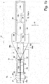
- FIGS. 1a . b . c the supply chain unit 44 is shown with a subsequent tubular bag assembly 1 :
- the supply chain 2 runs in a vertically standing circulating plane 2 ', which the drawing plane of FIG. 3a is, between a downstream pulley 2 a and an upstream pulley 2 b, of which at least one is driven to set the supply chain in the desired manner in motion.
- the driver 3 which are attached to the supply chain 2 , from the endless circulating supply chain 2 to the outside, thus protrude from the upper run of the feed chain 2 upwards and extend through a slot in the support surface for the products 100 on this support surface out to push the products lying on it 100 or product groups 100 ' on the support surface, which is in the form of support parts 15 a, b according to the supervision of FIG. 1b on both sides of the slot 25 extends for the driver 3 , slightly above the supply chain . 2
- the drivers 3 are widened in the rule and protrude laterally beyond the width of the slot 25 in order to push the products reliably forward, wherein on the support members 15 a, b also in the longitudinal direction 10 extending side guides 26 are arranged whose mutual distance is adapted as accurately as possible to the width of the products 100 , as well as the width - measured in the transverse direction 11 - the driver 3 is adapted to the width of the products 100 .
- FIG. 1a shows - and later on the basis of FIGS. 2a .
- b is explained in more detail - is the driver 3 the same Aufrechtwinkel 28, which he has taken during the main part of the conveyor line 23 to the horizontal plane, while diving around the pulley 2 a down around maintained until it is still in contact with the product 100 , Thus, until the upper edge of the contact surface 43 of the driver 3 is submerged below the level of the bearing surface for the products to avoid damaging the product.
- FIG. 1b shows in plan view, pushes the subducting down follower 3 at the end of the conveying path 27 of the supply chain unit 44, the product 100 to a storage surface 29, which is fixedly mounted in the following tubular bag assembly and downstream of the supporting parts 15 a , b, preferably at the same level or slightly lower.
- FIGS. 2a . b and 3a-d show the design and function of the supply chain 2, to which the drivers 3 are attached.
- FIG. 2a shows a part of the supply chain unit 44, namely the end of the conveying path 27 of the endless circulating supply chain 2 with a view of the orbital plane 2 ' .
- the supply chain 2 - with this term should include all suitable conveying elements - is formed in this case as a toothed belt and the horizontally running upper strand 2.1 is deflected at the end of the conveying path 27 via a first guide roller 2 a in this case at right angles downwards and over an approximately further arranged further deflection roller 2 b in turn to return horizontally lower strand 2 '.
- the drivers 3 protrude in the orbital plane 2 ' from the supply chain 2 to the outside, and along the upper run 2' in this case vertically upwards.
- FIG. 1b visible slot 25, which is formed in the longitudinal direction 10 b extending between the laterally disposed therefrom support members 15 a, b, over the top of the support surfaces 15 a, b out and thereby can in the area above in the transverse direction 11 over the slot 25 away Push the support parts 15 a, b lying forward product, in this case to the left.
- these drivers 3 are guided around the pulley 2 a at the end of the upper strand 2.1 in the direction 10 b, they would perform immovable attachment to the timing belt 2 with its forwardly directed contact surface 43 pivotal movement about the center of the guide roller 2 a, and so that the contact surface 43 in this area increasingly press with its upper edge against the back of the product 1 , and scraping down along this, which can damage the products 100 .
- the driver 3 are first of all formed on the supply chain 2 articulated about a pivot axis 7 extending in the transverse direction 11 .
- the driver 3 are formed in two parts with a base part 3 a, which is attached via the pivot axis 7 to the supply chain 2 and the driver part 3 b, which is wholly or predominantly above the support members 15 a, b and the base part 3 a is releasably attached.
- the driver part 3 b from above into the upper end face of the base part 3a can be inserted and latched - as in FIG. 2b shown in a separate state - by the driver part 3 b has on its underside an insertion pin 6 , which fits into a corresponding recess of the base part 3 a, and between both a detent device 36 is present, for example, a known, biased by spring force detent ball, the either in the base part 3 a or 3 b in the cam member may be provided and is biased in a corresponding catch recess in the other part by means of spring force and locks into place.
- the base part 3 a is in the direction of the FIG. 2a and 2 B , So in side view of the orbital plane 2 'of the supply chain 2, the transverse direction 11, L-shaped with an upwardly, ie with respect to the circulating supply chain 2 to the outside, facing Einsteckschenkel 3 a 2 , in which the receiving and locking device located for the driver part, and a thereto - preferably at the lower end - at an angle approximately in the direction of the supply chain 2 counter to the direction of travel 10 b extending guide leg 3 a first
- the driver 3, here the base part 3 a, may be arranged in a recess of the supply chain 2 , but is preferably viewed in the plan view of the side attached to this, as the supervision of Figure 2c shows.
- a slide guide 40 is arranged, the top and towards the end of the conveyor line an end face in the form of a guide curve 41, from the top to the front end of the bottom in the form of an arc is convexly curved, arranged so that at the beginning of running around the pivot axis 7 of a driver 3 to this guide roller 2 a, first the lower edge and then the rear, preferably rounded, free end of the guide leg 3 a 1 is guided by the guide cam 41 so that the driver 3 maintains its angular position with respect to the pivot axis 7 - and thus the upright angle 28 is also maintained - to the top of the driver 3, here so the driver part 3 b, under the Level of the top of the support members 15 a, b is submerged and loses contact with the previously pushed down her product 100 .
- FIG. 2a shows, the support parts 15 a, b ends before the end of the conveyor line 27 in the transport direction 10 b to the driver part 3 b of the driver 3, which according to FIG. 5b As a rule, wider than the slot 25, in which the driver 3 runs, can dive down.
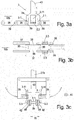
- FIGS. 3a -d show a normal link chain as a feed chain 2 and another way of mounting dogs 3 on such a link chain:
- a link chain consists of longitudinally spaced 10 , transversely extending, cylindrical chain webs 39, at the left and right end in each case an outer and an inner chain cheek 38 attack, the inner or the outer, usually the outer, chain cheek 38 pivotable about the transverse axis of the chain web 39 is.
- Each chain cheek 38 connects two such chain webs 39.
- Two middle, elastic latching arms 3.11 protrude in the middle of the longitudinal distance between the support arms 3.1 also from the central body down, spaced transversely about the width of a chain link 37.
- the locking arms 3.11 each have an inwardly directed cross -Rastnase 3.3 , which is directed towards the opposite transverse locking lug 3.3 and fits into a preferably formed in the outer chain cheek 38 formed detent opening and on the basis of the elastic bias of the locking arms 3.11 in this, wherein thereby the locking arms 3.11 laterally extend downwardly along the outer chain cheeks 38 .
- the contact surfaces of the contact arms 3.1 sit in this latched state on the two adjacent chain webs 39 .
- the contact surface 43 pointing in the running direction 10 b is curved backwards to avoid damaging the rear side of the product during the immersion under the contact surface.
- Figure 3c is also shown as a with such locking arms, in this case the elastic locking arms 3.11, equipped driver 3 by a driver tool 21 b, which may be attached to a robot arm on the tool hand 20 d, not only held, but the locking arms 3.11 so far together can be pressed against each other that the Driver 3 between the chain cheeks 38 retracted from above and when releasing the pressing against each other outwards into the locking opening 42 engages.
- driver tool 21 b two on both sides of the driver downwardly projecting, with the angled and with the free end inwardly against the locking arms 3.11 directed gripper 35 have to longitudinally 10 extending joints controlled relative to the main part of the driver -Tool 21 b can be pivoted to grasp or release the driver 3 to the locking arms 3.11.
- the base parts 3 a usually in a significantly larger distance at the feed chain 2, in particular a toothed belt, provided to keep the production expense over the respectively required articulated connection about the pivot axis 7 of such a toothed belt low, at a Link chain - except for the presence of the locking openings 42 - requires no additional work.
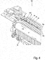
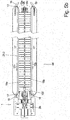
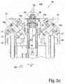
- FIGS. 4 and 5a - c show in an enlarged representation the supply chain unit 44 in whole or over only part of their conveying path 27 through which products, here a product group 100 'to be conveyed in the direction of the tubular bag assembly 1, where it is revolving Pad Parts 15 a, b on both sides of the slot 25, through which the driver 3 project from the supply chain 2 below in the area above the support parts 15 a, b are formed.
- the support parts 15 a, b are divided in the direction 10 in individual support sections 16, all of which are each attached to an endlessly circulating support chain 17 , of which one left and one right of the supply chain 2 is arranged, and each in a circulating plane 17 ' circulate in the FIGS. 5a , b drawn on the cover, which covers the circulation chain 17 .
- FIG. 5b and 5c for a relatively small product group 100 ' reveals, lies the product group 100' with its back to the driver 3 , which pushes them forward and lies with its bottom on both sides of the support members 15 a, b, so each one or more adjoining support -Sections 16, as in FIG. 5b and 5c recognizable, up.
- the circulating chain 17 is moved at the same speed in the direction 10 b as the supply chain 2 to relative movements between the bottom of the product or here the product group 100 and the top of the support parts 15 a, b, so the support portions 16 to avoid.
- FIG. 5c viewed in the longitudinal direction 10 b: It can be seen that the circumferential planes 17 'of the arranged on both sides of the supply chain 2 circulating chains 17 at an acute angle to the orbital plane 2' of the supply chain 2, symmetrical to the orbital plane 2 'of the supply chain 2, which simultaneously the longitudinal center plane 10' the entire conveyor line is arranged.
- the support portions 16 arranged on these feed chains 17 when moved synchronously with the drivers 3 with the aid of the upper run of the feed chain 17 , have a horizontal support surface, ie upper surface, the support portions 16 protrude from the circulation chain 17 and its orbital plane 17 ' in one corresponding angle.
Landscapes
- Engineering & Computer Science (AREA)
- Mechanical Engineering (AREA)
Claims (14)
- Unité de chaîne d'approvisionnement (44) avec- une surface d'appui (15) s'étendant dans un sens longitudinal (10b) pour les produits à approvisionner (100),- une chaîne d'approvisionnement sans fin (2) se déplaçant dans le sens longitudinal (10b) avec des entraîneurs (3) disposés à la chaîne dans des intervalles longitudinaux (9) pour avancer les produits (100) sur une distance de transport (27) le long de la surface d'appui (15),- où les entraîneurs (3) en une ou plusieurs pièces sont attachés directement ou indirectement de manière facilement amovible au moins en partie par rapport à la chaîne d'approvisionnement (2) de sorte qu'ils peuvent au moins en partie être démontés de la chaîne d'approvisionnement (2) montée dans une machine sans démonter la surface d'appui (15) et qu'ils peuvent également être attachés à des positions longitudinales différentes à la chaîne d'approvisionnement (2), caractérisé en ce que- un guide de coulisse fixe (40) est prévu pour les entraîneurs (3) de sorte que lors de la descente de l'entraîneur (3) ramené le long d'un brin supérieur (2.1) de la chaîne d'approvisionnement (2) dans la région d'action d'une poulie de renvoi en aval (2a), la surface de contact orientée en avant (43) de l'entraîneur (3) maintient au moins pendant une première partie de son cours autour de ladite poulie de renvoi (2a) son angle droit (28) initial par rapport à la direction horizontale, vu perpendiculaire au plan de circulation (2').
- Unité de chaîne d'approvisionnement selon la revendication 1,
caractérisé en ce que- la chaîne d'approvisionnement (2) s'étend sans fin, en particulier dans un plan de circulation vertical (2') qui est parallèle au sens longitudinal (10b) et passe autour d'au moins deux poulies de renvoi (2a, b) et- en particulier les entraîneurs (3) projettent de la chaîne d'approvisionnement (2) vers l'extérieure dans son plan de circulation (2'). - Unité de chaîne d'approvisionnement selon une des revendications précédentes,
caractérisé en ce que
les entraîneurs (3) sont attachés directement ou indirectement de manière facilement amovible au moins en partie par rapport à la chaîne d'approvisionnement (2) de sorte que pour la libération d'au moins une partie de chaque entraîneur (3) de la chaîne d'approvisionnement (2), il est ni nécessaire d'enlever la chaîne d'approvisionnement (2) de la machine où elle est montée ni de démonter aucun autre composant de la machine. - Unité de chaîne d'approvisionnement selon une des revendications précédentes, caractérisé en ce que- les entraîneurs (3) comprennent une partie de base (3a) montée de manière fixe à la chaîne d'approvisionnement (2) qui reste fixe également lors d'un changement de format et comprennent une partie d'entraîneur (3b) qui peut être fixé, en particulier encliqueté, à la partie de base (3a), et qui peut être échangé lors du changement de formatet en particulier- la partie d'entraîneur (3b) peut être introduite dans la partie de base (3a), en particulier dans sa face frontale libre dirigée dans la direction opposé à la chaîne d'approvisionnement (2), au moyen de tenons d'enfichage (6) arrangés à une des deux parts et d'une encoche correspondante a l'autre part, avec un dispositif d'arrêt (36) entre les deux, en particulier avec une bille d'encliquetage précontrainte par la force d'un ressort.
- Unité de chaîne d'approvisionnement selon une des revendications précédentes,
caractérisé en ce que- les entraîneurs (3) sont attachés directement et facilement amovible a des encoches de la chaîne d'approvisionnement (2) espacées dans le sens longitudinal (10 b), et sont en particulier intercalés et/ou encliquetés, et- en particulier les entraîneurs (3) comprennent une partie d'entraîneur (3b) qui est liée à une partie de base (3a) de manière pivotable mais non pas amovible autour d'un axe transversale et en ce que la partie de base (3a) est attachée de manière directement amovible et facilement amovible à la chaîne d'approvisionnement (2). - Unité de chaîne d'approvisionnement selon une des revendications précédentes,
caractérisé en ce que
la chaîne d'approvisionnement (2) comprend des membres de chaîne individuels reliés de manière articulée et en ce que les entraîneurs (3) sont attachée de manière directement et facilement amovible aux membres de chaîne (37) fonctionnant comme des encoches et sont en particulier intercalés et/ou encliquetés. - Unité de chaîne d'approvisionnement selon une des revendications précédentes,
caractérisé en ce que- l'entraîneur (3) ou sa partie de base (3a) comprend sur son côté face à la chaîne d'approvisionnement (2) d'un côté des surfaces d'appui pour un appui à la chaîne d'approvisionnement (2) et de l'autre côté des ergots d'encliquetage, en particulier des ergots d'encliquetage transversaux (3.3) encliquetant dans un sens transversal (11), pour encliqueter à des contre-membres respectifs de la chaîne d'approvisionnement (2), en particulier d'une chaîne articulée et en particulier- les ergots d'encliquetage, en particulier les ergots d'encliquetage transversaux (3.3), sont prévus à l'extrémité libre de bras d'encliquetage (3.11) orientés vers la chaîne d'approvisionnement (2). - Unité de chaîne d'approvisionnement selon une des revendications précédentes,
caractérisé en ce que
les côtés de chaîne (38) d'une chaîne articulée prévoient des ouvertures d'encliquetage, ouvertes de préférence du côté extérieur, qui reçoivent les ergots d'encliquetage, en particulier les ergots d'encliquetage transversaux (3.3), et en ce que dans cet état d'encliquetage les surfaces d'appui de l'entraîneur (3) ou de sa partie de base (3a) sont en appui à la chaîne d'approvisionnement (2), en particulier aux barres de chaîne (39) d'une chaîne articulée. - Unité de chaîne d'approvisionnement selon une des revendications précédentes, caractérisé en ce que- ou l'entraîneur complet (3), ou- dans le cas d'un entraîneur (3) avec plusieurs parties- sa partie de base (3a) à la chaîne d'approvisionnement (2)- ou sa partie d'entraîneur (3b) à la partie de base (3a)est attaché autour d'un axe de pivotement (7) orienté transversalement au sens de mouvement (1b) de la chaîne d'approvisionnement (2).
- Unité de chaîne d'approvisionnement selon une des revendications précédentes, caractérisé en ce que
le guide de coulisse (40) est adapté et positionné de sorte que la surface d'appui (43) maintient essentiellement son angle droit (28) jusqu'à ce que le bord supérieur de l'entraîneur (3) soit arrivé en dessous de la surface supérieur de la surface d'appui (15). - Unité de chaîne d'approvisionnement selon une des revendications précédentes, caractérisé en ce que
l'entraîneur (3) est adapté en forme de L avec un bras d'insertion (3a2) orienté vers l'extérieur par rapport au plan de circulation (2') et un bras de guidage (3a1) s'étendant de préférence à son extrémité inférieur de manière angulaire et par exemple contre le sens de circulation (10 b) de la chaîne d'approvisionnement (2). - Unité de chaîne d'approvisionnement selon une des revendications précédentes, caractérisé en ce que
le guide de coulisse (40) prévoit une courbe de guidage (41) s'étendant en appui contre le côté inférieur du bras de guidage (3a1) dans le sens de circulation (10b) et transversalement au plan de circulation (2') et s'étend à son extrémité dans le sens de circulation de la chaîne d'approvisionnement (2) dans une courbe convexe, en particulier en arc, dans l'espace intérieur de la chaîne d'approvisionnement (2) sans fin de sorte qu'en particulier pendant le pivotement de l'axe de pivotement (7) autour de la poulie de renvoi en aval (2a), le bras de guidage avec son extrémité libre orienté vers l'arrière arrive en appui contre la courbe convexe du groupe de guidage (41). - Unité de chaîne d'approvisionnement selon une des revendications précédentes, caractérisé en ce que
la surface d'appui (15)- comprend ou deux parties d'appui en alignement (15a, b), se terminant dans le sens longitudinal (10b) avant la fin de la distance de transport (27) de la chaîne d'approvisionnement (2) et avec une fente (25) entre celles-ci s'étendant dans le sens longitudinal (10b) à travers laquelle s'étendent les entraîneurs (3)- ou la surface d'appui (15) fait partie des entraîneurs (3). - Unité de chaîne d'approvisionnement selon une des revendications précédentes, caractérisé en ce que- la surface d'appui, pour les produits (100) circule avec la chaîne d'approvisionnement (2) sur les deux côtés de l'entraîneur (3), en particulier de manière synchrone, et les parties d'appui (15a, b) de la surface d'appui comprennent des deux côtés des entraîneurs (3) dans le sens de circulation (10b) des sections d'appui (16) successives dans le sens de circulation (10b), qui sont attachées, en particulier individuellement, en particulier à une chaîne d'appui sans fin (17),et en particulier- le plan de circulation (17') de la chaîne d'appui (17) vu dans le sens de circulation (10b) est arrangé dans un angle (18) et s'abaissant symétriquement des deux côtés par rapport au plan de circulation (2') généralement vertical de la chaîne d'approvisionnement (2).
Applications Claiming Priority (1)
| Application Number | Priority Date | Filing Date | Title |
|---|---|---|---|
| DE201520100657 DE202015100657U1 (de) | 2015-02-11 | 2015-02-11 | Zufuhrketten-Einheit |
Publications (2)
| Publication Number | Publication Date |
|---|---|
| EP3056455A1 EP3056455A1 (fr) | 2016-08-17 |
| EP3056455B1 true EP3056455B1 (fr) | 2018-11-28 |
Family
ID=52673708
Family Applications (1)
| Application Number | Title | Priority Date | Filing Date |
|---|---|---|---|
| EP16155267.4A Active EP3056455B1 (fr) | 2015-02-11 | 2016-02-11 | Unite de chaines d'approvisionnement |
Country Status (2)
| Country | Link |
|---|---|
| EP (1) | EP3056455B1 (fr) |
| DE (1) | DE202015100657U1 (fr) |
Families Citing this family (3)
| Publication number | Priority date | Publication date | Assignee | Title |
|---|---|---|---|---|
| CN108033051B (zh) * | 2017-12-22 | 2024-05-17 | 登封市启明轩程控设备有限公司 | 一种面条包装线及其面条输送装置、推送件 |
| CN113247682A (zh) * | 2021-05-21 | 2021-08-13 | 许昌裕同印刷包装有限公司 | 一种防刮伤推板装置、推料机及码垛机 |
| EP4108600A1 (fr) * | 2021-06-25 | 2022-12-28 | MULTIVAC Sepp Haggenmüller SE & Co. KG | Machine d'emballage dotée d'un convoyeur à barre de poussée |
Citations (1)
| Publication number | Priority date | Publication date | Assignee | Title |
|---|---|---|---|---|
| US20070056833A1 (en) * | 2005-09-15 | 2007-03-15 | Cash John W Iii | Carrier chain with an improved link |
Family Cites Families (5)
| Publication number | Priority date | Publication date | Assignee | Title |
|---|---|---|---|---|
| GB1449904A (en) * | 1973-10-01 | 1976-09-15 | Baker Perkins Holdings Ltd | Wrapping machines |
| NL9200915A (nl) * | 1992-05-22 | 1993-12-16 | Hadewe Bv | Riemsamenstel. |
| US6471041B1 (en) * | 2000-03-31 | 2002-10-29 | Kimberly-Clark Worldwide, Inc. | Roller chain attachment member |
| GB2436550A (en) * | 2006-03-31 | 2007-10-03 | Meadwestvaco Packaging Systems | Releasably engaging lugs and means of positioning the lugs |
| JP5870331B2 (ja) * | 2012-01-25 | 2016-02-24 | 旭精工株式会社 | 物搬送ベルト及び硬貨選別装置 |
-
2015
- 2015-02-11 DE DE201520100657 patent/DE202015100657U1/de not_active Expired - Lifetime
-
2016
- 2016-02-11 EP EP16155267.4A patent/EP3056455B1/fr active Active
Patent Citations (1)
| Publication number | Priority date | Publication date | Assignee | Title |
|---|---|---|---|---|
| US20070056833A1 (en) * | 2005-09-15 | 2007-03-15 | Cash John W Iii | Carrier chain with an improved link |
Also Published As
| Publication number | Publication date |
|---|---|
| EP3056455A1 (fr) | 2016-08-17 |
| DE202015100657U1 (de) | 2015-02-23 |
Similar Documents
| Publication | Publication Date | Title |
|---|---|---|
| DE60118948T2 (de) | Überführung von gegenständen zwischen entgegengesetzt angetriebenen förderern | |
| DE102005026639B4 (de) | Vorrichtung zum Aufteilen, Eintakten und Gruppieren von Stückgütern | |
| DE4438207C2 (de) | Übergabevorrichtung für auf einem umlaufenden endlosen Zuführband in Querreihen ankommenden Gegenstände | |
| EP3366614B1 (fr) | Unité de chaînes d'alimentation | |
| EP3056441B1 (fr) | Machine a sacs tubulaires et son procede de fonctionnement | |
| DE3527741A1 (de) | Vorrichtung zum foerdern von zigaretten-gruppen | |
| DE3209595A1 (de) | Maschine zum abfuellen und verpacken von nahrungsmitteln | |
| EP3056455B1 (fr) | Unite de chaines d'approvisionnement | |
| DE3029508C2 (de) | Vorrichtung zum Gruppieren von Werkstücken | |
| EP0283670B1 (fr) | Dispositif de groupement pour la formation de groupes de récipients | |
| DE7738506U1 (de) | Transporteinrichtung, insbesondere fuer die schrittweise befoerderung von werkstuecken bei pressen | |
| EP2478782B1 (fr) | Dispositif de transport pour produits en forme de tige de l'industrie de traitement du tabac | |
| DE2402972A1 (de) | Vorrichtung zur verteilung von gegenstaenden auf zwei foerderbahnen | |
| DE102015101930B3 (de) | Schlauchbeutelmaschine und Verfahren zu ihrem Betrieb | |
| DE69617534T2 (de) | Vorrichtung zum Überführen von Gegenständen | |
| DE69501290T2 (de) | Vorrichtung zum Verpacken von zerbrechlichen, zylindrischen Gegenständen, insbesondere von Zigaretten | |
| DE20200794U1 (de) | Vorrichtung zum Verteilen von Behältern | |
| DE602004008800T2 (de) | Vorrichtung und verfahren zum drehen von behältern | |
| DE2450934B2 (de) | Übergabevorrichtung zum gleichzeitigen Übergeben von Artikeln | |
| DE19958019C2 (de) | Verfahren und Vorrichtung zum kontrollierten Übernehmen eines Gegenstandes, insbesondere einer teilweise oder vollständig gebildeten Faltschachtel | |
| DE10051790A1 (de) | Behälter, Vorrichtung und Verfahren zum Transportieren von stabförmigen Artikeln der tabakverarbeitenden Industrie | |
| DE3011875C2 (de) | Rollenfördereinrichtung mit veränderbarer Förderbreite | |
| DE3030757A1 (de) | Automatische maschine zur bildung von teigringen aus lebensmittelteig | |
| DE19525436C2 (de) | Beschickung eines wenigstens in einem Abschnitt permanent laufenden Fördermittels | |
| DE2755190A1 (de) | Transportvorrichtung zum zufuehren von gegenstaenden zu mehreren arbeitsstationen |
Legal Events
| Date | Code | Title | Description |
|---|---|---|---|
| PUAI | Public reference made under article 153(3) epc to a published international application that has entered the european phase |
Free format text: ORIGINAL CODE: 0009012 |
|
| AK | Designated contracting states |
Kind code of ref document: A1 Designated state(s): AL AT BE BG CH CY CZ DE DK EE ES FI FR GB GR HR HU IE IS IT LI LT LU LV MC MK MT NL NO PL PT RO RS SE SI SK SM TR |
|
| AX | Request for extension of the european patent |
Extension state: BA ME |
|
| STAA | Information on the status of an ep patent application or granted ep patent |
Free format text: STATUS: REQUEST FOR EXAMINATION WAS MADE |
|
| 17P | Request for examination filed |
Effective date: 20170214 |
|
| RBV | Designated contracting states (corrected) |
Designated state(s): AL AT BE BG CH CY CZ DE DK EE ES FI FR GB GR HR HU IE IS IT LI LT LU LV MC MK MT NL NO PL PT RO RS SE SI SK SM TR |
|
| REG | Reference to a national code |
Ref country code: DE Ref legal event code: R079 Ref document number: 502016002598 Country of ref document: DE Free format text: PREVIOUS MAIN CLASS: B65G0019240000 Ipc: B65B0051300000 |
|
| RIC1 | Information provided on ipc code assigned before grant |
Ipc: B65B 59/00 20060101ALI20170814BHEP Ipc: B65B 9/06 20120101ALI20170814BHEP Ipc: B65B 35/44 20060101ALI20170814BHEP Ipc: B65B 35/24 20060101ALI20170814BHEP Ipc: B65B 51/30 20060101AFI20170814BHEP Ipc: B65G 19/24 20060101ALI20170814BHEP |
|
| STAA | Information on the status of an ep patent application or granted ep patent |
Free format text: STATUS: EXAMINATION IS IN PROGRESS |
|
| 17Q | First examination report despatched |
Effective date: 20171027 |
|
| GRAP | Despatch of communication of intention to grant a patent |
Free format text: ORIGINAL CODE: EPIDOSNIGR1 |
|
| STAA | Information on the status of an ep patent application or granted ep patent |
Free format text: STATUS: GRANT OF PATENT IS INTENDED |
|
| INTG | Intention to grant announced |
Effective date: 20180629 |
|
| GRAS | Grant fee paid |
Free format text: ORIGINAL CODE: EPIDOSNIGR3 |
|
| GRAA | (expected) grant |
Free format text: ORIGINAL CODE: 0009210 |
|
| STAA | Information on the status of an ep patent application or granted ep patent |
Free format text: STATUS: THE PATENT HAS BEEN GRANTED |
|
| AK | Designated contracting states |
Kind code of ref document: B1 Designated state(s): AL AT BE BG CH CY CZ DE DK EE ES FI FR GB GR HR HU IE IS IT LI LT LU LV MC MK MT NL NO PL PT RO RS SE SI SK SM TR |
|
| REG | Reference to a national code |
Ref country code: CH Ref legal event code: EP |
|
| REG | Reference to a national code |
Ref country code: AT Ref legal event code: REF Ref document number: 1069950 Country of ref document: AT Kind code of ref document: T Effective date: 20181215 |
|
| REG | Reference to a national code |
Ref country code: DE Ref legal event code: R096 Ref document number: 502016002598 Country of ref document: DE |
|
| REG | Reference to a national code |
Ref country code: IE Ref legal event code: FG4D Free format text: LANGUAGE OF EP DOCUMENT: GERMAN |
|
| REG | Reference to a national code |
Ref country code: CH Ref legal event code: NV Representative=s name: SCHMAUDER AND PARTNER AG PATENT- UND MARKENANW, CH |
|
| REG | Reference to a national code |
Ref country code: NL Ref legal event code: MP Effective date: 20181128 |
|
| REG | Reference to a national code |
Ref country code: LT Ref legal event code: MG4D |
|
| PG25 | Lapsed in a contracting state [announced via postgrant information from national office to epo] |
Ref country code: ES Free format text: LAPSE BECAUSE OF FAILURE TO SUBMIT A TRANSLATION OF THE DESCRIPTION OR TO PAY THE FEE WITHIN THE PRESCRIBED TIME-LIMIT Effective date: 20181128 Ref country code: IS Free format text: LAPSE BECAUSE OF FAILURE TO SUBMIT A TRANSLATION OF THE DESCRIPTION OR TO PAY THE FEE WITHIN THE PRESCRIBED TIME-LIMIT Effective date: 20190328 Ref country code: BG Free format text: LAPSE BECAUSE OF FAILURE TO SUBMIT A TRANSLATION OF THE DESCRIPTION OR TO PAY THE FEE WITHIN THE PRESCRIBED TIME-LIMIT Effective date: 20190228 Ref country code: NO Free format text: LAPSE BECAUSE OF FAILURE TO SUBMIT A TRANSLATION OF THE DESCRIPTION OR TO PAY THE FEE WITHIN THE PRESCRIBED TIME-LIMIT Effective date: 20190228 Ref country code: FI Free format text: LAPSE BECAUSE OF FAILURE TO SUBMIT A TRANSLATION OF THE DESCRIPTION OR TO PAY THE FEE WITHIN THE PRESCRIBED TIME-LIMIT Effective date: 20181128 Ref country code: LT Free format text: LAPSE BECAUSE OF FAILURE TO SUBMIT A TRANSLATION OF THE DESCRIPTION OR TO PAY THE FEE WITHIN THE PRESCRIBED TIME-LIMIT Effective date: 20181128 Ref country code: LV Free format text: LAPSE BECAUSE OF FAILURE TO SUBMIT A TRANSLATION OF THE DESCRIPTION OR TO PAY THE FEE WITHIN THE PRESCRIBED TIME-LIMIT Effective date: 20181128 Ref country code: HR Free format text: LAPSE BECAUSE OF FAILURE TO SUBMIT A TRANSLATION OF THE DESCRIPTION OR TO PAY THE FEE WITHIN THE PRESCRIBED TIME-LIMIT Effective date: 20181128 |
|
| PG25 | Lapsed in a contracting state [announced via postgrant information from national office to epo] |
Ref country code: SE Free format text: LAPSE BECAUSE OF FAILURE TO SUBMIT A TRANSLATION OF THE DESCRIPTION OR TO PAY THE FEE WITHIN THE PRESCRIBED TIME-LIMIT Effective date: 20181128 Ref country code: RS Free format text: LAPSE BECAUSE OF FAILURE TO SUBMIT A TRANSLATION OF THE DESCRIPTION OR TO PAY THE FEE WITHIN THE PRESCRIBED TIME-LIMIT Effective date: 20181128 Ref country code: AL Free format text: LAPSE BECAUSE OF FAILURE TO SUBMIT A TRANSLATION OF THE DESCRIPTION OR TO PAY THE FEE WITHIN THE PRESCRIBED TIME-LIMIT Effective date: 20181128 Ref country code: GR Free format text: LAPSE BECAUSE OF FAILURE TO SUBMIT A TRANSLATION OF THE DESCRIPTION OR TO PAY THE FEE WITHIN THE PRESCRIBED TIME-LIMIT Effective date: 20190301 Ref country code: PT Free format text: LAPSE BECAUSE OF FAILURE TO SUBMIT A TRANSLATION OF THE DESCRIPTION OR TO PAY THE FEE WITHIN THE PRESCRIBED TIME-LIMIT Effective date: 20190328 |
|
| PG25 | Lapsed in a contracting state [announced via postgrant information from national office to epo] |
Ref country code: NL Free format text: LAPSE BECAUSE OF FAILURE TO SUBMIT A TRANSLATION OF THE DESCRIPTION OR TO PAY THE FEE WITHIN THE PRESCRIBED TIME-LIMIT Effective date: 20181128 |
|
| PG25 | Lapsed in a contracting state [announced via postgrant information from national office to epo] |
Ref country code: PL Free format text: LAPSE BECAUSE OF FAILURE TO SUBMIT A TRANSLATION OF THE DESCRIPTION OR TO PAY THE FEE WITHIN THE PRESCRIBED TIME-LIMIT Effective date: 20181128 Ref country code: DK Free format text: LAPSE BECAUSE OF FAILURE TO SUBMIT A TRANSLATION OF THE DESCRIPTION OR TO PAY THE FEE WITHIN THE PRESCRIBED TIME-LIMIT Effective date: 20181128 Ref country code: CZ Free format text: LAPSE BECAUSE OF FAILURE TO SUBMIT A TRANSLATION OF THE DESCRIPTION OR TO PAY THE FEE WITHIN THE PRESCRIBED TIME-LIMIT Effective date: 20181128 |
|
| REG | Reference to a national code |
Ref country code: DE Ref legal event code: R097 Ref document number: 502016002598 Country of ref document: DE |
|
| PG25 | Lapsed in a contracting state [announced via postgrant information from national office to epo] |
Ref country code: SM Free format text: LAPSE BECAUSE OF FAILURE TO SUBMIT A TRANSLATION OF THE DESCRIPTION OR TO PAY THE FEE WITHIN THE PRESCRIBED TIME-LIMIT Effective date: 20181128 Ref country code: EE Free format text: LAPSE BECAUSE OF FAILURE TO SUBMIT A TRANSLATION OF THE DESCRIPTION OR TO PAY THE FEE WITHIN THE PRESCRIBED TIME-LIMIT Effective date: 20181128 Ref country code: RO Free format text: LAPSE BECAUSE OF FAILURE TO SUBMIT A TRANSLATION OF THE DESCRIPTION OR TO PAY THE FEE WITHIN THE PRESCRIBED TIME-LIMIT Effective date: 20181128 Ref country code: SK Free format text: LAPSE BECAUSE OF FAILURE TO SUBMIT A TRANSLATION OF THE DESCRIPTION OR TO PAY THE FEE WITHIN THE PRESCRIBED TIME-LIMIT Effective date: 20181128 |
|
| PLBE | No opposition filed within time limit |
Free format text: ORIGINAL CODE: 0009261 |
|
| STAA | Information on the status of an ep patent application or granted ep patent |
Free format text: STATUS: NO OPPOSITION FILED WITHIN TIME LIMIT |
|
| PG25 | Lapsed in a contracting state [announced via postgrant information from national office to epo] |
Ref country code: LU Free format text: LAPSE BECAUSE OF NON-PAYMENT OF DUE FEES Effective date: 20190211 Ref country code: MC Free format text: LAPSE BECAUSE OF FAILURE TO SUBMIT A TRANSLATION OF THE DESCRIPTION OR TO PAY THE FEE WITHIN THE PRESCRIBED TIME-LIMIT Effective date: 20181128 Ref country code: SI Free format text: LAPSE BECAUSE OF FAILURE TO SUBMIT A TRANSLATION OF THE DESCRIPTION OR TO PAY THE FEE WITHIN THE PRESCRIBED TIME-LIMIT Effective date: 20181128 |
|
| 26N | No opposition filed |
Effective date: 20190829 |
|
| REG | Reference to a national code |
Ref country code: BE Ref legal event code: MM Effective date: 20190228 |
|
| REG | Reference to a national code |
Ref country code: IE Ref legal event code: MM4A |
|
| PG25 | Lapsed in a contracting state [announced via postgrant information from national office to epo] |
Ref country code: IE Free format text: LAPSE BECAUSE OF NON-PAYMENT OF DUE FEES Effective date: 20190211 |
|
| PG25 | Lapsed in a contracting state [announced via postgrant information from national office to epo] |
Ref country code: BE Free format text: LAPSE BECAUSE OF NON-PAYMENT OF DUE FEES Effective date: 20190228 |
|
| PG25 | Lapsed in a contracting state [announced via postgrant information from national office to epo] |
Ref country code: TR Free format text: LAPSE BECAUSE OF FAILURE TO SUBMIT A TRANSLATION OF THE DESCRIPTION OR TO PAY THE FEE WITHIN THE PRESCRIBED TIME-LIMIT Effective date: 20181128 |
|
| PG25 | Lapsed in a contracting state [announced via postgrant information from national office to epo] |
Ref country code: MT Free format text: LAPSE BECAUSE OF FAILURE TO SUBMIT A TRANSLATION OF THE DESCRIPTION OR TO PAY THE FEE WITHIN THE PRESCRIBED TIME-LIMIT Effective date: 20181128 |
|
| GBPC | Gb: european patent ceased through non-payment of renewal fee |
Effective date: 20200211 |
|
| PG25 | Lapsed in a contracting state [announced via postgrant information from national office to epo] |
Ref country code: GB Free format text: LAPSE BECAUSE OF NON-PAYMENT OF DUE FEES Effective date: 20200211 |
|
| PG25 | Lapsed in a contracting state [announced via postgrant information from national office to epo] |
Ref country code: CY Free format text: LAPSE BECAUSE OF FAILURE TO SUBMIT A TRANSLATION OF THE DESCRIPTION OR TO PAY THE FEE WITHIN THE PRESCRIBED TIME-LIMIT Effective date: 20181128 |
|
| PG25 | Lapsed in a contracting state [announced via postgrant information from national office to epo] |
Ref country code: HU Free format text: LAPSE BECAUSE OF FAILURE TO SUBMIT A TRANSLATION OF THE DESCRIPTION OR TO PAY THE FEE WITHIN THE PRESCRIBED TIME-LIMIT; INVALID AB INITIO Effective date: 20160211 |
|
| REG | Reference to a national code |
Ref country code: AT Ref legal event code: MM01 Ref document number: 1069950 Country of ref document: AT Kind code of ref document: T Effective date: 20210211 |
|
| PG25 | Lapsed in a contracting state [announced via postgrant information from national office to epo] |
Ref country code: AT Free format text: LAPSE BECAUSE OF NON-PAYMENT OF DUE FEES Effective date: 20210211 |
|
| PG25 | Lapsed in a contracting state [announced via postgrant information from national office to epo] |
Ref country code: MK Free format text: LAPSE BECAUSE OF FAILURE TO SUBMIT A TRANSLATION OF THE DESCRIPTION OR TO PAY THE FEE WITHIN THE PRESCRIBED TIME-LIMIT Effective date: 20181128 |
|
| P01 | Opt-out of the competence of the unified patent court (upc) registered |
Effective date: 20230527 |
|
| REG | Reference to a national code |
Ref country code: CH Ref legal event code: U11 Free format text: ST27 STATUS EVENT CODE: U-0-0-U10-U11 (AS PROVIDED BY THE NATIONAL OFFICE) Effective date: 20260301 |
|
| PGFP | Annual fee paid to national office [announced via postgrant information from national office to epo] |
Ref country code: DE Payment date: 20260123 Year of fee payment: 11 |
|
| PGFP | Annual fee paid to national office [announced via postgrant information from national office to epo] |
Ref country code: IT Payment date: 20260224 Year of fee payment: 11 |
|
| PGFP | Annual fee paid to national office [announced via postgrant information from national office to epo] |
Ref country code: FR Payment date: 20260218 Year of fee payment: 11 |
|
| PGFP | Annual fee paid to national office [announced via postgrant information from national office to epo] |
Ref country code: CH Payment date: 20260301 Year of fee payment: 11 |