EP3056891A1 - Support d'echantillon de materiau comprenant une unite de commande - Google Patents
Support d'echantillon de materiau comprenant une unite de commande Download PDFInfo
- Publication number
- EP3056891A1 EP3056891A1 EP16153443.3A EP16153443A EP3056891A1 EP 3056891 A1 EP3056891 A1 EP 3056891A1 EP 16153443 A EP16153443 A EP 16153443A EP 3056891 A1 EP3056891 A1 EP 3056891A1
- Authority
- EP
- European Patent Office
- Prior art keywords
- pressure
- valve
- fluid
- actuator
- holder
- Prior art date
- Legal status (The legal status is an assumption and is not a legal conclusion. Google has not performed a legal analysis and makes no representation as to the accuracy of the status listed.)
- Granted
Links
Images


Classifications
-
- G—PHYSICS
- G01—MEASURING; TESTING
- G01N—INVESTIGATING OR ANALYSING MATERIALS BY DETERMINING THEIR CHEMICAL OR PHYSICAL PROPERTIES
- G01N3/00—Investigating strength properties of solid materials by application of mechanical stress
- G01N3/02—Details
-
- G—PHYSICS
- G01—MEASURING; TESTING
- G01N—INVESTIGATING OR ANALYSING MATERIALS BY DETERMINING THEIR CHEMICAL OR PHYSICAL PROPERTIES
- G01N3/00—Investigating strength properties of solid materials by application of mechanical stress
- G01N3/32—Investigating strength properties of solid materials by application of mechanical stress by applying repeated or pulsating forces
- G01N3/36—Investigating strength properties of solid materials by application of mechanical stress by applying repeated or pulsating forces generated by pneumatic or hydraulic means
-
- G—PHYSICS
- G01—MEASURING; TESTING
- G01N—INVESTIGATING OR ANALYSING MATERIALS BY DETERMINING THEIR CHEMICAL OR PHYSICAL PROPERTIES
- G01N2203/00—Investigating strength properties of solid materials by application of mechanical stress
- G01N2203/02—Details not specific for a particular testing method
- G01N2203/04—Chucks, fixtures, jaws, holders or anvils
- G01N2203/0411—Chucks, fixtures, jaws, holders or anvils using pneumatic or hydraulic pressure
-
- G—PHYSICS
- G01—MEASURING; TESTING
- G01N—INVESTIGATING OR ANALYSING MATERIALS BY DETERMINING THEIR CHEMICAL OR PHYSICAL PROPERTIES
- G01N3/00—Investigating strength properties of solid materials by application of mechanical stress
- G01N3/02—Details
- G01N3/04—Chucks
Definitions
- the present invention relates to a holder with a drive unit, in particular as part of a material testing machine for testing material samples, for. B. of metallic material samples.
- the drive unit operates with a pressurized fluid from a pressure source, for. B. a pump.
- the drive unit is configured according to the preamble of claim 1.
- the holder cooperates with a fluidic circuit of a materials testing machine.
- the invention equally relates to a material testing machine according to the preamble of claim 14, wherein a clamping force, for. B. for holding a sample of material, can be applied particularly secure.
- an associated method - according to the preamble of claim 15 - such a holder can be operated. By the method, an actuator can be brought into position, i. h., a closing operation and a clamping operation can be realized by the control.
- the holders are available in different embodiments. Centering tensioners or centering clamps which facilitate alignment of the sample in the direction of a desired test axis are particularly advantageous. Such centering can be z. B. in the EP 2 677 296 A2 (Applicant: Zwick GmbH & Co. KG, priority date: 22.06.2012). This type and similar types of holders are then installed in material testing machines, so that a material testing machine can take a test sample via appropriate holders.
- the materials testing machines are usually used to determine material properties used, in particular for material testing of metals.
- a test device is used, which serves to receive the material sample to be tested.
- the tester can be realized in a variety of ways. For example, test measurements with tensile forces can be carried out with so-called lever arm testing machines. In this case acts on the test sample a tensile force, which is translated by a lever arm. More about this type testing machine is in the patent DE 11 2009 005 323 B4 (Patent owner: Messphysik Materials Testing GmbH, filing date 17.10.2009). Another type tester describes the patent DE 11 2006 003 923 B4 (Patent owner: Shimadzu Corp., filing date: 12.06.2006).
- This type of material testing machine includes a pair of column members and a longitudinally extending support post.
- the test specimen in this type is attached to a mounting boss of an attachment unit, in other words, to a particular holder.
- the crossbeam is supported by the support post in material testing machines constructed in this way, thereby enabling material testing by sliding along the support post.
- a material testing machine with two sample receptacles, wherein a sample holder is firmly anchored in the base frame, is in the document DE 10 2009 036 247 A1 (Applicant: Zwick GmbH & Co. KG, filing date: 05.08.2009).
- This testing machine has two sample receptacles, in particular for testing in compression and tensile tests on springs and elastic components.
- a test receptacle is attached to a movable actuator.
- the material test is carried out by recording the measured data by means of a displacement transducer and a force transducer.
- a particularly advantageous pneumatic or hydraulic circuit in other words a fluidic circuit, can be the DE 10 2012 101 459 A1 (Applicant: Zwick GmbH & Co. KG, filing date: 23.02.2012) also as EP 2 631 496 A2 (Applicant: Zwick GmbH & Co. KG, priority date: 23.02.2012) published, refer.
- Such a circuit provides the desired level of security, but it takes a while until the actual test can take place, which u. a. from the jog mode.
- the clamping of each individual material sample constitutes an efficiency-limiting factor or a flow-limiting factor in such a circuit for the fluidic control of the clamping jaws.
- the test apparatus presented there utilizes a force shunt forming device.
- the force shunting device is intended to be capable of guiding a biasing force acting from a force application device to another force application device bridging the sample in the two sample restraining devices.
- the test procedure starts after the sample has been clamped on a still unloaded sample while the test machine is preloaded to a value.
- the CN 101 608 987 A1 (Applicant: Taiyuan Heavy Machinery Joint, priority date: 24.07.2009) describes another type of material testing device.
- the in the CN 101 608 987 A1 shown hydraulic circuit is to clamp a clamping device with piston, which can pinch an expandable tube. About distance sensors in Cylinders, the position of the piston is measured. Depending on the measuring signals, a relief valve can be actuated. During a pressure test on the pipe, the relief valve can be opened in the event of an overload in the hydraulic circuit. This is intended to protect the circuit.
- the CN 101 608 987 A1 discusses the issue of avoiding peak pressures in feedback generated by the specimen in the hydraulic circuit presented there.
- the patent DE 28 39 341 C3 (Owner: Daimler-Benz AG, Disclosure Date: 13.03.1980) relates to circuits with pneumatic flip-flops, with a flip-flop in a "high pressure range" of up to 8 bar to work.
- a flip-flop should always be in a stable state, regardless of whether or not a signal is present at its input.
- As a field of application of such a circuit is pointed to chucks, z. B. for tools that are clamped with a working cylinder.
- a safety device according to DE 2 158 700 A (Applicant: Festo-münfabrik Gott Kunststoff Gott Kunststoff, filing date: 26.11.1971) is to serve to control the flow of pressure medium to a consumer site, such as a press, punching or bending device.
- a consumer site such as a press, punching or bending device.
- the main control valve is operated to supply the consumer.
- the consumer unit is in FIG.
- FIG. 1 upstream of a so-called consumer valve, which is drawn cylinder-like with a spring on a side facing away from the main control valve of a piston.
- the FIG. 1 At least with respect to the presence of a pressure source is incomplete. As a reason for producing a higher level of security is explained for the arrangement of consumer valve, main valve and consumer point that so that the safety device can be driven with a low pressure. D. h., Priority is to reduce the pressure in the circuit, but clamping pressures are distinguished by exceptionally high pressures.
- a pneumatic or hydraulic clamping device for workpieces with movable and fixed clamping part is in DE 1 552 653 C (Patent proprietor: J. Gottling Peiseler, filing date: 09.02.1966) described, wherein the movable clamping part is driven with a cylinder-piston drive and a hand-operated control member is provided between the cylinder and a pressure medium source.
- the document mentions a force of up to 15 kp (about 150 Newtons) considered to be non-hazardous.
- the safety function is essentially realized via a plunger and a driver in the form of a set screw, which is set to a workpiece thickness.
- the adjusting screw not only serves to operate the plunger, but also as a stop to limit movement in conjunction with a counter-stop.
- the movement sequence during clamping should be such that the plunger only releases the full pressure or final pressure of the pressure source and the set screw on the counter stop surface limits a path that is covered under this high pressure.
- the high pressure can z. B. caused by a weight force in the order of 250 kp.
- a switching arm actuates a switch, whereby a valve in a bypass line is closed, so that the entire pressure of the pump is applied to the piston.
- the extension should be able to be interrupted if accidentally a hand or arm was placed between the moldings.
- the thrust force for a closing movement is to be achieved by passing pressure medium flowed into the rear side of a piston onto the front side, wherein a resistance of a compression spring is to be overcome.
- the sensor in a state after running on a hard material, causes the blocking of the air passage between the master cylinder chambers and a venting of the front cylinder chamber.
- the DE 101 61 703 B4 (Patent owner: FESTO AG & Co. KG, filing date: 15.12.2001) deals with a venting device for the controlled venting of a pneumatic drive.
- a venting device for the controlled venting of a pneumatic drive.
- the movement of a drive piston can be tapped with two working chambers for the operation of any components or devices.
- a shuttle valve is switched on, which controls the outflow of air from the two working chambers.
- the shuttle valve should close only those input whose associated working chamber is currently exposed to the fastest pressure drop. Due to the uniform venting of both working chambers, the pressures prevailing in it should always exert approximately equal pressure forces on the drive piston, so that this in the Standstill remains. This should be z. B. an emergency stop function an undesirable movement of a pneumatic drive can be prevented to prevent damage to man or machine.
- a circuit on the one hand should offer the highest possible degree of safety, on the other hand be suitable for a series test, in particular as part of a material testing machine. That is, such aspects as reduction of measurement errors, alignment times, and reproduction deviations and variations should be addressed by a corresponding holder, its material testing machine, and its operation.
- a speed of course also in a material test, can produce a considerable risk (cf the saying "speed kills").
- speed kills The question arises with which drive a material testing machine, more precisely its holder, has to be equipped, in which the material testing machine presents only the lowest possible probability of an accident by squeezing body parts before the actual material testing.
- a holder which can also be called a sample holder, in a material testing machine is intended to hold a material sample to be clamped, in particular to hold it reliably against a test force at a location. While performing a test, the material sample should not be able to come out of the holder. In addition, holders often even serve to introduce the test force onto the material sample. The forces are so considerable or high that the holder its holding and clamping force for the sample advantageously pneumatically, hydraulically or electrically, for. B. using linear motors, receives. Therefore, in such holders also includes a drive unit to the material testing machine, with the z. B. jaws, the jaws, moved and / or can be moved. Combinations of different types of movement and means are also possible, for. B.
- the holder is thus buildable in a material testing machine for material samples.
- the operation of a movable part such as a clamping jaw in the holder is possible by an actuator.
- a fluid such as compressed air or hydraulic medium, e.g. As a hydraulic medium hydraulic oil, receives its pressure from a pressure source.
- the material testing machine or the holder comprise a connection for one or even the pressure source itself. In the holder, therefore, at least one first actuator is present, which can be acted upon by a fluid from a pressure source.
- a tensioner with one or more small holding jaw (s), a tensioner with one or more middle holding jaw (s) or a tensioner with at least one large Holding jaw to use.
- Small clamping surfaces are in a range of about 30 mm X 30 mm.
- Large clamping jaws have holding surfaces of more than 100 mm X 100 mm.
- the holding surface in particular under the action of a higher force (in comparison with the force during the pure holding phase), to a clamping surface.
- the drive unit can be realized in one embodiment as a pneumatic or as a hydraulic circuit with corresponding valves. Between the pressure source and the actuator a bi-stable fluid control valve is provided as a possible valve.
- a fluid control valve should have at least a first and a second state. Other states may be provided in the fluid control valve. In the simplest embodiment of the circuit described in more detail below, it requires a component such as a bi-stable fluid control valve, which offers at least two states. In more complex embodiments, instead of the two-position fluid-free valve Also install a multi-position fluid control valve. Similarly, a counter operates, over which different states can be set.
- the actuator comprises at least one tensioning piston.
- the clamping piston can give a specific position.
- a second actuator is provided.
- the second actuator can also be referred to as a movement unit due to its motive force on the tensioning piston.
- a force is applied from a second actuator.
- the provided by the second actuator force is z. B. on a mechanical connection or via a fluid force transmission means on the clamping piston.
- the second actuator makes it possible to overcome by the force of at least one static friction of the clamping piston.
- the actuating force is advantageously at least greater than a frictional force of the clamping piston.
- the clamping piston of the holder is movable by the adjusting force, in particular unidirectional, on a travel. Due to the actuating force, the actuator, with no other existing pressures, assumes a closed position (whereby the naturally existing air pressure - for reasons of simplification - may first be neglected). When taking a closed position this is determined by the available travel.
- the travel of the tensioning piston can be completed by a physical obstacle, such as by a stop, in particular on a material sample.
- the additional actuator that is, in particular the second actuator or the additionally acting actuator, exerts a positioning force which, in particular for reasons of efficiency, should be directed predominantly in one direction.
- a closing pressure can be exerted on the piston.
- the clamping force or the pressure from which derives the clamping force of the jaw is also directed.
- the clamping force and the actuating force act in the same direction.
- clamping force and force should be of different sizes so that they can perform different tasks.
- the clamping force and the actuating force act via the piston on a sample to be inserted or inserted when the closed position is reached.
- clamping force and force are rectified to the piston.
- clamping force and force are superimposed.
- the second actuator acts in the same direction as the pressure-generating medium acts on the piston (means for the clamping pressure or for the clamping force).
- the bistable fluid control valve is temporarily in a first or in a second state.
- At least a first valve control line is present in the circuit.
- the fluid control valve is connected to the first valve control line.
- a fluid pressure in the first valve control line affects the state of the fluid control valve.
- a second valve control line which is also connected to the fluid control valve, supplies the fluid control valve with a second control pressure.
- the second control pressure may also affect the state of the fluid control valve.
- the first valve control line is connected to a chamber of the actuator.
- the chamber pressure of the actuator is applied to the fluid control valve via the first valve control line.
- the value of the threshold pressure is a pressure value by which decides whether a state change from the first state to the second state is performed. If the pressure in the first valve control line is below the threshold pressure, the unstable fluid control valve can change to the second state.
- a threshold pressure z a pressure in a pressure range of 0.8 to 1.1 bar, such as 1 bar (in a pneumatically operating valve), be provided for comparison with a supplied control pressure in the fluid control valve.
- a higher, set threshold pressure may be advantageous, for. B. depending on the working pressure range of a material testing machine.
- the threshold pressure z. B. 1 bar above the minimum working pressure of the working pressure range can be set as a reference.
- a higher threshold pressure than 1 bar can z. B. in a hydraulically operating drive unit, so be useful in a hydraulic fluid control valve.
- a change of state of the fluid control valve is ideally additionally dependent on a switching signal.
- the switching signal should be applied to the fluid control valve.
- the switching signal can be supplied to the fluid control valve via the second valve control line.
- the second state can only be taken if both the first valve control line and the second valve control line signal or admit the permissibility of the switching.
- the undershooting of the threshold pressure can be referred to as a first switching signal.
- a switching signal in the second valve control line can be referred to as a second switching signal.
- the second switching signal may, in one embodiment, be present at a time before the first switching signal.
- the change to the second state only occurs when the pressure from the chamber of the actuator causes the pressure in the first valve control line to drop below the threshold pressure.
- a safety check automatically takes place, which prevents a random change to the second state, possibly in a dangerous situation.
- the requirement of a switching signal, in particular a second switching signal, in the second valve control line makes it possible to bind the assumption of the second state to a, in particular the safety even further increasing, switching requirement mandatory. This switching requirement is preferably to be generated by an actuating person.
- the transition to the second state of the fluid control valve, with which an increase in the risk potential may be associated at least double secure. It is even possible to link the provision of the switching signal to the fulfillment of a plurality of security requirements as the first condition to be met, e.g. B. the operation of buttons, z. B. the observance of light barriers.
- the second switching signal is not present until the first switching signal has been previously generated; d. h., Inverse to the above procedure.
- the fluid-control valve only changes to the second state when, in a first valve control line, which can be supplied with pressure by a chamber of the actuator, i. h., Is supplied under normal circumstances, a threshold pressure is exceeded and in addition in the second valve control line, a switching signal applied to the fluid control valve. If the pressure in the first valve control line is above the threshold pressure, the second state can not be ingested.
- the security concept of the holder thus comprises an intrinsic part and an extrinsically modifiable part of the control unit, so that a faulty operation can be largely excluded.
- the second switching signal may be considered an extrinsic condition.
- the first condition, ie the intrinsic part depends - in one embodiment - on the pressure conditions in the circuit, in particular at one or more points in the circuit.
- the material testing machine in particular for testing metallic samples, comprises a holder for material samples. This is a pressurized fluid can be supplied. The fluid can impart a clamping force to the holder for a clamping state.
- the holder can z. B. comprise a first and a second tensioner, with the Werkstoffprobeend Schemee clamped are.
- Materials testing machines subject material samples at least one controlled, in some applications, a repeated load, such. B. a clamping force. Examples of material testing machines that require a particularly secure hold for a material sample, in particular due to sample loads to destruction or breakage, are tensile and / or pressure testing machines. In material testing machines, which are used in such a way that frequent sample changes are to be made, ie the sample changes are to be regarded as routine work, the danger of inattention increases when sample changes.
- the holder is intended for non-positive operation.
- the jaws are to hold the sample frictionally.
- the clamping or holding of the sample takes place by means of the clamping jaws in a non-positive manner. If a finger is located between the clamping jaws, it is often no longer possible to pull it out between the clamping jaws due to the clamping pressures.
- the holder has a position that can be referred to as an open position. In the open position z. B. the material sample from the holder removed.
- the holder has a position that can be referred to as the closed position.
- the holder is in the closed position, a clamping state is ingestible.
- the closed position of the holder may differ from a clamping position of the holder. Closed position and final clamping position can, but need not be the same location.
- the open position and the closed position of the holder can also be referred to as tension-free states of the holder.
- a movement of the holder, in particular of the tensioner, with respect to a material sample can be carried out by a movement unit.
- the movement unit is connected to the holder.
- the movement unit is preferably in a permanently active operating state, ie the movement unit is operated permanently, ie even when no movement takes place.
- the movement unit serves to assume a preferred position of the holder.
- the closed position can be such a preferred position.
- at least one first holding force is applied to the material sample.
- the first holding force can be provided by a second actuator and a second holding force by a fourth actuator.
- an actuator can generate the motion of a motion unit.
- the safety force vector provides the power to drive a jaw.
- a safety force vector is understood to mean a directed force whose magnitude preferably does not exceed 150 Newton (N).
- One Safety force vector or a closing pressure or a first clamping pressure can, for. B. be limited by means of a fixed spring constant or a pressure relief valve. Also, a closing pressure of 2 N / mm 2 can be considered safe if physical damage is to be avoided in view of a risk of injury. Due to the definition of a limit, the security is given both by a safety force vector and a closing pressure, so even when using a first and a second, z. B. for the first smaller, jaw size. A preference direction points from the open position to the closed position.
- a (defined) limit value of a clamping pressure or closing pressure can preferably be exceeded only in the closed position by means of a control unit.
- a method of control which offers special protection during handling, can be z. B. on holders for material samples or tools (material testing) use.
- the method can be implemented particularly advantageously with a drive unit set out above.
- the method uses or builds on the fact that at least one actuator and at least one bi-stable fluid control valve, shortened also referred to as a valve, are present.
- At least one, preferably two, connecting pressure medium lines are between actuator and valve.
- a pressure medium line also leads at least from the fluid control valve to a pressure source of a fluid.
- the fluid control valve can provide a connection to the pressure source at least in a switching state.
- the actuator can assume at least one position that is no longer the starting position.
- One of the actuator positions, z. B. the first position is a closed position.
- a second position can be present as a hold-open position or open position. Instead of a second position but also a range of motion can be provided. Outside the closed position of the actuator opens a receiving area, in particular for inserting a material sample or a tool in a holder.
- the actuator is kept open by a hold pressure.
- the hold-down pressure may be a pressure in the actuator itself.
- a safety closing force is applied, which precludes the Aufhaltetik.
- the safety closing force can be provided inside the actuator.
- the safety closing force or a part of the safety closing force can be supplied from outside the actuator.
- the hold-off position is exited when the hold-down pressure is too low to compensate for the safety-closing force.
- the stagnation pressure acts on the fluid control valve and sets a switching state of the valve, in particular a pressure-free state, such as a pressure source lock on the actuator fixed. A change of the switching state allows the Structure of a clamping pressure in the actuator.
- the clamping pressure acts in the actuator in a direction opposite to a direction of the hold-up pressure.
- the structure of the clamping pressure is carried out from the pressure source through the fluid control valve in the actuator when a sufficient degradation of the stagnation pressure has occurred.
- the stoppage pressure should have fallen so far that the safety closing force on the movement of the actuator.
- the stoppage pressure preferably follows a pressure-time characteristic.
- the hold-up pressure correlates with a movement of the actuator in the closed position.
- the stoppage pressure in the closed position can also be referred to as the closed position pressure of the actuator.
- the closed position pressure is an undershot threshold value of a fluid pressure which can be led out of the actuator via at least one pressure line. After a successful reduction of the stoppage pressure a change in state of the fluid control valve is possible.
- the hold-down pressure secures the fluid-free-valve against a change of state into a passage state for pressure from the pressure source.
- the passage state is ingestible when requested or subsequently requested, ie after the release pressure has been released.
- an input unit is provided.
- the input unit can be added to the drive unit, in which case the input unit is part of the drive unit.
- the input unit gives the request for a state change to the fluid control valve. In other words, when at least two, preferably three, switching conditions are met, the fluid control valve switches to a transmission state.
- the construction of a clamping pressure is secured at least twice against an untimely onset.
- a jaw should be able to take several, at least two end positions.
- One of the positions should be a closed position. Consequently, a holder is to be configured so that at least one jaw of the holder a Closed position can take.
- the assumption of the closed position is ideally not caused by the first actuator, which is responsible for the clamping force, but by a second actuator of the clamping jaw. It is advantageous if this second actuator, wherein in each case a separate second actuator is present per main actuator, has a force-limiting unit. In other words, the force with which the closed position is approached or under which the closed position was taken, should be limited to an acceptable value.
- a restoring force can be provided. If the restorative force is present for a longer period of time, ie during a specific phase, an actuating force is continuously provided, the actuating force leads to the assumption of a closed position of the clamping jaw. Attacks or other obstacles that can prevent the taking of the closed position, remain out of consideration.
- the closing force is limited to the top. The closing force remains in a low range. A low range of force is below a force corresponding to a weight of 10 kg to 15 kg. Additionally or in an alternative embodiment of the limitation, a permanent undershooting of a maximum pressure exerted by the clamping jaw, can be controlled.
- the actuator can be realized as a linear cylinder.
- a linear cylinder as an actuator provides a reliable implementation of pressure on the way and vice versa. For the movement of the actuator this can be obtained with pressure from a source, it can also be said to be acted upon by a source pressure.
- Suitable means for presenting a source pressure are pumps, pressure reservoirs or connections to high-pressure lines.
- the actuator can assume different positions or positions.
- a position can be described as a pressure build-up position.
- the actuator also advantageously has at least two chambers, one chamber of which is a retention chamber. Pressure in the retention chamber provides a position of a jaw in which the sample to be arranged in front of the jaw is not held, especially in the case that the force from the pressure in the retention chamber, the force from an opposing pressure, for. B. exerted in a lock chamber exceeds.
- the positions and positions of the actuator or within the actuator, so z. B. the piston in the actuator can be influenced.
- a pressure build-up position of the fluid control valve is opposed by a fluid downstream pressure of a holding chamber of the actuator, in particular of the linear cylinder.
- the outflow of fluid is, in another aspect, carried by pressure.
- the fluid control valve has one or more control sides. Other connections are working or pressure connections. With a state-determining valve such as the fluid control valve, the position of the actuator, z. B. to take the closed position set.
- a material testing machine in particular in those in which a sample is to be clamped on two sides, two holders are preferably present. Each holder should have at least one (main) actuator. In this case, at least two actuators are provided, which are intended for clamping the sample. In a material testing machine designed for manual sample replacement, the actuators intended for clamping are preferably independently of one another, in other words, each operable with an input unit. In a material testing machine or in two holders present in a material testing machine, a first actuator and a third actuator can be actuated sequentially via an input unit. It is also possible, for. B.
- a drive unit to control a first actuator via a first and a third actuator via a second, in particular each bi-stable, fluid control valve, each with an associated input unit.
- the actuation of specific for a two-sided clamping a sample actuators can be with a convenient time interval, z. B. at least 2 seconds, time efficient and secure.
- the first actuator is first stretched, then, so to speak sequentially, the third actuator is tensioned.
- a cocking action caused by an actuator may be given undivided attention by an operator.
- the actuators in a material testing machine, the z. B. cooperates with an automatic sample feeder, or even in a material testing machine, which includes an automatic Probenpositionier disturbed synchronized work.
- the actuators of an actuator pair can be coordinated with each other in terms of movement.
- the term "synchronized" can be understood in a particularly favorable embodiment in the sense that the movement of the one actuator in (at least) proportional ratio can also be found as movement of the other actuator, in particular during the same phase.
- a movement can also be given as a synchronized movement in that a definable time interval, for. B. a millisecond interval, between the beginning or the end of a first movement of the one actuator and the beginning of a second movement of the other actuator, is preset.
- a definable time interval for. B. a millisecond interval, between the beginning or the end of a first movement of the one actuator and the beginning of a second movement of the other actuator, is preset.
- the movement of the one actuator corresponds to the rectified movement of the second actuator.
- At least one shuttle valve is arranged downstream of the actuators on the side of the fluid outflow. This shuttle valve is preferably a two-position check valve, which is switchable by pressure differences. At the fluid control valve is a control pressure. This is provided by the highest fluid downstream pressure of the actuators through the shuttle valve.
- the actuators of one holder may be referred to as the first and second actuators and the actuators of the other holder are referred to as the third and fourth actuator.
- the valve Due to the presence of a two-position check valve in the circuit, the valve provides a circuit in which the potential for danger, which can be caused by each holder of the at least two existing holder is repeatedly concentrated on that holder in whose containment chamber the higher pressure at a particular Time is present.
- the presence of pressure in a containment chamber indicates that completion of a hold-up condition has not yet been completed, at least for a holder. Therefore, in the region of the one holder or on the one holder, in particular in the region of or in front of the holder with the higher pressure in the retention chamber in comparison with the pressure in the other holder, still a gap exist in which possibly one Finger is located.
- the supply of the clamping force on both holders takes place simultaneously. Only when the stoppage state is completed or abandoned, in other words, when the open position of both holders is closed, both the first and the second holder, an increase in force, which is beyond the force of the safety force limit, possible.
- the preferably guided in a linear cylinder clamping piston has a holding surface and a drive surface.
- the holding surface and the drive surface are separated by a sealing area.
- the clamping piston is used as a sealing area, so that in particular the tensioning piston constitutes a fluid boundary.
- the holding surface can be acted upon by a (first) fluid pressure.
- the drive surface can be acted upon by a (second) fluid pressure. In a stop position, the fluid pressure acting on the stopping surface is greater than the fluid pressure acting on the driving surface. Maintaining the retention position can be promoted by allowing the tensioning piston to relieve the pressure of the drive surface.
- the fluid preferably flows via the fluid control valve. Due to the applied fluid pressure at the retention surface of the clamping piston is fixed in the storage position. A movement of the clamping piston is possible only after switching off the Fluiddruckbeaufschlagung, in particular in the sense of falling below a minimum pressure on the support surface.
- the fluid pressure-loaded holding surface is pressure-relieved by the outflow of fluid from the holding surface over a predetermined flow resistance, in particular formed by a line cross-section and a line length.
- a movement of the piston and thus the on the piston arranged holding surface and arranged on the piston drive surface, out of the containment position takes place in a pressure-limited Abströmmodus.
- the holding position of the clamping piston is determined by a position of the piston. It is possible to design the circuit in such a way that the starting of the holding position is provided below a limited, summary safety force, in particular in the size of a closing force.
- the clamping piston is associated with a spring and / or a fluid pressure cylinder unit.
- the spring and / or the fluid pressure cylinder unit act as an actuator, in particular as a second actuator.
- the force, in particular the closing force, which the spring and / or the fluid pressure cylinder can / do exercise, is limited, it can also be said, limited.
- the flow control resulting from the circuit dictates certain operations.
- An operation or step requires that in addition a safety device is actuated before the clamping operation can be initiated.
- a safety device For example, both hands of an operator must lie on buttons before a holder or (first) actuator, preferably both holders equally can tension / can.
- a drive unit having an input unit.
- the input unit makes it possible to supply control commands to the drive unit.
- the control commands can be generated, for example, by a manual actuation of a sensor, preferably a pair of sensors present at a minimum distance, such as a temperature sensor.
- the input unit is a tip safety switch.
- two safety tips are provided, which must be operated with two hands due to a distance of more than 30 cm between the safety taps. Tips safety switches can work fluidly or electronically.
- Another drive unit may be a light barrier system.
- the control signal can be represented as a change in pressure or as a change in voltage on a line, such as on a pressure line or on a power line, when in particular two safety tips switch are operated simultaneously.
- the control signal may be added to the fluid clear signal.
- the control signal is secondary to, on the control side of the fluid control valve.
- the control signal can also be referred to as a control signal.
- a control signal is a request for a change of state of the fluid control valve.
- a change in position of the fluid control valve is retrieved. However, the change in position only takes place when, on the control side, in other words on the primary control side, a pressure below a threshold pressure is applied to the fluid control valve.
- secondary control side means that a controllability of the fluid control valve of the primary, in particular intrinsic, control of the fluid control valve is subordinate.
- the drive unit may comprise at least one, preferably two, a first and a second, movement valve.
- the movement valve has at least a first and a second flow position.
- the movement valve is actuated via a component of the drive unit, such as via an input unit, in particular a second input unit.
- At least one of the movement valves can be controlled electronically and change the flow position in a soft manner due to a control signal.
- the first flow position of the movement valve connects a pressure source to the first control line.
- the fluid from the pressure source enters the retention chamber.
- the actuator which can also be referred to as actuator, is opened by pressure supply. In the second flow position, fluid flows from the first control line into a fluid reservoir.
- the fluid reservoir may be a sump or a reservoir.
- In the second flow position can also fluid from the retention chamber in the direction of Fluid control valve, in particular via a control branch of a pressure medium line connection in the first control line, arrive.
- the fluid drain from the retention chamber obstructs at least the fluid drain from the first control line.
- An outlet of fluid from the first control line in the direction of the fluid reservoir is counteracted by a back pressure.
- the fluid is dammed back into the first control line.
- fluid can also flow from the retention chamber when it drains into the first control line and thus build up a back pressure in the first control line.
- an outflow cross section of a line from the retention chamber and the first control line is greater than or equal to a flow cross section of the movement valve in the second flow position. It is also possible to install an additional throttle valve which unidirectionally hinders a return flow into the fluid reservoir.
- a time constant for the outflow of fluid from the retention chamber can be predetermined.
- the time constant scales with an intended retention chamber volume change, wherein in particular a force causing the volume change is limited, preferably substantially constant.
- the time constant is in particular greater than the human reaction time and can, for. B. be one second or longer. In the first flow position, the lowest possible flow resistance is present, so that the retention chamber can be quickly filled by the movement valve and the holder can be opened.
- the movement valve can be switched back and forth between at least two positions. Through the movement valve, the actuator is moved to different positions.
- the pressure source may be a pressure source that generates unregulated pressures within a print band. Reliable pressure control to a single, consistent value is not necessary.
- the pulsating pressures, which are often generated by uncontrolled pumps, can be routed directly to the motion valve.
- a functionally favorable embodiment of the movement valve has at least one switching state, preferably at least two switching states, such. B. a first and a second switching state, on. At least the second switching state is preferably a bifunctional state.
- a pressure drop at the control side of the fluid control valve in a, in particular hydraulic or pneumatic, drive unit is made possible.
- the undershooting of a threshold pressure is present when a pressure value is applied to the fluid control valve, which is lower than a predetermined pressure.
- the second switching state comprises a flow connection between the control side and a, in particular pressure-free, reservoir or a other reservoir.
- the pressure source used to supply the hydraulics or pneumatics may be shut off so that a fluid supply connection from the pressure source to the drive side of the fluid control valve is blocked.
- the flow restriction is unidirectional and lies in particular between the pressure source and a branch. From the pressure source, no fluid can enter the first valve control line.
- the branch fluidly connects on the one hand the fluid control valve, namely on the control side, and on the other hand the actuator, preferably the retention chamber, with the movement valve. It may also be said that the movement valve, in particular the second switching state of the movement valve, allows a switchability of the fluid control valve in the second state. By the movement valve, in particular by the second switching state, the security achieved by means of control unit is further increased.
- the second switching state allows an adjustment of a size that must be present or maintained for switching the fluid control valve, such. B. a pressure or a control signal z. B. may be present as pressure level.
- the fluid control valve needs a certain number of switching requirements.
- a switching requirement, so that the fluid control valve z. B. can get into the second state, can be set in the fall below a threshold pressure.
- a pressure in other words, a lower pressure than a threshold pressure (that is, a pressure in a low level)
- a pressure is switch-affecting in the first control line. Only when the pressure falls below the fluid control valve can be switched from its first state to another state such as the second state. Exceeding the low pressure, so a pressure beyond the low level, blocks movement of the fluid control valve, z. B. at least one piston in a direction of movement.
- the fluid control valve preferably has a pressure reduction position.
- the pressure reduction position is particularly acceptable when the movement valve is in the switching state of the first flow position.
- there is a pressure reduction position when the chamber associated with the fluid control valve is still present as a movement chamber of the actuator in a minimum size, a size acting as a clamping chamber. This allows the pressure reduction in the motion chamber of the actuator to initiate very quickly. As a result, the holder can be opened without noticeable time delay.
- the chamber of the actuator is referred to, which is connected to the fluid control valve.
- the movement chamber preferably serves to supply a motive force to the tensioning piston in order to move the tensioning piston into a preferred position, in particular a closed position.
- the clamping chamber size is more voluminous than the movement chamber size in the closed position of the actuator.
- a stagnation pressure acts on the fluid control valve via the first valve control line.
- the stoppage pressure is also applied to the retention chamber.
- the stagnation pressure is preferably supplied by at least one movement valve in the first switching state.
- the first valve control line may be connected to the first control line via a two-position changeover valve.
- the valve control line is associated with a discharge opening, in other words switched on.
- a valve control line includes a discharge port.
- the discharge port may be closed to prevent outflow of fluid from the valve control line.
- the discharge opening facilitates the reduction of a pressure in the valve control line. By reducing the pressure, a faster taking a position of the actuator is possible. By opening the discharge opening, a discharge path for the actuator, more precisely for a chamber of the actuator, released.
- a control pressure difference can be formed, for example, by determining or determining a difference between a first control pressure and a second control pressure.
- a control pressure difference may be a difference between a control pressure and a threshold pressure. It is also possible to switch a fluid control valve as a function of two control pressure differences, such as a difference of a first control pressure from a first threshold pressure and a difference of a second control pressure from a second threshold pressure.
- a first actuating pressure is a fluid pressure, which is present at the control valve on the fluid control valve.
- the fluid control valve may still be dependent on further control conditions.
- the change of position of the fluid control valve advantageously leads to a clamping pressure being applied to the actuator.
- a second fluid pressure can be supplied.
- a fluid pressure applied to the fluid isolation valve as a second actuating pressure allows a clamping pressure switching when the amount of fluid pressure is higher than a second threshold pressure value.
- a second threshold pressure z. B. a pressure value in the order of 1 bar around, so z. B. 1 bar (exactly), be preset at the fluid control valve.
- a pressure value for the first threshold pressure and a pressure value for the second Threshold pressure may be nearly or actually identical, which is the case in many embodiments of valves suitable as a fluid control valve. It is advantageous to choose valves with the lowest possible hysteresis. In other embodiments, the hysteresis of the valve may even be deliberately used. It may be provided a second threshold pressure, the z. B. 10% or 20% higher than the first threshold pressure to facilitate the assumption of a switching state (in comparison with other switching states).
- the fluid control valve responds to the presence of fluid pressures on controls, eg. B. on a drive side or a secondary control side.
- Switchable 3/2 valves (three / two valves) can be used as preferred valve types. For many valves 3/2 valves can be used. Due to their simple design, the control unit with 3/2 valves can be built very compact. Preferably, at least one valve is designed as a 3/2 valve type. For this purpose, z. B. the fluid control valve or at least one movement valve. It is also possible to design at least one valve as an electromagnetically switchable valve. In this way, control units can be integrated particularly favorably into electronic controls of machine tools or testing machines. Another favorable configuration provides that at least one valve is mechanically switchable. In a mechanically switchable valve can be z. B. avoid electromagnetic interference in highly sensitive material tests. Preferably, the fluid control valve is mechanically controllable at least on one side via a fluid pressure in order to provide the intrinsic safety independently of a power supply can.
- the fluid control valve is advantageously a pilot operated valve.
- the fluid control valve may be arranged in a hydraulic train of a drive unit.
- a pneumatic or hydraulic train may include the components pressure control valve, fluid control valve and connection to the actuator.
- On the input side the, in particular spring-biased, pressure control valve is connected to the fluid control valve.
- the pressure regulator (colloquially) or the pressure control valve is thus, seen pneumatically or hydraulically from the pressure source, on the input side of the fluid control valve.
- the output of the fluid control valve is then connected to the actuator, more precisely to a clamping chamber of the actuator.
- the clamping chamber which is variable in size by the second actuator, unless on the opposite chamber there is no force exceeding the force of the actuator due to a pressure, is a well-defined pressure fed or is fed.
- the pressure conditions in the other strands of the circuit can be unregulated.
- the minimum pressure of the circuit should be above a threshold that depends on the hysteresis of the fluid control valve.
- the fluid control valve is preferably connected on the control side with a spring-biased switching valve.
- This spring biased switching valve can also be titled in a notation as the first spring-biased switching valve.
- the connection can be made via a shuttle valve.
- the fluid pressure is supplied to the fluid control valve via the first valve control line.
- the first valve control line can be designed as a drive-side connection of the fluid control valve to the shuttle valve.
- a second spring-biased switching valve may be connected to the fluid control valve.
- a second valve control line connects a port which is provided in particular for connection to a secondary control line, the fluid control valve with a second spring-biased switching valve.
- the switching valves are preferably two-position valves.
- the two-position valves may be functionally designed as release valves, d. h., When there is insufficient energization or not actuated operation, the two-position valve enters a preferred position in which the two-position valve triggers no changing operation of the fluid control valve.
- the first and / or second switching valve may have a first position. The first position is due to the spring bias a preferred position.
- the preferred position is in particular a pressure relief position in which one of the valve control lines loses the pressure present in it by the flow of the actuating means. From a point of view, the pressure relief position can be referred to as a fluid drainage position because fluid can flow out of the respectively connected valve control line. The outflow is z. B. in a pressure-free reservoir.
- a second position of the first and / or second switching valve is z. B. by a counter force against the spring preload ingestible.
- the second position is a Druck barnleit ein.
- the Druck penleit ein be referred to as fluid inlet position.
- the term "fluid inlet position" means according to one aspect that fluid can flow into the valve control line.
- the fluid is in the Druck penleit ein from a pressure source, the z. B. a fluid pump and a fluid reservoir has provided.
- the presented circuit is in principle for each type of holder for material testing machines, whether equipped with a small or a large jaw used.
- the force alternatively the pressure generated by the operated jaw, can be limited. Injuries to or on parts of the body such as fingers, skin, hands, feet, legs or body hulls can be avoided if the limit values to be recognized fall short of (eg less than 150 N, preferably less than 100 N or eg less than 2 to 3 N mm 2 )
- the present invention utilizes the knowledge that not the closing speed causes the hazard and the accident damage, but the forces and pressures that occur when closing and clamping. If a force limitation is made when closing, the closing process can be regarded as uncritical.
- Closing speed independent is a force and / or pressure limiting of the actuator, piston, plunger or the clamping jaw, in other words, a moving part that can exert a force on a human body part.
- the pressure conditions in the actuator are evaluated.
- the application of a clamping pressure is only possible thanks to a controlling valve such as the fluid control valve when the closed position is taken and the pressure in the retention chamber below a minimum pressure, a threshold pressure, is located.
- the pressures in the actuator are used for switching the controlling valve, ie in particular the fluid control valve.
- An existing in the controlling valve hysteresis can be used for the evaluation of the pressures in the actuator. Due to hysteresis in the controlling valve, e.g. B. in the fluid control valve, there is a stabilized state.
- the fluid control valve operates bistable in response to the pressures in the connected actuator (s).
- the actuator or the clamping jaw or the holder itself represents a special feature for a distanced person who only looks at the outside.
- the holder is by default in a closed position.
- the closed position is the neutral position.
- the closed position is the preferred position.
- the closed position is considered permanent. Both the cocking and the open position must be taken due to pressure. Are no fluidic pressures on the actuator, z. As pneumatic or hydraulic pressures, the actuator is in the closed position.
- a bidirectional, actuatoric movement unit can be provided in a material testing machine, which can be switched from a preference direction for a movement in a second direction of movement of the holder.
- a safety fluid pressure cylinder unit can, in particular bidirectionally, operate as a second and / or fourth actuator with pressure limitation. In other words, the preferred position z. B. from a first stop on a second, in particular opposite, stop be switched. This virtually eliminates possible bruising in every phase of a material sample change.
- FIG. 1 shows from a material testing machine 1 those parts which essentially relate to a holder, namely the material testing machine 1 using the example of a first holder 3 and a second holder 3 'and a drive unit 10. Further, graphically not shown components, such as load frame, trolley, control electronics, Test software and load cells, depending on which material tests, especially in mechanical material loads, are to be performed, are added by the known from the prior art material testing concepts. For the sake of clarity, reference is made to the passage "technical area", which could be included completely at this point.
- the first actuator 11 In the first holder 3, the first actuator 11 is in a closed position 5, whereby the clamping jaw 7 rests against the material sample 99. The closed position 5 of the actuator 11 provides for a likewise given closed position 8 of the clamping jaw 7.
- the actuator 11 allows that in the closed position 8 of the jaw 7 slightly bevels (to a certain extent) can be compensated for the material sample 99.
- the clamping jaw 7 In the open position (shown by dashed lines) 4, the clamping jaw 7 is located on at least one part the housing of the linear cylinder 20, which is in FIG. 1 is shown schematically by the dashed lines by a position indication for the jaw 7.
- the linear cylinder 20 In the linear cylinder 20 is at least a portion of the clamping piston 30. From an inlet depth of the clamping piston 30 results in a subdivision of the linear cylinder 20 in a retention chamber 24 and a movement chamber 23.
- the movement chamber 23 in the closed position 5 shown can also be referred to as a clamping chamber 22 ,
- a second actuator 12 is arranged in the movement chamber 23.
- the actuator 12 is designed as a closing force limiting spring, similar to the spring 62.
- the safety closing force 61 which is exerted by the spring 62 is thus limited in amount.
- a third actuator 13 is part of the second holder 3 '. Together with the first actuator 11, the third actuator 13 forms a pair of actuators 15.
- the fourth actuator 14 also provides in functional correspondence with the second actuator 12, a positioning force 64 is provided which presses the respective clamping piston 30, 30 'in the closed actuator position, such as position 17, ie in the direction of the material sample 99, 99' mounted on the holder 3, 3 '.
- This actuating force 64 on the clamping piston 30, 30 'can also be perceived as closing pressure.
- the holders 3, 3 'can also be referred to as tensioners 38 for the end regions of the material samples 99, 99'.
- the first actuator 11 and the third actuator 13 are supplied hydraulically with the pressure of a hydraulic fluid (not shown in the schematic diagram) from the pressure source 97 via the pressure medium line 50.
- a first pressure medium connection from the pressure source 97 is, via the pressure control valve 85 regulated to an externally adjustable pressure value, through the fluid control valve 40 via connections, such as the port 28, to the movement chamber 23 produced.
- the fluid control valve 40 has a first state 41 and a second state 42.
- the circuit diagram in FIG. 1 shows the fluid control valve 40 in the pressure reduction position 45. Hydraulic fluid can flow from the movement chamber 23 into the fluid reservoir 96.
- the fluid isolation valve 40 is switchable in the first state 41 (it may be switched out of the first state 41) to assume a pressure build-up position 44.
- the pressure source 97 is connected through to the movement chamber 23 via the fluid control valve 40.
- the fluid-free valve 40 forms a discharge line 58 'from the first actuator 11, in particular the clamping chamber 22.
- the piece of the connection 53 which is present between the Fluidverischaltventil 40 and the actuator 11 for conducting the fluid, is used in the first switching state 41 as a fluid discharge and in the Whether the prerequisites for switching from the second state 42 of the fluid control valve 40 to the first state 41 are present results from the primary control side 47 and the secondary control side 48 of the fluid control valve 40 applied control pressures, namely the first control pressure 75 on the primary control side 47 and the second control pressure 76 on the secondary control side 48 (wherein the control pressures are symbolized by their equivalent force arrows). In the first state 41 of the fluid control valve 40, a pressure build-up in the clamping chamber 22 is not possible.
- the actuating force 64 supports the discharge of fluid from the retention chamber 24 via the fluid outflow side 18, past the control branch 49 through the first movement valve 78 into the fluid reservoir 96.
- the first movement valve 78 is in a second switching state 84 and points in this Position a second flow connection 82.
- the movement valves such as the first movement valve 78 and the second movement valve 79, are of similar construction.
- the first movement valve 78 can be switched from the second switching state 84 into a first switching state 83.
- the movement valve 78 produces a first flow connection 81.
- a change of state of the movement valves 78, 79 can be carried out with a push-button, such as the push-button 88 ".
- the pressure source 97 is in a fluidic connection with the retention chamber 24 of the actuator 11.
- the retention chamber 24, the first movement valve 78 and the two-position changeover valve 65 are hydraulically connected to each other. Fluid passes from the control branch 49 into the two-position changeover valve 65 through the first control line 54. In a corresponding manner, fluid from the third actuator 13 passes through the second movement valve 79 into the fluid reservoir 96.
- the line to the fluid reservoir 79 is a fluid discharge line 58 Actuator 13 and the second movement valve 79 is a control branch 49 'arranged by the pressure medium line, which in particular fluidly connects the third actuator 13 and the second movement valve 79, leads through the second control line 55 to a second input of the two-position changeover valve 65.
- a second fluid discharge pressure 72 from the third actuator 13 is present at the two-position changeover valve 65.
- the pressure switch 66 which is realized by the two-position changeover valve 65, passes the higher of the two fluid discharge pressures 71, 72 into the first valve control line 51.
- the control pressure present in the form of the control pressure 75 is supplied to the fluid control valve 40 from the retention chamber 24 via the valve control line connection 26 via the control branch 49 via the two-position changeover valve 65 and the first valve control line 51.
- the pressure from the pressure source 97 via the control branch 49 and the two-position changeover valve 65 acts as the first control pressure 75 at the fluid control valve 40.
- a pressure of the pressure source 97 located on the control side of the fluid-free valve 40 is above a threshold value for the fluid-free valve 40, which is therefore fixed to the present switched first state 41, the pressure reduction position 45 for the movement chamber 23.
- the fluid discharge pressures 71, 72 are maintained, in particular, by a displacement pressure 74 and a dynamic pressure 73 during the outflow of fluid from the actuators, such as the actuators 11, 13, until the dynamic pressure 73 has completely dissipated.
- the input unit 86 is connected to the secondary control side 48 of the fluid control valve 40 via the second valve control line 52.
- the port 27 on the fluid control valve 40 which is provided for an (indirect) connection of the pressure source 97, is closed in the first state 41 of the fluid control valve 40.
- the actuators 11, 13 are in a position, such as position 17, in which no (noteworthy) fluid can escape from the actuators 11, 13 via the fluid outflow sides, such as the fluid outflow side 18, the first control pressure 75 is below a threshold value.
- the fluid control valve 40 is switchable from the first state 41 to the second state 42. As long as the input unit 86 remains in an unactuated state, the fluid control valve 40 remains stably in the first state 41 FIG.
- the unactuated state is shown, namely the fact that the first switching valve 91 and the second switching valve 92, which are arranged fluidly, in particular hydraulically serially, are in a first position, namely in a fluid discharge position 93.
- the fluid discharge position 93 is a preferred position due to spring preloads in the switching valves 91, 92.
- the connection between the second valve control line 52 and the pressure source 97 is through the Switching valves 91, 92 interruptible.
- the second valve control line 52 is connected on the inflow side in a switching position by the second switching valve 92 with a discharge opening 59.
- the secondary control side 48 of the fluid control valve 40 is pressure-free.
- the fluid-free valve 40 In the pressure-free state of the secondary control side 48, the fluid-free valve 40 is not switchable to the second state 42.
- the term pressure-free can, depending on the concrete built model of a fluid control valve 40, in particular to an overpressure, which is zero compared to a reference pressure bar, or to a dropped below a predetermined second threshold pressure, but also to a differential pressure to a pressure in a fluid catcher which constitutes the reservoir 96.
- the pressure in the fluid collecting container 96 may be in terms of value in a range of ambient air pressure.
- the switching valves After completion of the actuation of the switching valves 91, 92, the switching valves return by spring force in the first position 93, the fluid discharge position.
- the bistable fluid control valve 40 When the bistable fluid control valve 40 is in the second state 42, the fluid control valve 40 also remains in the second state 42, ie in the pressure buildup position 44.
- a change of state of the fluid control valve 40 from the second state 42 to the first state 41 is at least actuated one of the movement valves 78, 79 can be brought.
- the movement valves 78, 79 By actuation of the movement valves 78, 79, the movement valves 78, 79 are moved from the spring-loaded second switching state 84, the flow position 82 into the fluid reservoir 96, into the first switching state 83.
- the movement valve 78 and the movement valve 79 can be actuated independently of one another, so that the movement of the first actuator 11 and the movement of the second actuator 13, in particular the opening, can be monitored independently of one another. By a certain non-simultaneity, the safety is increased with manual sampling. Synchronizing the actuation of the motion valves 78, 79 may be a time saver in one embodiment for automated sampling.
- the control via the movement valves 78, 79 can be configured simultaneously or asynchronously.
- a stoppage pressure 68 is left in the retention chamber, such as the retention chamber 24, which acts on the control side, ie on the primary control side 47, and brings the fluid control valve 40 from the second switching state 42 into the first switching state 41. If only one of the movement valve 78, 79 is actuated, the respective actuator 13, 11 associated with the unactuated movement valve 79, 78 remains closed by the actuating force 64 of the force-limiting unit 60. This facilitates the reliable removal of a material sample 99, 99 'held on two sides.
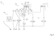
- FIG. 2 is another material testing machine 101 shown by its schematically illustrated computerized hydraulic circuit, the numerous components and configurations according to the material testing machine 1 from FIG. 1 having.
- the explanations to FIG. 1 also apply to the embodiment according to FIG. 2 for identical or even identical assemblies and components; it may therefore be up FIG. 1 in the place of a full explanation.
- a fluid-isolation valve 140 is arranged in the functional center of the schematic circuit, which can assume a first state 141 and a second state 142.
- the fluid control valve 140 is part of the drive unit 110, with which the holder 103 is controlled, operated and controlled.
- the safety closing force 161 is z. B. as a force 164 by an actuator, such as the second actuator 112, provided continuously.
- the second actuator 112 is arranged in the first actuator 111.
- the second actuator 112 moves the clamping piston 130 in a closed position 105, in particular to the material sample 199.
- the closing phase fluid (not shown) is pushed out of the retention chamber 124 by the actuating force 164.
- the actuating force 164 forms a displacement pressure, which is applied via the first valve control line 151 to the drive side 147 of the fluid control valve 140.
- the secondary control side 148 of the fluid control valve 140 can be actuated via the second valve control line 152.
- the Control unit 186 is used to actuate the switching valve 191.
- the control unit 186 includes a control computer PC of the material testing machine 101.
- the control computer PC can emit a control signal 190, the z. B.
- the control signal 190 passes through the Umschaltsignaltechnisch 157 to the switching valve 191.
- the control signal 190 is z. B. after a start time 0 to an actuation time t1.
- the actuating signal 190 activates the electromagnetically actuatable switching valve 191, so that the switching valve 191 changes to the operating state 189.
- the actuation state 189 corresponds to the second position 94 of the switching valve 91 in FIG FIG. 1 ,
- the circuit after FIG. 2 This makes it easier compared to the circuit after FIG. 1 designed that the second switching valve 92 for the (in FIG. 2 to see) drive unit 186 is not provided or required.
- the operating state 189 is taken against a spring bias of the switching valve 191.
- the pressure from the pressure source 197 In the spring biased preferred position of the switching valve 191, the pressure from the pressure source 197, as in FIG. 2 shown, locked.
- the pressure from the pressure source 197 via the switching valve 191 and through the second valve control line 152 at the secondary control side 148 of the fluid control valve 140 to the fluid control valve 140, depending on the pressure on the drive side 147, in the second state 142nd turn on.
- the fluid control valve 140 is to have the highest possible safety, only via control pressures through valve control lines 151, 152 switchable.
- pressure is supplied from the pressure source 197 to the clamping piston 130, which acts in the same direction to the actuating force 164 on the clamping piston 164.
- control lines such as the control lines 151, 152, are shown in phantom to better distinguish them from pressure lines in the hydraulic circuits.
- a secure remote control of the material testing machine 101, in particular on a control computer PC is thus possible.
- FIG. 3 are based on a partial representation of selected areas of the circuits according to FIG. 1 and FIG. 2 further advantageous examples of a material testing machine 201 shown.
- FIG. 3 illustrates areas around an actuator such as the actuator 11, 111 or the actuator 13, 113 as an actuator 203 in some detail, in addition to or as an alternative to those in FIGS FIGS. 1 and 2 shown embodiments can be realized.
- a holder 203 is shown schematically.
- the actuator 211 presses against the material sample 299 with the clamping jaw 207, as a result of which the tensioner 238 can securely hold the material sample 299 by means of the actuator 211 and the bearing 298 '.
- the clamping jaw 207 rests with the clamping surface 234 'on the material sample 299.
- the retention chamber 224 of the actuator 211 is directly connected to the fluid control valve 240 via the first valve control line 251 (compare the corresponding fluid control valves 40, 140 and their hydraulic supply from the pressure source 97, 197 in FIG FIG. 1 respectively. FIG. 2 and the secondary side terminals).
- the pressure (medium) line 250 starting from the fluid control valve 240, is connected via the connection 228 with the movement chamber 223 of the actuator 211.
- a clamping pressure 270 can be applied to the clamping surface 234 via the connection 228.
- the movable support surface 232 limits the retention chamber 224.
- the retention surface 232 is connected via the first valve control line 251 by means of a further switching valve (not shown, see switching valve 78 in FIG. 1 ) acted upon by fluid pressure. If a fluid flows into the retention chamber 224 with its pressure, a stagnation pressure 268 moves the tensioning piston 230 away from the material sample 299.
- the preferred position of the clamping piston 230 with the clamping jaw 207 on the material sample 299 is occupied by one of the force limiting units 260, 260 'shown by way of example, which in particular provide the actuating force 261 if at least one force limiting unit 260, 260' corresponding to the examples is present.
- the length of the pressure or force arrows indicates only a magnitude size, but it should not be understood as a concrete representation of a magnitude relation of the pressures or forces present. The exact interpretation of the relation is determined by the respective application.
- a second actuator 214 is provided, which is supplied via a fluid pressure limiter 280.
- a fluid pressure acts on the drive surface 233 and creates a closing pressure 269 in the movement chamber 223 '.
- the second actuator 214 the operates in the sense of a hydraulic actuator, another second actuator 214 ', which operates like a spring actuator, may be present.
- the force-limiting unit 260 ' comprises as the second actuator 214' a spring 262 whose spring force is limiting for the safety force vector 261.
- the spring 262 may provide a closing pressure 269 'in one embodiment. The closing pressure 269 'moves via the mechanical connection 295 the clamping piston 230 against the direction of the stopping pressure 268 until the Clamping surface 234 'rests on the material sample 299. Both the fluid pressure cylinder unit 263 and the spring 262 can in this case be arranged outside of the first actuator 211. This makes it easier to control the reliable operation of the force-limiting units 260, 261.
- FIG. 3 the components of the force-limiting unit 260, 260 'are shown with a lateral offset to the clamping piston 230, whereby the schematic representation of the embodiments are particularly easy to see.
- a force-limiting unit 260, 260 ' is preferably arranged aligned with an actuator 211, wherein the safety force vector 261 is directed on an axis with the clamping pressure 270 along the clamping piston 230.
- the safety force vector 261 is preferably introduced by a second actuator 214, 214 'disposed on a central axis (not shown) of the tensioning piston 230.
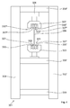
- FIG. 4 shows as a material testing machine 301 in a simplified representation of the type of column testing machine.
- the column testing machine which is sometimes referred to as a traverse testing machine, has at least two columns, a first column 302 and a second column 302 '. Traverses 309, 309 ', 309 "are mounted transversely to the direction of extension of the columns 302, 302' on the two columns 302, 302 '.
- the two outer cross members 309, 309" are available as a base cross member 309 and as a head cross member 309 " Base truss 309 and the headrail 309 "there is a trolley 309 '.
- the trolley 309 ' is located in the middle region on the two columns 302, 302'.
- a force can be applied to a sample 399.
- the two outer trusses, the base truss 309 and the head truss 309 "form a frame together with the pillars 302, 302.
- sample 399 is clamped between jaws 307, 307 ', 307 ", 307'"
- clamping jaws 307, 307 ', 307 ", 307'” are clamped by tensioning pistons 330, 330 ', 330 "
- Each clamping jaw 307, 307 ', 307 ", 307'” is associated with its own tensioning piston 330, 330 ', 330 ", 330'", using the tensioning pistons 330, 330 ', 330 ", 330'.
- the holders 303, 303 ' can be brought into a closed position 305, 305' In the closed position 305, 305 ', the part of the sample 399 resting against the clamping jaws 307, 307', 307 ", 307 '" is frictionally held Closed position 308 of the clamping jaws 307, 307 ' corresponds to the closed position 305 of the holder 303. If the jaws 307, 307 'in a closed position 308, so is the holder 303, which includes the jaws 307, 307', in a closed position 308.
- a test force can be applied to the sample 399 by means of a method of the traverse truss 309.
- the test force or the forces acting in the material testing machine 301, which act in particular on the sample 399, can be measured with a force transducer 306
- a favorable location for receiving the measuring force by means of force transducer 306 is an underside of the head traverse 309 ", preferably in the immediate axial extension of a clamping direction of the sample 399.
- the second holder 303 'serves as a counter-holder.
- the first holder 303 serves as a force-acting holder.
- the force transducer 306 rests on the head traverse 309 ".
- the material testing machine 301 can be equipped with a drive unit with a drive unit such as the drive unit 10 (FIG. FIG. 1 ) or the drive unit 110 (FIG. FIG. 2 ) is configured.
- the Kraftkraftbegrenzungsakuen 260, 260 ' may be designed as a retrofit kit.
- the Kraftkraftbegrenzungsticianen 260, 260 'can also be used to move a holder for a protective device, such as a protective cage, so as to prevent the access z. B. to a material testing machine that works with very high forces to secure.
- Embodiment options shown can also be interconnected in any form. In particular, elements of one embodiment may be advantageously combined with another embodiment.
- FIG. 4 explained application of the invention is also applicable to column testing machines, which form a frame for a test room with more or fewer columns.
- the invention can be used in C-shaped testing machines, so-called single-column testing machines, as well - and also retrofit - as in material testing machines with three, four and more columns.
Landscapes
- Physics & Mathematics (AREA)
- Health & Medical Sciences (AREA)
- Life Sciences & Earth Sciences (AREA)
- Chemical & Material Sciences (AREA)
- Analytical Chemistry (AREA)
- Biochemistry (AREA)
- General Health & Medical Sciences (AREA)
- General Physics & Mathematics (AREA)
- Immunology (AREA)
- Pathology (AREA)
- Investigating Strength Of Materials By Application Of Mechanical Stress (AREA)
Applications Claiming Priority (1)
| Application Number | Priority Date | Filing Date | Title |
|---|---|---|---|
| DE102015201993.4A DE102015201993A1 (de) | 2015-02-05 | 2015-02-05 | Materialprobenhalter mit Ansteuereinheit |
Publications (2)
| Publication Number | Publication Date |
|---|---|
| EP3056891A1 true EP3056891A1 (fr) | 2016-08-17 |
| EP3056891B1 EP3056891B1 (fr) | 2017-09-27 |
Family
ID=55299275
Family Applications (1)
| Application Number | Title | Priority Date | Filing Date |
|---|---|---|---|
| EP16153443.3A Active EP3056891B1 (fr) | 2015-02-05 | 2016-01-29 | Support d'echantillon de materiau comprenant une unite de commande |
Country Status (3)
| Country | Link |
|---|---|
| US (1) | US10012575B2 (fr) |
| EP (1) | EP3056891B1 (fr) |
| DE (1) | DE102015201993A1 (fr) |
Families Citing this family (14)
| Publication number | Priority date | Publication date | Assignee | Title |
|---|---|---|---|---|
| EP3123144A4 (fr) * | 2014-03-28 | 2017-12-13 | United Technologies Corporation | Appareil et procédé de test de matériau |
| US10184864B2 (en) * | 2015-12-10 | 2019-01-22 | Mechanical Testing Services, Llc | Intelligent automated load control system and method |
| US10921226B2 (en) * | 2018-05-31 | 2021-02-16 | Electric Power Research Institute, Inc. | Apparatus and method for testing mechanical materials |
| CN109030189A (zh) * | 2018-07-13 | 2018-12-18 | 山西省机电设计研究院 | V型夹头万能液压材料试验机水平夹具 |
| DE102018219449A1 (de) * | 2018-11-14 | 2020-05-14 | Mag Ias Gmbh | Prüfeinrichtung zur Anlageprüfung eines Objekts an einer Spannvorrichtung |
| US11726018B2 (en) * | 2018-11-30 | 2023-08-15 | Illinois Tool Works Inc. | Safety system interfaces and material testing systems including safety system interfaces |
| US11879871B2 (en) * | 2018-11-30 | 2024-01-23 | Illinois Tool Works Inc. | Safety systems requiring intentional function activation and material testing systems including safety systems requiring intentional function activation |
| US11592375B2 (en) | 2019-03-28 | 2023-02-28 | Illinois Tool Works Inc. | Collision mitigation apparatus material testing systems having collision mitigation apparatus |
| US12050206B2 (en) * | 2020-02-09 | 2024-07-30 | Illinois Tool Works Inc. | Pneumatic grip systems and material testing systems including pneumatic grip systems |
| JP7582125B2 (ja) * | 2020-11-26 | 2024-11-13 | 株式会社島津製作所 | 試験機 |
| US20240011752A1 (en) * | 2022-07-07 | 2024-01-11 | Illinois Tool Works Inc. | Systems and methods to measure specimen dimensions |
| WO2024035756A1 (fr) * | 2022-08-09 | 2024-02-15 | Board Of Trustees Of Michigan State University | Système de mandrin de serrage pour test uniaxial |
| CN117740590B (zh) * | 2023-12-22 | 2024-10-29 | 江苏锦汇高分子科技有限公司 | 一种橡胶的磨耗试验装置 |
| DE202025100185U1 (de) | 2025-01-15 | 2025-02-03 | Thyssenkrupp Steel Europe Ag | Materialprüfvorrichtung zum Prüfen von Materialproben |
Citations (14)
| Publication number | Priority date | Publication date | Assignee | Title |
|---|---|---|---|---|
| US2805447A (en) | 1953-11-05 | 1957-09-10 | Voges Fred William | Safety circuit for molding machine |
| DE1552653B1 (de) * | 1966-02-09 | 1970-11-19 | Peiseler Fa J G | Pneumatische oder hydraulische Einspannvorrichtung |
| DE2158700A1 (de) | 1971-11-26 | 1973-05-30 | Festo Maschf Stoll G | Sicherheitseinrichtung zum steuern des druckmittelzuflusses zu einer verbraucherstelle |
| DE2229538A1 (de) | 1972-06-16 | 1973-10-18 | Max Mayer | Pneumatische spannvorrichtung |
| DE2839341C3 (de) | 1978-09-09 | 1981-06-19 | Daimler-Benz Ag, 7000 Stuttgart | Pneumatisches Flip-Flop |
| DE3912075A1 (de) | 1989-04-10 | 1990-10-11 | Bam Bundesanstalt Matforschung | Vorrichtung und verfahren zur einachsigen mechanischen werkstoffpruefung |
| DE4228846C2 (de) | 1992-08-29 | 1994-05-05 | Artur Dipl Ing Gruellmeier | Pneumatischer druckübersetzter Arbeitszylinder mit Eil- und Krafthub |
| DE10161703B4 (de) | 2001-12-15 | 2005-02-24 | Festo Ag & Co.Kg | Entlüftungseinrichtung für einen Pneumatikantrieb |
| DE112006003923T5 (de) * | 2006-06-12 | 2009-04-30 | Shimadzu Corp. | Materialprüfmaschine |
| CN101608987A (zh) | 2009-07-24 | 2009-12-23 | 太原重工股份有限公司 | 水压试管机中钢管夹紧装置的液压控制系统 |
| DE102009036247A1 (de) | 2009-08-05 | 2011-02-10 | Zwick Gmbh & Co. Kg | Vorrichtung zur Durchführung von Bauteil- und Werkstoffprüfungen an Proben |
| DE112009005323B4 (de) | 2009-10-17 | 2013-04-18 | Messphysik Materials Testing Gmbh | Hebelarmprüfmaschine |
| EP2631496A2 (fr) | 2012-02-23 | 2013-08-28 | Zwick GmbH&Co. Kg | Commande fluidique, notamment commande pneumatique pour machines de contrôle |
| EP2677296A2 (fr) | 2012-06-22 | 2013-12-25 | Zwick GmbH&Co. Kg | Dispositif d'orientation d'un dispositif de contrôle |
Family Cites Families (8)
| Publication number | Priority date | Publication date | Assignee | Title |
|---|---|---|---|---|
| US3375710A (en) * | 1965-05-21 | 1968-04-02 | Instron Corp | Materials testing grip |
| DE2349686C2 (de) * | 1973-10-03 | 1975-01-30 | Carl Schenck Ag, 6100 Darmstadt | Einspannvorrichtung |
| US5581040A (en) * | 1995-11-01 | 1996-12-03 | Lin; Wei-Hwang | Multi-functional hydraulic grip |
| FR2807795B1 (fr) * | 2000-04-18 | 2002-07-12 | Crouzet Automatismes | Dispositif de commande d'un actionneur |
| US9964428B2 (en) * | 2008-10-09 | 2018-05-08 | Cascade Corporation | Equalized hydraulic clamp force control |
| DE102009036246A1 (de) * | 2009-08-05 | 2011-02-10 | Zwick Gmbh & Co. Kg | Probenhalter zum Spannen von Werkstücken |
| US20130152292A1 (en) * | 2011-12-19 | 2013-06-20 | Defond Components Limited | Liquid-operated actuator assembly |
| US9228334B2 (en) * | 2011-12-19 | 2016-01-05 | Defond Components Limited | Liquid-operated actuator assembly, particularly for a flush toilet, and flush toilet incorporating the assembly |
-
2015
- 2015-02-05 DE DE102015201993.4A patent/DE102015201993A1/de not_active Withdrawn
-
2016
- 2016-01-29 EP EP16153443.3A patent/EP3056891B1/fr active Active
- 2016-02-05 US US15/016,957 patent/US10012575B2/en active Active
Patent Citations (18)
| Publication number | Priority date | Publication date | Assignee | Title |
|---|---|---|---|---|
| US2805447A (en) | 1953-11-05 | 1957-09-10 | Voges Fred William | Safety circuit for molding machine |
| DE1552653B1 (de) * | 1966-02-09 | 1970-11-19 | Peiseler Fa J G | Pneumatische oder hydraulische Einspannvorrichtung |
| DE1552653C2 (fr) | 1966-02-09 | 1974-08-15 | Fa. J.Gottlieb Peiseler, 5630 Remscheid | |
| DE2158700A1 (de) | 1971-11-26 | 1973-05-30 | Festo Maschf Stoll G | Sicherheitseinrichtung zum steuern des druckmittelzuflusses zu einer verbraucherstelle |
| DE2229538A1 (de) | 1972-06-16 | 1973-10-18 | Max Mayer | Pneumatische spannvorrichtung |
| DE2839341C3 (de) | 1978-09-09 | 1981-06-19 | Daimler-Benz Ag, 7000 Stuttgart | Pneumatisches Flip-Flop |
| DE3912075A1 (de) | 1989-04-10 | 1990-10-11 | Bam Bundesanstalt Matforschung | Vorrichtung und verfahren zur einachsigen mechanischen werkstoffpruefung |
| DE4228846C2 (de) | 1992-08-29 | 1994-05-05 | Artur Dipl Ing Gruellmeier | Pneumatischer druckübersetzter Arbeitszylinder mit Eil- und Krafthub |
| DE10161703B4 (de) | 2001-12-15 | 2005-02-24 | Festo Ag & Co.Kg | Entlüftungseinrichtung für einen Pneumatikantrieb |
| DE112006003923T5 (de) * | 2006-06-12 | 2009-04-30 | Shimadzu Corp. | Materialprüfmaschine |
| DE112006003923B4 (de) | 2006-06-12 | 2013-06-06 | Shimadzu Corp. | Materialprüfmaschine |
| CN101608987A (zh) | 2009-07-24 | 2009-12-23 | 太原重工股份有限公司 | 水压试管机中钢管夹紧装置的液压控制系统 |
| CN101608987B (zh) * | 2009-07-24 | 2011-05-18 | 太原重工股份有限公司 | 水压试管机中钢管夹紧装置的液压控制系统 |
| DE102009036247A1 (de) | 2009-08-05 | 2011-02-10 | Zwick Gmbh & Co. Kg | Vorrichtung zur Durchführung von Bauteil- und Werkstoffprüfungen an Proben |
| DE112009005323B4 (de) | 2009-10-17 | 2013-04-18 | Messphysik Materials Testing Gmbh | Hebelarmprüfmaschine |
| EP2631496A2 (fr) | 2012-02-23 | 2013-08-28 | Zwick GmbH&Co. Kg | Commande fluidique, notamment commande pneumatique pour machines de contrôle |
| DE102012101459A1 (de) | 2012-02-23 | 2013-08-29 | Zwick Gmbh & Co. Kg | Fluidische Steuerung, insbesondere pneumatische Steuerung für Prüfmaschinen |
| EP2677296A2 (fr) | 2012-06-22 | 2013-12-25 | Zwick GmbH&Co. Kg | Dispositif d'orientation d'un dispositif de contrôle |
Also Published As
| Publication number | Publication date |
|---|---|
| US20160231210A1 (en) | 2016-08-11 |
| EP3056891B1 (fr) | 2017-09-27 |
| US10012575B2 (en) | 2018-07-03 |
| DE102015201993A1 (de) | 2016-08-11 |
Similar Documents
| Publication | Publication Date | Title |
|---|---|---|
| EP3056891B1 (fr) | Support d'echantillon de materiau comprenant une unite de commande | |
| DE3840395C2 (de) | Steuerung einer Blechbearbeitungspresse | |
| DE102005014416B4 (de) | Luftservozylindervorrichtung und Steuerverfahren hierfür | |
| EP3478452B1 (fr) | Procédé servant à faire fonctionner un appareil portatif à fonctionnement hydraulique, ainsi qu'appareil portatif à fonctionnement hydraulique | |
| EP2848398B1 (fr) | Dispositif et procédé destinés à empêcher la rupture d'un outil lors du coupage fin et/ou du déformage d'une pièce usinée | |
| EP1758697B1 (fr) | Procede et presse de decoupe de tole a haute resistance | |
| EP3115190B1 (fr) | Dispositif et procede de commande de l'entrainement principal d'une presse pour decoupage de precision | |
| EP3115191A1 (fr) | Procédé et dispositif de réduction du choc de coupe dans une presse de découpage fin | |
| DE2242067B2 (de) | Längenverstellbarer Pleuel für eine Presse mit hydraulischer Überlastsicherung | |
| EP1782897B1 (fr) | Presse avec amortissement des chocs de coupe. | |
| DE2824361C2 (de) | Vorrichtung zum Konstanthalten der in einem Kabel oder dergleichen herrschenden Zugspannung | |
| DE2940232A1 (de) | Hydraulische stossdaempfvorrichtung, insbesondere fuer abscherpressen | |
| EP3056291B1 (fr) | Presse dotée d'un amortisseur de choc de coupe | |
| EP2631496B1 (fr) | Commande fluidique, notamment commande pneumatique pour machines de contrôle | |
| DE10339004B4 (de) | Hydraulische Presse | |
| DE10005023A1 (de) | Presse | |
| WO2018015370A1 (fr) | Procédé et dispositif pour cisailler un matériau en tige | |
| DE2432774B2 (de) | Presse, insbesondere Feinschneidpresse | |
| EP2586544B1 (fr) | Machine-outil avec un dispositif de butée et procédé de fonctionnement de la machine-outil | |
| EP2019240B1 (fr) | Soupape de commande de charge hydraulique à circuit RC | |
| DE2621726C2 (de) | Schnittschlagdämpfungseinrichtung an Pressen | |
| DE202012002940U1 (de) | Spannvorrichtung | |
| DE102009001211B4 (de) | Tiefziehvorrichtung für Metallbleche | |
| DE10229276A1 (de) | Vorrichtung zur Überlastsicherung in einer Presse | |
| DE3211795C2 (de) | Sicherheitseinrichtung an einer druckmittelbetätigbaren Werkstück-Spannvorrichtung |
Legal Events
| Date | Code | Title | Description |
|---|---|---|---|
| PUAI | Public reference made under article 153(3) epc to a published international application that has entered the european phase |
Free format text: ORIGINAL CODE: 0009012 |
|
| AK | Designated contracting states |
Kind code of ref document: A1 Designated state(s): AL AT BE BG CH CY CZ DE DK EE ES FI FR GB GR HR HU IE IS IT LI LT LU LV MC MK MT NL NO PL PT RO RS SE SI SK SM TR |
|
| AX | Request for extension of the european patent |
Extension state: BA ME |
|
| 17P | Request for examination filed |
Effective date: 20161118 |
|
| RBV | Designated contracting states (corrected) |
Designated state(s): AL AT BE BG CH CY CZ DE DK EE ES FI FR GB GR HR HU IE IS IT LI LT LU LV MC MK MT NL NO PL PT RO RS SE SI SK SM TR |
|
| RIC1 | Information provided on ipc code assigned before grant |
Ipc: G01N 3/36 20060101AFI20161202BHEP |
|
| 17Q | First examination report despatched |
Effective date: 20161215 |
|
| GRAP | Despatch of communication of intention to grant a patent |
Free format text: ORIGINAL CODE: EPIDOSNIGR1 |
|
| INTG | Intention to grant announced |
Effective date: 20170426 |
|
| GRAS | Grant fee paid |
Free format text: ORIGINAL CODE: EPIDOSNIGR3 |
|
| GRAA | (expected) grant |
Free format text: ORIGINAL CODE: 0009210 |
|
| AK | Designated contracting states |
Kind code of ref document: B1 Designated state(s): AL AT BE BG CH CY CZ DE DK EE ES FI FR GB GR HR HU IE IS IT LI LT LU LV MC MK MT NL NO PL PT RO RS SE SI SK SM TR |
|
| REG | Reference to a national code |
Ref country code: GB Ref legal event code: FG4D Free format text: NOT ENGLISH |
|
| REG | Reference to a national code |
Ref country code: CH Ref legal event code: EP |
|
| REG | Reference to a national code |
Ref country code: AT Ref legal event code: REF Ref document number: 932391 Country of ref document: AT Kind code of ref document: T Effective date: 20171015 |
|
| REG | Reference to a national code |
Ref country code: IE Ref legal event code: FG4D Free format text: LANGUAGE OF EP DOCUMENT: GERMAN |
|
| REG | Reference to a national code |
Ref country code: DE Ref legal event code: R096 Ref document number: 502016000162 Country of ref document: DE |
|
| REG | Reference to a national code |
Ref country code: FR Ref legal event code: PLFP Year of fee payment: 3 |
|
| PG25 | Lapsed in a contracting state [announced via postgrant information from national office to epo] |
Ref country code: HR Free format text: LAPSE BECAUSE OF FAILURE TO SUBMIT A TRANSLATION OF THE DESCRIPTION OR TO PAY THE FEE WITHIN THE PRESCRIBED TIME-LIMIT Effective date: 20170927 Ref country code: SE Free format text: LAPSE BECAUSE OF FAILURE TO SUBMIT A TRANSLATION OF THE DESCRIPTION OR TO PAY THE FEE WITHIN THE PRESCRIBED TIME-LIMIT Effective date: 20170927 Ref country code: FI Free format text: LAPSE BECAUSE OF FAILURE TO SUBMIT A TRANSLATION OF THE DESCRIPTION OR TO PAY THE FEE WITHIN THE PRESCRIBED TIME-LIMIT Effective date: 20170927 Ref country code: LT Free format text: LAPSE BECAUSE OF FAILURE TO SUBMIT A TRANSLATION OF THE DESCRIPTION OR TO PAY THE FEE WITHIN THE PRESCRIBED TIME-LIMIT Effective date: 20170927 Ref country code: NO Free format text: LAPSE BECAUSE OF FAILURE TO SUBMIT A TRANSLATION OF THE DESCRIPTION OR TO PAY THE FEE WITHIN THE PRESCRIBED TIME-LIMIT Effective date: 20171227 |
|
| REG | Reference to a national code |
Ref country code: NL Ref legal event code: MP Effective date: 20170927 |
|
| REG | Reference to a national code |
Ref country code: LT Ref legal event code: MG4D |
|
| PG25 | Lapsed in a contracting state [announced via postgrant information from national office to epo] |
Ref country code: RS Free format text: LAPSE BECAUSE OF FAILURE TO SUBMIT A TRANSLATION OF THE DESCRIPTION OR TO PAY THE FEE WITHIN THE PRESCRIBED TIME-LIMIT Effective date: 20170927 Ref country code: LV Free format text: LAPSE BECAUSE OF FAILURE TO SUBMIT A TRANSLATION OF THE DESCRIPTION OR TO PAY THE FEE WITHIN THE PRESCRIBED TIME-LIMIT Effective date: 20170927 Ref country code: BG Free format text: LAPSE BECAUSE OF FAILURE TO SUBMIT A TRANSLATION OF THE DESCRIPTION OR TO PAY THE FEE WITHIN THE PRESCRIBED TIME-LIMIT Effective date: 20171227 Ref country code: GR Free format text: LAPSE BECAUSE OF FAILURE TO SUBMIT A TRANSLATION OF THE DESCRIPTION OR TO PAY THE FEE WITHIN THE PRESCRIBED TIME-LIMIT Effective date: 20171228 |
|
| PG25 | Lapsed in a contracting state [announced via postgrant information from national office to epo] |
Ref country code: NL Free format text: LAPSE BECAUSE OF FAILURE TO SUBMIT A TRANSLATION OF THE DESCRIPTION OR TO PAY THE FEE WITHIN THE PRESCRIBED TIME-LIMIT Effective date: 20170927 |
|
| PG25 | Lapsed in a contracting state [announced via postgrant information from national office to epo] |
Ref country code: ES Free format text: LAPSE BECAUSE OF FAILURE TO SUBMIT A TRANSLATION OF THE DESCRIPTION OR TO PAY THE FEE WITHIN THE PRESCRIBED TIME-LIMIT Effective date: 20170927 Ref country code: RO Free format text: LAPSE BECAUSE OF FAILURE TO SUBMIT A TRANSLATION OF THE DESCRIPTION OR TO PAY THE FEE WITHIN THE PRESCRIBED TIME-LIMIT Effective date: 20170927 Ref country code: CZ Free format text: LAPSE BECAUSE OF FAILURE TO SUBMIT A TRANSLATION OF THE DESCRIPTION OR TO PAY THE FEE WITHIN THE PRESCRIBED TIME-LIMIT Effective date: 20170927 |
|
| PG25 | Lapsed in a contracting state [announced via postgrant information from national office to epo] |
Ref country code: SK Free format text: LAPSE BECAUSE OF FAILURE TO SUBMIT A TRANSLATION OF THE DESCRIPTION OR TO PAY THE FEE WITHIN THE PRESCRIBED TIME-LIMIT Effective date: 20170927 Ref country code: SM Free format text: LAPSE BECAUSE OF FAILURE TO SUBMIT A TRANSLATION OF THE DESCRIPTION OR TO PAY THE FEE WITHIN THE PRESCRIBED TIME-LIMIT Effective date: 20170927 Ref country code: EE Free format text: LAPSE BECAUSE OF FAILURE TO SUBMIT A TRANSLATION OF THE DESCRIPTION OR TO PAY THE FEE WITHIN THE PRESCRIBED TIME-LIMIT Effective date: 20170927 Ref country code: IT Free format text: LAPSE BECAUSE OF FAILURE TO SUBMIT A TRANSLATION OF THE DESCRIPTION OR TO PAY THE FEE WITHIN THE PRESCRIBED TIME-LIMIT Effective date: 20170927 Ref country code: IS Free format text: LAPSE BECAUSE OF FAILURE TO SUBMIT A TRANSLATION OF THE DESCRIPTION OR TO PAY THE FEE WITHIN THE PRESCRIBED TIME-LIMIT Effective date: 20180127 |
|
| REG | Reference to a national code |
Ref country code: DE Ref legal event code: R097 Ref document number: 502016000162 Country of ref document: DE |
|
| PG25 | Lapsed in a contracting state [announced via postgrant information from national office to epo] |
Ref country code: DK Free format text: LAPSE BECAUSE OF FAILURE TO SUBMIT A TRANSLATION OF THE DESCRIPTION OR TO PAY THE FEE WITHIN THE PRESCRIBED TIME-LIMIT Effective date: 20170927 |
|
| PLBE | No opposition filed within time limit |
Free format text: ORIGINAL CODE: 0009261 |
|
| STAA | Information on the status of an ep patent application or granted ep patent |
Free format text: STATUS: NO OPPOSITION FILED WITHIN TIME LIMIT |
|
| PG25 | Lapsed in a contracting state [announced via postgrant information from national office to epo] |
Ref country code: PL Free format text: LAPSE BECAUSE OF FAILURE TO SUBMIT A TRANSLATION OF THE DESCRIPTION OR TO PAY THE FEE WITHIN THE PRESCRIBED TIME-LIMIT Effective date: 20170927 |
|
| 26N | No opposition filed |
Effective date: 20180628 |
|
| PG25 | Lapsed in a contracting state [announced via postgrant information from national office to epo] |
Ref country code: MT Free format text: LAPSE BECAUSE OF FAILURE TO SUBMIT A TRANSLATION OF THE DESCRIPTION OR TO PAY THE FEE WITHIN THE PRESCRIBED TIME-LIMIT Effective date: 20170927 |
|
| PG25 | Lapsed in a contracting state [announced via postgrant information from national office to epo] |
Ref country code: LU Free format text: LAPSE BECAUSE OF NON-PAYMENT OF DUE FEES Effective date: 20180129 |
|
| REG | Reference to a national code |
Ref country code: IE Ref legal event code: MM4A |
|
| REG | Reference to a national code |
Ref country code: BE Ref legal event code: MM Effective date: 20180131 |
|
| PG25 | Lapsed in a contracting state [announced via postgrant information from national office to epo] |
Ref country code: BE Free format text: LAPSE BECAUSE OF NON-PAYMENT OF DUE FEES Effective date: 20180131 Ref country code: SI Free format text: LAPSE BECAUSE OF FAILURE TO SUBMIT A TRANSLATION OF THE DESCRIPTION OR TO PAY THE FEE WITHIN THE PRESCRIBED TIME-LIMIT Effective date: 20170927 |
|
| PG25 | Lapsed in a contracting state [announced via postgrant information from national office to epo] |
Ref country code: IE Free format text: LAPSE BECAUSE OF NON-PAYMENT OF DUE FEES Effective date: 20180129 |
|
| REG | Reference to a national code |
Ref country code: DE Ref legal event code: R082 Ref document number: 502016000162 Country of ref document: DE Representative=s name: CREMER & CREMER, DE Ref country code: DE Ref legal event code: R081 Ref document number: 502016000162 Country of ref document: DE Owner name: ZWICKROELL GMBH & CO. KG, DE Free format text: FORMER OWNER: ZWICK GMBH & CO. KG, 89079 ULM, DE |
|
| PG25 | Lapsed in a contracting state [announced via postgrant information from national office to epo] |
Ref country code: MC Free format text: LAPSE BECAUSE OF FAILURE TO SUBMIT A TRANSLATION OF THE DESCRIPTION OR TO PAY THE FEE WITHIN THE PRESCRIBED TIME-LIMIT Effective date: 20170927 |
|
| REG | Reference to a national code |
Ref country code: CH Ref legal event code: PL |
|
| PG25 | Lapsed in a contracting state [announced via postgrant information from national office to epo] |
Ref country code: CH Free format text: LAPSE BECAUSE OF NON-PAYMENT OF DUE FEES Effective date: 20190131 Ref country code: LI Free format text: LAPSE BECAUSE OF NON-PAYMENT OF DUE FEES Effective date: 20190131 |
|
| PG25 | Lapsed in a contracting state [announced via postgrant information from national office to epo] |
Ref country code: TR Free format text: LAPSE BECAUSE OF FAILURE TO SUBMIT A TRANSLATION OF THE DESCRIPTION OR TO PAY THE FEE WITHIN THE PRESCRIBED TIME-LIMIT Effective date: 20170927 |
|
| PG25 | Lapsed in a contracting state [announced via postgrant information from national office to epo] |
Ref country code: PT Free format text: LAPSE BECAUSE OF FAILURE TO SUBMIT A TRANSLATION OF THE DESCRIPTION OR TO PAY THE FEE WITHIN THE PRESCRIBED TIME-LIMIT Effective date: 20170927 |
|
| PG25 | Lapsed in a contracting state [announced via postgrant information from national office to epo] |
Ref country code: CY Free format text: LAPSE BECAUSE OF FAILURE TO SUBMIT A TRANSLATION OF THE DESCRIPTION OR TO PAY THE FEE WITHIN THE PRESCRIBED TIME-LIMIT Effective date: 20170927 Ref country code: MK Free format text: LAPSE BECAUSE OF NON-PAYMENT OF DUE FEES Effective date: 20170927 Ref country code: HU Free format text: LAPSE BECAUSE OF FAILURE TO SUBMIT A TRANSLATION OF THE DESCRIPTION OR TO PAY THE FEE WITHIN THE PRESCRIBED TIME-LIMIT; INVALID AB INITIO Effective date: 20160129 |
|
| PG25 | Lapsed in a contracting state [announced via postgrant information from national office to epo] |
Ref country code: AL Free format text: LAPSE BECAUSE OF FAILURE TO SUBMIT A TRANSLATION OF THE DESCRIPTION OR TO PAY THE FEE WITHIN THE PRESCRIBED TIME-LIMIT Effective date: 20170927 |
|
| REG | Reference to a national code |
Ref country code: AT Ref legal event code: MM01 Ref document number: 932391 Country of ref document: AT Kind code of ref document: T Effective date: 20210129 |
|
| PG25 | Lapsed in a contracting state [announced via postgrant information from national office to epo] |
Ref country code: AT Free format text: LAPSE BECAUSE OF NON-PAYMENT OF DUE FEES Effective date: 20210129 |
|
| PGFP | Annual fee paid to national office [announced via postgrant information from national office to epo] |
Ref country code: GB Payment date: 20260123 Year of fee payment: 11 |
|
| PGFP | Annual fee paid to national office [announced via postgrant information from national office to epo] |
Ref country code: DE Payment date: 20251217 Year of fee payment: 11 |
|
| PGFP | Annual fee paid to national office [announced via postgrant information from national office to epo] |
Ref country code: FR Payment date: 20260123 Year of fee payment: 11 |