EP3057208A1 - Moteur à induction synchrone - Google Patents
Moteur à induction synchrone Download PDFInfo
- Publication number
- EP3057208A1 EP3057208A1 EP16152947.4A EP16152947A EP3057208A1 EP 3057208 A1 EP3057208 A1 EP 3057208A1 EP 16152947 A EP16152947 A EP 16152947A EP 3057208 A1 EP3057208 A1 EP 3057208A1
- Authority
- EP
- European Patent Office
- Prior art keywords
- permanent magnets
- induction motor
- rotor core
- synchronous induction
- bearing
- Prior art date
- Legal status (The legal status is an assumption and is not a legal conclusion. Google has not performed a legal analysis and makes no representation as to the accuracy of the status listed.)
- Withdrawn
Links
- 230000001360 synchronised effect Effects 0.000 title claims abstract description 67
- 230000006698 induction Effects 0.000 title claims abstract description 64
- 239000004020 conductor Substances 0.000 claims abstract description 103
- 230000004907 flux Effects 0.000 claims abstract description 14
- 229910000831 Steel Inorganic materials 0.000 claims description 10
- 239000010959 steel Substances 0.000 claims description 10
- 229910000576 Laminated steel Inorganic materials 0.000 claims description 6
- 230000004044 response Effects 0.000 claims description 3
- 230000003247 decreasing effect Effects 0.000 claims description 2
- 229910000976 Electrical steel Inorganic materials 0.000 claims 1
- 238000005266 casting Methods 0.000 description 6
- 238000013459 approach Methods 0.000 description 4
- 230000007246 mechanism Effects 0.000 description 3
- 238000004804 winding Methods 0.000 description 3
- 239000000853 adhesive Substances 0.000 description 2
- 230000001070 adhesive effect Effects 0.000 description 2
- 229910052782 aluminium Inorganic materials 0.000 description 2
- XAGFODPZIPBFFR-UHFFFAOYSA-N aluminium Chemical compound [Al] XAGFODPZIPBFFR-UHFFFAOYSA-N 0.000 description 2
- 230000008901 benefit Effects 0.000 description 2
- 230000007423 decrease Effects 0.000 description 2
- 239000000696 magnetic material Substances 0.000 description 2
- 238000012986 modification Methods 0.000 description 2
- 230000004048 modification Effects 0.000 description 2
- 230000009471 action Effects 0.000 description 1
- 230000004323 axial length Effects 0.000 description 1
- 230000000977 initiatory effect Effects 0.000 description 1
- 239000007788 liquid Substances 0.000 description 1
- 238000004519 manufacturing process Methods 0.000 description 1
- 239000000463 material Substances 0.000 description 1
- 229910052751 metal Inorganic materials 0.000 description 1
- 239000002184 metal Substances 0.000 description 1
- 238000000034 method Methods 0.000 description 1
- 229910001220 stainless steel Inorganic materials 0.000 description 1
- 239000010935 stainless steel Substances 0.000 description 1
- 238000003466 welding Methods 0.000 description 1
Images


Classifications
-
- H—ELECTRICITY
- H02—GENERATION; CONVERSION OR DISTRIBUTION OF ELECTRIC POWER
- H02K—DYNAMO-ELECTRIC MACHINES
- H02K1/00—Details of the magnetic circuit
- H02K1/06—Details of the magnetic circuit characterised by the shape, form or construction
- H02K1/22—Rotating parts of the magnetic circuit
- H02K1/27—Rotor cores with permanent magnets
- H02K1/2786—Outer rotors
- H02K1/2787—Outer rotors the magnetisation axis of the magnets being perpendicular to the rotor axis
- H02K1/2789—Outer rotors the magnetisation axis of the magnets being perpendicular to the rotor axis the rotor consisting of two or more circumferentially positioned magnets
- H02K1/2791—Surface mounted magnets; Inset magnets
-
- H—ELECTRICITY
- H02—GENERATION; CONVERSION OR DISTRIBUTION OF ELECTRIC POWER
- H02K—DYNAMO-ELECTRIC MACHINES
- H02K21/00—Synchronous motors having permanent magnets; Synchronous generators having permanent magnets
- H02K21/12—Synchronous motors having permanent magnets; Synchronous generators having permanent magnets with stationary armatures and rotating magnets
- H02K21/22—Synchronous motors having permanent magnets; Synchronous generators having permanent magnets with stationary armatures and rotating magnets with magnets rotating around the armatures, e.g. flywheel magnetos
-
- H—ELECTRICITY
- H02—GENERATION; CONVERSION OR DISTRIBUTION OF ELECTRIC POWER
- H02K—DYNAMO-ELECTRIC MACHINES
- H02K1/00—Details of the magnetic circuit
- H02K1/06—Details of the magnetic circuit characterised by the shape, form or construction
- H02K1/22—Rotating parts of the magnetic circuit
- H02K1/27—Rotor cores with permanent magnets
- H02K1/2706—Inner rotors
- H02K1/272—Inner rotors the magnetisation axis of the magnets being perpendicular to the rotor axis
- H02K1/274—Inner rotors the magnetisation axis of the magnets being perpendicular to the rotor axis the rotor consisting of two or more circumferentially positioned magnets
- H02K1/2753—Inner rotors the magnetisation axis of the magnets being perpendicular to the rotor axis the rotor consisting of two or more circumferentially positioned magnets the rotor consisting of magnets or groups of magnets arranged with alternating polarity
- H02K1/276—Magnets embedded in the magnetic core, e.g. interior permanent magnets [IPM]
-
- H—ELECTRICITY
- H02—GENERATION; CONVERSION OR DISTRIBUTION OF ELECTRIC POWER
- H02K—DYNAMO-ELECTRIC MACHINES
- H02K21/00—Synchronous motors having permanent magnets; Synchronous generators having permanent magnets
- H02K21/46—Motors having additional short-circuited winding for starting as an asynchronous motor
-
- H—ELECTRICITY
- H02—GENERATION; CONVERSION OR DISTRIBUTION OF ELECTRIC POWER
- H02K—DYNAMO-ELECTRIC MACHINES
- H02K7/00—Arrangements for handling mechanical energy structurally associated with dynamo-electric machines, e.g. structural association with mechanical driving motors or auxiliary dynamo-electric machines
- H02K7/08—Structural association with bearings
- H02K7/086—Structural association with bearings radially supporting the rotor around a fixed spindle; radially supporting the rotor directly
-
- H—ELECTRICITY
- H02—GENERATION; CONVERSION OR DISTRIBUTION OF ELECTRIC POWER
- H02K—DYNAMO-ELECTRIC MACHINES
- H02K1/00—Details of the magnetic circuit
- H02K1/06—Details of the magnetic circuit characterised by the shape, form or construction
- H02K1/22—Rotating parts of the magnetic circuit
- H02K1/26—Rotor cores with slots for windings
- H02K1/265—Shape, form or location of the slots
-
- H—ELECTRICITY
- H02—GENERATION; CONVERSION OR DISTRIBUTION OF ELECTRIC POWER
- H02K—DYNAMO-ELECTRIC MACHINES
- H02K2213/00—Specific aspects, not otherwise provided for and not covered by codes H02K2201/00 - H02K2211/00
- H02K2213/03—Machines characterised by numerical values, ranges, mathematical expressions or similar information
Definitions
- the present disclosure relates to a synchronous induction motor.
- a synchronous motor which generates a torque by using magnetic force of a permanent magnet and an induction motor which includes a secondary conductor, instead of a permanent magnet, and generates a torque by using induced current flowing through the secondary conductor have been known. While the synchronous motor is capable of achieving high torque at synchronous speed, a disadvantage is that it is not capable of initiating rotation (self-starting) simply by being connected to an AC power source. Meanwhile, while the induction motor is less efficient when compared to the synchronous motor, an advantage is that it is capable of self-starting from a stopped state.
- a synchronous induction motor which has the characteristics of both the synchronous motor and the induction motor combined, has been developed.
- a permanent magnet and a secondary conductor are both incorporated in a rotor of the synchronous induction motor.
- the synchronous induction motor initiates the rotor to rotate by the induced current generated in the secondary conductor, and after synchronous speed is reached, the rotor is rotated by mainly using the magnetic force of the permanent magnet.
- a conventional synchronous induction motor is described in, for example, Japanese Patent Application Laid-Open Publication No. 2003-018776 .
- the synchronous induction motor of Japanese Patent Application Laid-open Publication No. 2003-018776 has a so-called inner rotor type structure in which a rotor is provided on an inner side than a stator.
- a load is attached to the rotor in an axial direction. Therefore, the length of the whole device in the axial direction is increased.
- the rotor has a small diameter. For this reason, in order to obtain a high torque, a permanent magnet with strong magnetic force or a large amount of coils is required.
- An object of the present disclosure is to suppress the radial dimension of a rotor core in a synchronous induction motor having an outer rotor type structure, and further, to provide a structure that can suppress the occurrence of magnetic saturation in the rotor core.
- a first exemplary embodiment according to the present disclosure is a synchronous induction motor, comprising: a stationary portion; and a rotary portion which rotates on a rotation axis.
- the stationary portion includes a stator which generates magnetic flux in response to a drive current.
- the rotary portion includes an annular rotor core which is located on a radially outer side of the stator, a secondary conductor formed of a nonmagnetic conductive material, and a plurality of permanent magnets.
- the rotor core includes a plurality of secondary conductor slots which extend in an axial direction, and a plurality of magnet slots which are circumferentially provided on a radially outer side of the secondary conductor slots, each of the magnet slots extending in the axial direction.
- the secondary conductor includes a plurality of conductor bars provided in the secondary conductor slots, and a pair of end rings which are provided on both axial end surfaces of the rotor core and connect axial end portions of the plurality of conductor bars with one another so as to form an annular shape.
- Each of the plurality of permanent magnets is provided respectively in the magnet slots, and the same magnetic poles of the neighboring permanent magnets face each other in the circumferential direction.
- axial direction a direction parallel to a rotation axis of the synchronous induction motor
- radial direction a direction orthogonal to the rotation axis of the synchronous induction motor
- circumferential direction a direction along a circular arc having its center on a center axis of the synchronous induction motor
- the axial direction is also referred to as upper and lower directions, in which a first bearing side with respect to a second bearing is the "upper" direction, and the shapes and positional relations of the elements will be explained based thereon. It is to be understood that this definition of the upper and lower directions is not intended to define a particular direction when the synchronous induction motor is actually manufactured and used.
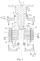
- FIG. 1 is a vertical cross-sectional view of a synchronous induction motor 1.
- the synchronous induction motor 1 uses both the induced current flowing through a secondary conductor 32 and the magnetic flux generated from permanent magnets 33 to generate a torque around a rotation axis 9.
- This synchronous induction motor 1 is used, for example, to rotate a fan of an indoor air conditioner in an electric train. It is possible for synchronous induction motors which are used for other applications to adopt the same structure. For example, synchronous induction motors having the same structure may be used in a car, consumer electronics, office automation equipment, medical equipment, tools, large industrial facilities, and others, to generate various drive force.
- the synchronous induction motor 1 includes a stationary portion 2, a rotary portion 3 and a bearing mechanism 4.
- the stationary portion 2 is fixed to a frame of an air conditioner.
- the rotary portion 3 having its center on the rotation axis 9 is rotated.
- the bearing mechanism 4 is interposed between the stationary portion 2 and the rotary portion 3, and rotatably supports the rotary portion 3.
- the stationary portion 2 includes a shaft 21 and a stator 22.
- the shaft 21 is a columnar member which extends in the axial direction on a radially inner side of the stator 22.
- the shaft 21 is made of, for example, metal such as stainless steel, or the like.
- An outer diameter of the shaft 21 decreases stepwise from an upper end toward a lower end thereof. That is, the shaft 21 includes a plurality of shaft stepped portions 210 of which outer diameter decreases stepwise from the upper end toward the lower end thereof.
- the stator 22 is an armature which generates magnetic flux in response to a drive current.
- the stator 22 includes a stator core 51 and a plurality of coils 52.
- the stator core 51 is made of, for example, a laminated steel plate in which electromagnetic steel plates made of magnetic material are stacked in the axial direction.
- the stator core 51 includes an annular core back 511 and a plurality of teeth 512 which protrude from the core back 511 toward a radially outer side.
- the core back 511 is fixed to an outer circumferential surface of the shaft 21.
- the plurality of coils 52 are formed of conductive wires wound around the teeth 512.
- winding the conductive wires may be performed by using a so-called “concentrated winding,” in which the individual conductive wire is wound around each of the teeth 512. It may also be performed by using a so-called “distributed winding", in which the individual conductive wire is wound around over two or more teeth.
- the rotary portion 3 includes a rotor core 31, the secondary conductor 32, the plurality of permanent magnets 33, a first rotor yoke 34 and a second rotor yoke 35.
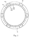
- FIG. 2 is a top view of the rotor core 31, the secondary conductor 32 and the plurality of permanent magnets 33.
- FIG. 3 is a cross-sectional view of the rotor core 31. Further, the vertical cross-sectional view of FIG. 1 corresponds to the cross-sectional view taken along the X-O-Y line in FIG. 2 .
- the rotor core 31 is an annular member located on a radially outer side of the stator 22.
- the stator core 51 is made of, for example, a laminated steel plate in which electromagnetic steel plates made of magnetic material are stacked in the axial direction.
- a load 8 such as an impeller which generates air current, may be attached to a radially outer side of the rotor core 31.
- the rotor core 31 includes a plurality of secondary conductor slots 311 and a plurality of magnet slots 312. The plurality of secondary conductor slots 311 and the plurality of magnet slots 312 respectively penetrate through the rotor core 31 in the axial direction.
- the plurality of secondary conductor slots 311 are provided in a vicinity of an inner circumferential portion of the rotor core 31 and arranged at substantially identical intervals in the circumferential direction.
- the plurality of magnet slots 312 are provided on a radially outer side than the secondary conductor slots 311 and arranged at substantially identical intervals in the circumferential direction. In this embodiment, there are more numbers of secondary conductor slots 311 than the numbers of magnet slots 312.
- the secondary conductor 32 is a conductor which serves as a path of induced current when the synchronous induction motor 1 is driven.
- the secondary conductor 32 includes a plurality of conductor bars 60, a first end ring 61 and a second end ring 62.
- the plurality of conductor bars 60 respectively extend in the axial direction within the secondary conductor slots 311.
- the first end ring 61 is provided on an upper end surface of the rotor core 31 and connects upper end portions of the plurality of conductor bars 60 in an annular shape.
- the second end ring 62 is provided on a lower end surface of the rotor core 31 and connects lower end portions of the plurality of conductor bars 60 in the annular shape.
- the secondary conductor 32 is made of a nonmagnetic conductive material.
- the secondary conductor 32 is formed as a single connected body having the plurality of conductor bars 60, the first end ring 61 and the second end ring 62, which is formed by aluminum casting.
- the secondary conductor 32 may be formed by any other manufacturing methods other than casting. Further, a material other than aluminum may be used for the secondary conductor 32.
- the secondary conductor 32 may be formed by combining a plurality of members.
- the plurality of permanent magnets 33 are respectively inserted into the magnet slots 312 and concurrently fixed to the rotor core 31 by an adhesive.
- An N pole and an S pole are respectively magnetized on both circumferential end surfaces of the permanent magnets 33.
- the adjacent permanent magnets 33 are provided such that same poles of respective permanent magnets face each other in the circumferential direction. Accordingly, by the magnetic flux of the permanent magnets 33, the N pole and the S pole appear alternately in the circumferential direction on the inner circumferential surface of the rotor core 31.
- the first rotor yoke 34 is an annular member provided at an upper side of the rotor core 31.
- the first rotor yoke 34 has a first plate portion 341 and a first cylindrical portion 342.
- the first plate portion 341 expands in a disc shape on an upper side of the stator 22 and the rotor core 31.
- the first cylindrical portion 342 extends from an end portion on the radially outer side of the first plate portion 341 toward a lower side.
- the first rotor yoke 34 has a first rotor yoke stepped portion 343 at a lower end portion of the first cylindrical portion 342.
- the first rotor yoke stepped portion 343 is an annular notched portion which contacts the corner portion of the boundary between the outer circumferential surface and the upper end surface of the rotor core 31.
- the two surfaces that form the first rotor yoke stepped portion 343 respectively contact the upper end portion of the outer circumferential surface of the rotor core 31 and the outer edge portion of the upper end surface of the rotor core 31.
- the second rotor yoke 35 is an annular member provided at a lower side of the rotor core 31.
- the second rotor yoke 35 has a second plate portion 351 and a second cylindrical portion 352.
- the second plate portion 351 expands in a disc shape on a lower side of the stator 22 and the rotor core 31.
- the second cylindrical portion 352 extends from an end portion on the radially outer side of the second plate portion 351 toward an upper side.
- the second rotor yoke 35 has a second rotor yoke stepped portion 353 at an upper end portion of the second cylindrical portion 352.
- the second rotor yoke stepped portion 353 is an annular notched portion which contacts the corner portion of the boundary between the outer circumferential surface and the lower end surface of the rotor core 31.
- the two surfaces that form the second rotor yoke stepped portion 353 respectively contact the lower end portion of the outer circumferential surface of the rotor core 31 and the outer edge portion of the lower end surface of the rotor core 31.
- the bearing mechanism 4 has a first bearing 41 and a second bearing 42.
- the first bearing 41 is provided at an upper side than the stator 22.
- the second bearing 42 is provided at a lower side than the stator 22.
- a ball bearing having a plurality of spherical bodies between an outer ring and an inner ring is used as the first bearing 41 and the second bearing 42.
- the outer ring of the first bearing 41 is fixed to an inner circumferential portion of the first plate portion 341 of the first rotor yoke 34.
- the outer ring of the second bearing 42 is fixed to an inner circumferential portion of the second plate portion 351 of the second rotor yoke 35.
- each of the inner rings of the first bearing 41 and the second bearing 42 is fixed to an outer circumferential surface of the shaft 21.
- ball bearing instead of the ball bearing, other types of bearing such as a sliding bearing a liquid bearing, or the like, may be used.
- the first bearing 41 and the second bearing 42 are respectively provided at the upper side and the lower side of the stator 22. It is therefore possible to suppress the tilting of the rotary portion 3 with respect to the rotation axis 9 when compared to a case in which the bearing is disposed only on one of the upper side or the lower side of the stator 22. Therefore, it is possible to reduce a radial gap between the stator 22 and the rotor core 31, and moreover, to prevent the stator 22 and the rotor core 31 from contacting each other when the synchronous induction motor 1 is driven. With this, it is possible to increase the efficiency of the synchronous induction motor 1.
- FIG. 4 is a partial cross-sectional view of the rotor core 31, the secondary conductor 32 and the plurality of permanent magnets 33.
- FIG. 5 is a partial vertical cross-sectional view of the rotor core 31, the secondary conductor 32, the permanent magnets 33 and the first rotor yoke 34 taken along the O-X line shown in FIG. 2 .
- FIG. 6 is a partial vertical cross-sectional view of the rotor core 31, the secondary conductor 32 and the first rotor yoke 34 taken along the O-Y line shown in FIG. 2 .
- both end surfaces in the circumferential direction of the permanent magnets 33 become magnetic pole surfaces.
- each set of neighboring permanent magnets 33 is provided such that the same poles of the respective permanent magnets 33 face each other in the circumferential direction. Therefore, a magnetic flux of the permanent magnets 33 flows from the permanent magnets 33 to the circumferential direction, not the radial direction. For this reason, even if a radially inner side portion and a radially outer side portion of the rotor core 31 are thinner than the permanent magnets 33, magnetic saturation is unlikely to occur in the rotor core if a sufficient gap exists between each set of neighboring permanent magnets 33. Therefore, when the structure according to the present disclosure is adopted, it is possible to suppress the radial dimension of the rotor core 31, and moreover, to suppress the occurrence of magnetic saturation in the rotor core 31.
- a circumferential gap between the neighboring permanent magnets 33 is larger than a circumferential width of the permanent margent 33.
- the circumferential gap between the neighboring permanent magnets 33 may be changed depending on the magnetic characteristic and the axial length of the permanent magnets 33. Therefore, the circumferential gap between the neighboring permanent magnets 33 may be equal to or smaller than the circumferential width of each of the permanent magnets 33.
- the plurality of conductor bars 60 include a plurality of first conductor bars 601 and a plurality of second conductor bars 602.
- the plurality of first conductor bars 601 are provided on a radially inner side of the permanent magnets 33, and further, disposed to a radially overlapping position with the permanent magnets 33.
- the plurality of second conductor bars 602 are provided to a position which does not overlap with the permanent magnets 33 in the radial direction, that is, the plurality of second conductor bars are disposed to a circumferential position between the plurality of permanent magnets 33.
- the radially inner side end portions of the first conductor bars 601 and the radially inner side end portions of the second conductor bars 602 are arranged in substantially the same radial positions. Meanwhile, the radially outer side end portions of the second conductor bars 602 are provided at a radially outer side than the radially outer side end portions of the first conductor bars 601 and the radially inner side surfaces of the permanents magnets 33. Therefore, a radial dimension d1 of each of the first conductor bars 601 is shorter than a radial dimension d2 of each of the second conductor bars 602.
- the first conductor bars 601 having a smaller radial dimension than that of the second conductor bars 602 are provided at a radially overlapping position with the permanent magnets 33. Accordingly, it is possible to suppress the radial dimension of the rotor core 31. Meanwhile, the second conductor bars 602 having a larger radial dimension than that of the first conductor bars 601 are provided at a position that does not radially overlap with the permanent magnets 33. Therefore, it is possible to increase a starting torque generated by the induced current.
- the conductor bars 60 and the permanent magnets 33 are provided at positions apart from each other. Specifically, the first conductor bars 601 and the permanent magnets 33 are provided at positions spaced apart from each other in the radial direction. Further, the second conductor bars 602 and the permanent magnets 33 are provided at positions spaced apart from each other in the circumferential direction. With this, it is possible to prevent the magnetic flux generated by induced current flowing through the conductor bars 60 from being inhibited in the permanent magnets 33. Therefore, it is possible to further increase the starting torque generated by the induced current.
- the first end ring 61 is provided on the upper end surface of the rotor core 31. Upper end openings of the plurality of magnet slots 312 are not covered with the first end ring 61. That is, the first end ring 61 at least partially covers the upper end surface of the rotor core 31 except for the magnet slots 312. Accordingly, the upper end surfaces of the permanent magnets 33 are exposed through the first end ring 61.
- the second end ring 62 at least partially covers the lower end surface of the rotor core 31 except for the magnet slots 312 in the same manner as the first end ring 61. Therefore, the lower end surfaces of the permanent magnets 33 are exposed through the second end ring 62.
- the first end ring 61 includes a plurality of protrusion portions 63 protruding toward a radially outer side, in a circumferential range where the permanent magnets 33 do not exist.
- the second end ring 62 includes a plurality of protrusion portions 63 in the same manner. Each of the protrusion portions 63 expands further to a radially outer side than the radially inner side surface of the permanent magnets 33.
- a radial length of the first end ring 61 provided at a radially outer side than the secondary conductor slots 311 is referred to as "a”.
- a radial length of the first end ring 61 provided at a radially outer side than the secondary conductor slots 311 is referred to as "b”.
- a relation of "a ⁇ b" is satisfied.
- a relation of "a ⁇ b" is also satisfied in the same manner.
- the rotor core 31 includes a plurality of first caulking portions 71 and a plurality of second caulking portions 72.
- the plurality of electromagnetic steel plates are plastically deformed in the axial direction, in the first caulking portions 71 and the second caulking portions 72. As a result, the plurality of electromagnetic steel plates are fixed to each other.
- the plurality of first caulking portions 71 prevent the plurality of electromagnetic steel plates from being separated from each other in the vicinity of the outer circumferential portion of the rotor core 31.
- the first caulking portions 71 are provided at the substantial center between the neighboring permanent magnets 33 in the circumferential direction. Further, the first caulking portions 71 are provided on a radially outer side than the radially inner side surface of the permanent magnets 33. In said position, the amount of magnetic flux directed from the permanent magnets 33 to the stator 22 is small. For this reason, even if the first caulking portions 71 are provided in said position, the magnetic property is unlikely to be affected.
- the plurality of second caulking portions 72 prevent the plurality of electromagnetic steel plates from being separated from each other in the vicinity of the inner circumferential portion of the rotor core 31.
- the second caulking portions 72 are provided at the substantial center between the first conductor bars 601 and the second conductor bars 602 in the circumferential direction. Further, the second caulking portions 72 are provided on a radially inner side than the radially inner side surface of the permanent magnets 33. In said position, the amount of magnetic flux directed from the permanent magnets 33 to the stator 22 is small. For this reason, even if the first caulking portions 71 are provided in said position, the magnetic property is unlikely to be affected.
- the second caulking portions 72 may be provided between the plurality of first conductor bars 601 in the circumferential direction.
- FIG. 7 is an exploded view of the synchronous induction motor 1.
- the stator 22 having the stator core 51 and the coils 52 is prepared in advance.
- the secondary conductor 32 is casted in the rotor core 31, and each of the permanent magnets 33 is inserted into the plurality of magnet slots 312 of the rotor core 31.
- the first bearing 41, the first rotor yoke 34, and the rotor core 31 approaches the shaft 21 upwardly from a lower side, in said order.
- the stator 22 and the second bearing 42 approach the shaft 21 upwardly from the lower side, in said order.
- the second rotor yoke 35 approaches upwardly from the lower side.
- the upper end surface of the inner ring of the first bearing 41, the top surface of the core back 511 of the stator core 51 and the upper end surface of the inner ring of the second bearing 42 are respectively in contact with a surface facing the lower side of the shaft stepped portion 210.
- the three shaft stepped portions 210 of the shaft 21 thus respectively have a contact surface 211 which is in contact with the upper end surface of the inner ring of the first bearing 41; a contact surface 212 which is in contact with the top surface of the core back 511 of the stator core 51; and a contact surface 213 which is in contact with the upper end surface of the inner ring of the second bearing 42.
- Each of the contact surfaces 211, 212, 213 is an annular surface which vertically expands along the rotation axis 9. The axial positions of the first bearing 41, the stator 22 and the second bearing 42 are determined by these contact surfaces 211, 212, 213.
- the synchronous induction motor 1 is assembled having all of the first bearing 41, the first rotor yoke 34, the rotor core 31, the stator 22, the second bearing 42 and the second rotor yoke 35 approach the shaft 21 upwardly from the lower side. As a result, a workload at the time of assembling the synchronous induction motor 1 is reduced.
- the rotor core 31 is interposed between the first rotor yoke 34 and the second rotor yoke 35 in the axial direction. With this, the axial position of the rotor core 31 is determined.
- the first rotor yoke 34 includes the first rotor yoke stepped portion 343 and the second rotor yoke 35 includes the second rotor yoke stepped portion 353. Further, as described above, these stepped portions 343 and 353 are in contact with the rotor core 31. Accordingly, the first rotor yoke 34, the rotor core 31 and the second rotor yoke 35 can be fixed while the relative positions thereof are easily determined.
- first rotor yoke stepped portion 343 and the second rotor yoke stepped portion 353 are fixed to the rotor core 31 by, for example, means such as an adhesive or welding, and the like.
- the inner ring of the first bearing 41, the stator core 51 and the second bearing 42 are all in contact with a surface facing the lower side of the shaft stepped portion 210.
- the inner ring of the first bearing 41, the stator core 51 and the second bearing 42 may be in contact with the surface facing the lower side of the shaft stepped portion 210.
- the plurality of conductor bars 60 extends in the axial direction.
- the plurality of conductor bars 60 may extend obliquely relative to the axial direction.
- the cross-sectional shape of the conductor bars 60 is a substantially trapezoidal shape having round corners.
- the cross-sectional shape of the conductor bars 60 may be circular or rectangular.
- the present disclosure can be used, for example, in a synchronous induction motor.
Landscapes
- Engineering & Computer Science (AREA)
- Power Engineering (AREA)
- Permanent Magnet Type Synchronous Machine (AREA)
- Iron Core Of Rotating Electric Machines (AREA)
- Permanent Field Magnets Of Synchronous Machinery (AREA)
Applications Claiming Priority (1)
| Application Number | Priority Date | Filing Date | Title |
|---|---|---|---|
| JP2015023746A JP6474268B2 (ja) | 2015-02-10 | 2015-02-10 | 誘導同期電動機 |
Publications (1)
| Publication Number | Publication Date |
|---|---|
| EP3057208A1 true EP3057208A1 (fr) | 2016-08-17 |
Family
ID=55237573
Family Applications (1)
| Application Number | Title | Priority Date | Filing Date |
|---|---|---|---|
| EP16152947.4A Withdrawn EP3057208A1 (fr) | 2015-02-10 | 2016-01-27 | Moteur à induction synchrone |
Country Status (3)
| Country | Link |
|---|---|
| EP (1) | EP3057208A1 (fr) |
| JP (1) | JP6474268B2 (fr) |
| CN (2) | CN105871156B (fr) |
Cited By (5)
| Publication number | Priority date | Publication date | Assignee | Title |
|---|---|---|---|---|
| CN107919752A (zh) * | 2017-11-14 | 2018-04-17 | 珠海凯邦电机制造有限公司 | 电机 |
| CN107919753A (zh) * | 2017-11-14 | 2018-04-17 | 珠海凯邦电机制造有限公司 | 电机 |
| US20180205302A1 (en) * | 2017-01-19 | 2018-07-19 | Hamilton Sundstrand Corporation | Permanent magnet (pm) brushless machine with outer rotor |
| DE202018005606U1 (de) | 2018-12-04 | 2019-04-03 | Tibor Kaiser | Synchronmaschinenausrüstung mit hohem Antrieb und Selbsterregung |
| CN115580032A (zh) * | 2022-09-29 | 2023-01-06 | 中国兵器装备集团上海电控研究所 | 一种非接触式旋转传输装置 |
Families Citing this family (4)
| Publication number | Priority date | Publication date | Assignee | Title |
|---|---|---|---|---|
| JP6474268B2 (ja) * | 2015-02-10 | 2019-02-27 | 日本電産テクノモータ株式会社 | 誘導同期電動機 |
| CN106762734B (zh) * | 2016-12-21 | 2019-12-17 | 宁波江北怡和工业设计有限公司 | 一种户外恒定风风扇 |
| CN113991958A (zh) * | 2017-07-21 | 2022-01-28 | 株式会社电装 | 旋转电机 |
| CN114430218B (zh) * | 2022-01-28 | 2023-05-16 | 淄博朗达复合材料有限公司 | 转子、电机及转子的制造方法 |
Citations (4)
| Publication number | Priority date | Publication date | Assignee | Title |
|---|---|---|---|---|
| JPS56139063A (en) * | 1980-03-31 | 1981-10-30 | Shinko Electric Co Ltd | Outer rotor type motor |
| DE4418454A1 (de) * | 1994-05-26 | 1995-11-30 | Siemens Ag | Außenläufer einer Synchronmaschine |
| JP2003018776A (ja) | 2001-03-30 | 2003-01-17 | Sanyo Electric Co Ltd | 誘導同期電動機 |
| GB2392315A (en) * | 2002-05-10 | 2004-02-25 | Delta Invest Ltd | Rotor and stator for a permanent magnet motor |
Family Cites Families (13)
| Publication number | Priority date | Publication date | Assignee | Title |
|---|---|---|---|---|
| JPS4710029Y1 (fr) * | 1968-04-30 | 1972-04-14 | ||
| JPS62135562U (fr) * | 1986-11-06 | 1987-08-26 | ||
| JPH08172742A (ja) * | 1994-12-19 | 1996-07-02 | Toshiba Corp | 永久磁石界磁方式回転電機 |
| US5818137A (en) * | 1995-10-26 | 1998-10-06 | Satcon Technology, Inc. | Integrated magnetic levitation and rotation system |
| JP2001037190A (ja) * | 1999-07-23 | 2001-02-09 | Toshiba Corp | 自己始動形永久磁石付回転電機 |
| TWI288519B (en) * | 2002-03-27 | 2007-10-11 | Sanyo Electric Co | Synchronous induction motor |
| DE102005060117A1 (de) * | 2004-12-20 | 2006-07-06 | Danfoss Compressors Gmbh | Rotor mit Deckplatte zur Sicherung eines Magneten im Rotor |
| JP2008245439A (ja) * | 2007-03-28 | 2008-10-09 | Hitachi Appliances Inc | 電動機及びそれを用いた圧縮機 |
| SE534248C2 (sv) * | 2008-10-23 | 2011-06-14 | Itt Mfg Enterprises Inc | Omröraraggregat med rotor innefattande sektioner av synkron och asynkron typ |
| CN202068290U (zh) * | 2010-11-19 | 2011-12-07 | 王乃兵 | 一种异步起动永磁同步电动机转子冲片 |
| JP5919629B2 (ja) * | 2011-03-10 | 2016-05-18 | ダイキン工業株式会社 | 永久磁石回転子の製造方法 |
| CN103580428B (zh) * | 2013-11-12 | 2015-07-29 | 大连碧蓝节能环保科技有限公司 | 半磁片外转子式异步起动永磁同步电动机 |
| JP6474268B2 (ja) * | 2015-02-10 | 2019-02-27 | 日本電産テクノモータ株式会社 | 誘導同期電動機 |
-
2015
- 2015-02-10 JP JP2015023746A patent/JP6474268B2/ja not_active Expired - Fee Related
-
2016
- 2016-01-27 EP EP16152947.4A patent/EP3057208A1/fr not_active Withdrawn
- 2016-02-04 CN CN201610079571.8A patent/CN105871156B/zh not_active Expired - Fee Related
- 2016-02-04 CN CN201620113967.5U patent/CN205544853U/zh not_active Withdrawn - After Issue
Patent Citations (4)
| Publication number | Priority date | Publication date | Assignee | Title |
|---|---|---|---|---|
| JPS56139063A (en) * | 1980-03-31 | 1981-10-30 | Shinko Electric Co Ltd | Outer rotor type motor |
| DE4418454A1 (de) * | 1994-05-26 | 1995-11-30 | Siemens Ag | Außenläufer einer Synchronmaschine |
| JP2003018776A (ja) | 2001-03-30 | 2003-01-17 | Sanyo Electric Co Ltd | 誘導同期電動機 |
| GB2392315A (en) * | 2002-05-10 | 2004-02-25 | Delta Invest Ltd | Rotor and stator for a permanent magnet motor |
Cited By (6)
| Publication number | Priority date | Publication date | Assignee | Title |
|---|---|---|---|---|
| US20180205302A1 (en) * | 2017-01-19 | 2018-07-19 | Hamilton Sundstrand Corporation | Permanent magnet (pm) brushless machine with outer rotor |
| EP3352347A1 (fr) * | 2017-01-19 | 2018-07-25 | Hamilton Sundstrand Corporation | Machine sans balai à aimant permanent (pm) à rotor externe |
| CN107919752A (zh) * | 2017-11-14 | 2018-04-17 | 珠海凯邦电机制造有限公司 | 电机 |
| CN107919753A (zh) * | 2017-11-14 | 2018-04-17 | 珠海凯邦电机制造有限公司 | 电机 |
| DE202018005606U1 (de) | 2018-12-04 | 2019-04-03 | Tibor Kaiser | Synchronmaschinenausrüstung mit hohem Antrieb und Selbsterregung |
| CN115580032A (zh) * | 2022-09-29 | 2023-01-06 | 中国兵器装备集团上海电控研究所 | 一种非接触式旋转传输装置 |
Also Published As
| Publication number | Publication date |
|---|---|
| JP2016149816A (ja) | 2016-08-18 |
| CN105871156A (zh) | 2016-08-17 |
| JP6474268B2 (ja) | 2019-02-27 |
| CN105871156B (zh) | 2019-10-11 |
| CN205544853U (zh) | 2016-08-31 |
Similar Documents
| Publication | Publication Date | Title |
|---|---|---|
| EP3057208A1 (fr) | Moteur à induction synchrone | |
| CN202940656U (zh) | 马达 | |
| CN108370178B (zh) | 轴向间隙型旋转电机及其制造方法 | |
| JP6196864B2 (ja) | 永久磁石回転電機 | |
| JP2012186889A (ja) | 回転電機 | |
| WO2014188628A1 (fr) | Rotor et moteur | |
| JP2007074776A (ja) | 回転電機 | |
| JP3207654U (ja) | 単相永久磁石モータ | |
| JP2017229136A (ja) | アキシャルギャップモータ用ロータ及びアキシャルギャップモータ | |
| US20150380995A1 (en) | Embedded permanent magnet type rotating electric machine | |
| JP2018082600A (ja) | ダブルロータ型の回転電機 | |
| JP2014045634A (ja) | ロータ及びこのロータを備える回転電機 | |
| JP2014236576A (ja) | インナーロータ型モータ | |
| CN203896058U (zh) | 永磁式旋转电机及电梯驱动提升机 | |
| JP2014064471A (ja) | 回転電機 | |
| JPWO2019008930A1 (ja) | ステータおよびモータ | |
| JP6508863B1 (ja) | アウターロータ型モータおよび電気自動車 | |
| JP2019161828A (ja) | 回転電機 | |
| JP2016129447A (ja) | 回転電機 | |
| JP2005269693A (ja) | 永久磁石モータ | |
| JP2017163675A (ja) | 固定子鉄心、固定子及び回転電機 | |
| JP6745212B2 (ja) | 回転子およびリラクタンス回転電機 | |
| JP4556408B2 (ja) | クローポール形回転機 | |
| JP2009142024A (ja) | リラクタンスモータ | |
| CN107873116B (zh) | 单极复励型异步电机 |
Legal Events
| Date | Code | Title | Description |
|---|---|---|---|
| PUAI | Public reference made under article 153(3) epc to a published international application that has entered the european phase |
Free format text: ORIGINAL CODE: 0009012 |
|
| AK | Designated contracting states |
Kind code of ref document: A1 Designated state(s): AL AT BE BG CH CY CZ DE DK EE ES FI FR GB GR HR HU IE IS IT LI LT LU LV MC MK MT NL NO PL PT RO RS SE SI SK SM TR |
|
| AX | Request for extension of the european patent |
Extension state: BA ME |
|
| 17P | Request for examination filed |
Effective date: 20170215 |
|
| RBV | Designated contracting states (corrected) |
Designated state(s): AL AT BE BG CH CY CZ DE DK EE ES FI FR GB GR HR HU IE IS IT LI LT LU LV MC MK MT NL NO PL PT RO RS SE SI SK SM TR |
|
| RIC1 | Information provided on ipc code assigned before grant |
Ipc: H02K 1/27 20060101ALI20180206BHEP Ipc: H02K 7/08 20060101ALI20180206BHEP Ipc: H02K 1/26 20060101ALN20180206BHEP Ipc: H02K 21/46 20060101AFI20180206BHEP |
|
| GRAP | Despatch of communication of intention to grant a patent |
Free format text: ORIGINAL CODE: EPIDOSNIGR1 |
|
| RIC1 | Information provided on ipc code assigned before grant |
Ipc: H02K 7/08 20060101ALI20180302BHEP Ipc: H02K 1/27 20060101ALI20180302BHEP Ipc: H02K 21/46 20060101AFI20180302BHEP Ipc: H02K 1/26 20060101ALN20180302BHEP |
|
| INTG | Intention to grant announced |
Effective date: 20180319 |
|
| STAA | Information on the status of an ep patent application or granted ep patent |
Free format text: STATUS: THE APPLICATION IS DEEMED TO BE WITHDRAWN |
|
| 18D | Application deemed to be withdrawn |
Effective date: 20180731 |