EP3323982B1 - Profil aérodynamique, moteur à turbine à gaz ayant un tel profil et procédé de fabrication d'un profil aérodynamique - Google Patents
Profil aérodynamique, moteur à turbine à gaz ayant un tel profil et procédé de fabrication d'un profil aérodynamique Download PDFInfo
- Publication number
- EP3323982B1 EP3323982B1 EP17202239.4A EP17202239A EP3323982B1 EP 3323982 B1 EP3323982 B1 EP 3323982B1 EP 17202239 A EP17202239 A EP 17202239A EP 3323982 B1 EP3323982 B1 EP 3323982B1
- Authority
- EP
- European Patent Office
- Prior art keywords
- airfoil
- panel
- connector
- core structure
- section
- Prior art date
- Legal status (The legal status is an assumption and is not a legal conclusion. Google has not performed a legal analysis and makes no representation as to the accuracy of the status listed.)
- Active
Links
Images
Classifications
-
- F—MECHANICAL ENGINEERING; LIGHTING; HEATING; WEAPONS; BLASTING
- F01—MACHINES OR ENGINES IN GENERAL; ENGINE PLANTS IN GENERAL; STEAM ENGINES
- F01D—NON-POSITIVE DISPLACEMENT MACHINES OR ENGINES, e.g. STEAM TURBINES
- F01D5/00—Blades; Blade-carrying members; Heating, heat-insulating, cooling or antivibration means on the blades or the members
- F01D5/12—Blades
- F01D5/14—Form or construction
- F01D5/147—Construction, i.e. structural features, e.g. of weight-saving hollow blades
-
- F—MECHANICAL ENGINEERING; LIGHTING; HEATING; WEAPONS; BLASTING
- F01—MACHINES OR ENGINES IN GENERAL; ENGINE PLANTS IN GENERAL; STEAM ENGINES
- F01D—NON-POSITIVE DISPLACEMENT MACHINES OR ENGINES, e.g. STEAM TURBINES
- F01D25/00—Component parts, details, or accessories, not provided for in, or of interest apart from, other groups
- F01D25/08—Cooling; Heating; Heat-insulation
- F01D25/12—Cooling
-
- F—MECHANICAL ENGINEERING; LIGHTING; HEATING; WEAPONS; BLASTING
- F01—MACHINES OR ENGINES IN GENERAL; ENGINE PLANTS IN GENERAL; STEAM ENGINES
- F01D—NON-POSITIVE DISPLACEMENT MACHINES OR ENGINES, e.g. STEAM TURBINES
- F01D5/00—Blades; Blade-carrying members; Heating, heat-insulating, cooling or antivibration means on the blades or the members
- F01D5/12—Blades
- F01D5/14—Form or construction
- F01D5/18—Hollow blades, i.e. blades with cooling or heating channels or cavities; Heating, heat-insulating or cooling means on blades
-
- F—MECHANICAL ENGINEERING; LIGHTING; HEATING; WEAPONS; BLASTING
- F01—MACHINES OR ENGINES IN GENERAL; ENGINE PLANTS IN GENERAL; STEAM ENGINES
- F01D—NON-POSITIVE DISPLACEMENT MACHINES OR ENGINES, e.g. STEAM TURBINES
- F01D5/00—Blades; Blade-carrying members; Heating, heat-insulating, cooling or antivibration means on the blades or the members
- F01D5/12—Blades
- F01D5/14—Form or construction
- F01D5/18—Hollow blades, i.e. blades with cooling or heating channels or cavities; Heating, heat-insulating or cooling means on blades
- F01D5/187—Convection cooling
- F01D5/188—Convection cooling with an insert in the blade cavity to guide the cooling fluid, e.g. forming a separation wall
-
- F—MECHANICAL ENGINEERING; LIGHTING; HEATING; WEAPONS; BLASTING
- F01—MACHINES OR ENGINES IN GENERAL; ENGINE PLANTS IN GENERAL; STEAM ENGINES
- F01D—NON-POSITIVE DISPLACEMENT MACHINES OR ENGINES, e.g. STEAM TURBINES
- F01D5/00—Blades; Blade-carrying members; Heating, heat-insulating, cooling or antivibration means on the blades or the members
- F01D5/12—Blades
- F01D5/28—Selecting particular materials; Particular measures relating thereto; Measures against erosion or corrosion
- F01D5/282—Selecting composite materials, e.g. blades with reinforcing filaments
-
- F—MECHANICAL ENGINEERING; LIGHTING; HEATING; WEAPONS; BLASTING
- F01—MACHINES OR ENGINES IN GENERAL; ENGINE PLANTS IN GENERAL; STEAM ENGINES
- F01D—NON-POSITIVE DISPLACEMENT MACHINES OR ENGINES, e.g. STEAM TURBINES
- F01D5/00—Blades; Blade-carrying members; Heating, heat-insulating, cooling or antivibration means on the blades or the members
- F01D5/12—Blades
- F01D5/28—Selecting particular materials; Particular measures relating thereto; Measures against erosion or corrosion
- F01D5/284—Selection of ceramic materials
-
- F—MECHANICAL ENGINEERING; LIGHTING; HEATING; WEAPONS; BLASTING
- F01—MACHINES OR ENGINES IN GENERAL; ENGINE PLANTS IN GENERAL; STEAM ENGINES
- F01D—NON-POSITIVE DISPLACEMENT MACHINES OR ENGINES, e.g. STEAM TURBINES
- F01D5/00—Blades; Blade-carrying members; Heating, heat-insulating, cooling or antivibration means on the blades or the members
- F01D5/12—Blades
- F01D5/28—Selecting particular materials; Particular measures relating thereto; Measures against erosion or corrosion
- F01D5/288—Protective coatings for blades
-
- F—MECHANICAL ENGINEERING; LIGHTING; HEATING; WEAPONS; BLASTING
- F01—MACHINES OR ENGINES IN GENERAL; ENGINE PLANTS IN GENERAL; STEAM ENGINES
- F01D—NON-POSITIVE DISPLACEMENT MACHINES OR ENGINES, e.g. STEAM TURBINES
- F01D9/00—Stators
- F01D9/02—Nozzles; Nozzle boxes; Stator blades; Guide conduits, e.g. individual nozzles
- F01D9/04—Nozzles; Nozzle boxes; Stator blades; Guide conduits, e.g. individual nozzles forming ring or sector
- F01D9/041—Nozzles; Nozzle boxes; Stator blades; Guide conduits, e.g. individual nozzles forming ring or sector using blades
-
- F—MECHANICAL ENGINEERING; LIGHTING; HEATING; WEAPONS; BLASTING
- F02—COMBUSTION ENGINES; HOT-GAS OR COMBUSTION-PRODUCT ENGINE PLANTS
- F02C—GAS-TURBINE PLANTS; AIR INTAKES FOR JET-PROPULSION PLANTS; CONTROLLING FUEL SUPPLY IN AIR-BREATHING JET-PROPULSION PLANTS
- F02C7/00—Features, components parts, details or accessories, not provided for in, or of interest apart form groups F02C1/00 - F02C6/00; Air intakes for jet-propulsion plants
- F02C7/12—Cooling of plants
-
- F—MECHANICAL ENGINEERING; LIGHTING; HEATING; WEAPONS; BLASTING
- F05—INDEXING SCHEMES RELATING TO ENGINES OR PUMPS IN VARIOUS SUBCLASSES OF CLASSES F01-F04
- F05D—INDEXING SCHEME FOR ASPECTS RELATING TO NON-POSITIVE-DISPLACEMENT MACHINES OR ENGINES, GAS-TURBINES OR JET-PROPULSION PLANTS
- F05D2220/00—Application
- F05D2220/30—Application in turbines
- F05D2220/32—Application in turbines in gas turbines
-
- F—MECHANICAL ENGINEERING; LIGHTING; HEATING; WEAPONS; BLASTING
- F05—INDEXING SCHEMES RELATING TO ENGINES OR PUMPS IN VARIOUS SUBCLASSES OF CLASSES F01-F04
- F05D—INDEXING SCHEME FOR ASPECTS RELATING TO NON-POSITIVE-DISPLACEMENT MACHINES OR ENGINES, GAS-TURBINES OR JET-PROPULSION PLANTS
- F05D2230/00—Manufacture
- F05D2230/60—Assembly methods
-
- F—MECHANICAL ENGINEERING; LIGHTING; HEATING; WEAPONS; BLASTING
- F05—INDEXING SCHEMES RELATING TO ENGINES OR PUMPS IN VARIOUS SUBCLASSES OF CLASSES F01-F04
- F05D—INDEXING SCHEME FOR ASPECTS RELATING TO NON-POSITIVE-DISPLACEMENT MACHINES OR ENGINES, GAS-TURBINES OR JET-PROPULSION PLANTS
- F05D2230/00—Manufacture
- F05D2230/90—Coating; Surface treatment
-
- F—MECHANICAL ENGINEERING; LIGHTING; HEATING; WEAPONS; BLASTING
- F05—INDEXING SCHEMES RELATING TO ENGINES OR PUMPS IN VARIOUS SUBCLASSES OF CLASSES F01-F04
- F05D—INDEXING SCHEME FOR ASPECTS RELATING TO NON-POSITIVE-DISPLACEMENT MACHINES OR ENGINES, GAS-TURBINES OR JET-PROPULSION PLANTS
- F05D2240/00—Components
- F05D2240/10—Stators
- F05D2240/12—Fluid guiding means, e.g. vanes
-
- F—MECHANICAL ENGINEERING; LIGHTING; HEATING; WEAPONS; BLASTING
- F05—INDEXING SCHEMES RELATING TO ENGINES OR PUMPS IN VARIOUS SUBCLASSES OF CLASSES F01-F04
- F05D—INDEXING SCHEME FOR ASPECTS RELATING TO NON-POSITIVE-DISPLACEMENT MACHINES OR ENGINES, GAS-TURBINES OR JET-PROPULSION PLANTS
- F05D2240/00—Components
- F05D2240/20—Rotors
- F05D2240/30—Characteristics of rotor blades, i.e. of any element transforming dynamic fluid energy to or from rotational energy and being attached to a rotor
-
- F—MECHANICAL ENGINEERING; LIGHTING; HEATING; WEAPONS; BLASTING
- F05—INDEXING SCHEMES RELATING TO ENGINES OR PUMPS IN VARIOUS SUBCLASSES OF CLASSES F01-F04
- F05D—INDEXING SCHEME FOR ASPECTS RELATING TO NON-POSITIVE-DISPLACEMENT MACHINES OR ENGINES, GAS-TURBINES OR JET-PROPULSION PLANTS
- F05D2260/00—Function
- F05D2260/20—Heat transfer, e.g. cooling
- F05D2260/202—Heat transfer, e.g. cooling by film cooling
-
- F—MECHANICAL ENGINEERING; LIGHTING; HEATING; WEAPONS; BLASTING
- F05—INDEXING SCHEMES RELATING TO ENGINES OR PUMPS IN VARIOUS SUBCLASSES OF CLASSES F01-F04
- F05D—INDEXING SCHEME FOR ASPECTS RELATING TO NON-POSITIVE-DISPLACEMENT MACHINES OR ENGINES, GAS-TURBINES OR JET-PROPULSION PLANTS
- F05D2300/00—Materials; Properties thereof
- F05D2300/20—Oxide or non-oxide ceramics
-
- Y—GENERAL TAGGING OF NEW TECHNOLOGICAL DEVELOPMENTS; GENERAL TAGGING OF CROSS-SECTIONAL TECHNOLOGIES SPANNING OVER SEVERAL SECTIONS OF THE IPC; TECHNICAL SUBJECTS COVERED BY FORMER USPC CROSS-REFERENCE ART COLLECTIONS [XRACs] AND DIGESTS
- Y02—TECHNOLOGIES OR APPLICATIONS FOR MITIGATION OR ADAPTATION AGAINST CLIMATE CHANGE
- Y02T—CLIMATE CHANGE MITIGATION TECHNOLOGIES RELATED TO TRANSPORTATION
- Y02T50/00—Aeronautics or air transport
- Y02T50/60—Efficient propulsion technologies, e.g. for aircraft
Definitions
- the present disclosure relates to airfoils for gas turbine engines.
- a gas turbine engine typically includes a fan section, a compressor section, a combustor section and a turbine section. Air entering the compressor section is compressed and delivered into the combustion section where it is mixed with fuel and ignited to generate a high-speed exhaust gas flow. The high-speed exhaust gas flow expands through the turbine section to drive the compressor and the fan section.
- the compressor section typically includes low and high pressure compressors, and the turbine section includes low and high pressure turbines.
- the high pressure turbine drives the high pressure compressor through an outer shaft to form a high spool
- the low pressure turbine drives the low pressure compressor through an inner shaft to form a low spool.
- the fan section may also be driven by the low inner shaft.
- a direct drive gas turbine engine includes a fan section driven by the low spool such that the low pressure compressor, low pressure turbine and fan section rotate at a common speed in a common direction.
- a speed reduction device such as an epicyclical gear assembly, may be utilized to drive the fan section such that the fan section may rotate at a speed different than the turbine section.
- a shaft driven by one of the turbine sections provides an input to the epicyclical gear assembly that drives the fan section at a reduced speed.
- the present invention provides an airfoil according to claim 1.
- the panel includes a first connector and the core structure includes a second connector that is interlocked with the first connector in a joint that secures the panel to the core structure.
- one of the first connector and the second connector includes a dovetail and the other of the first connector and the second connector includes a doveslot.
- the panel includes an internal passage.
- the panel is ceramic and the core structure is metal.
- the core structure includes an exterior wall that forms a portion of the airfoil profile.
- the exterior wall forms a trailing end of the airfoil profile.
- the panel includes an internal passage, an external wall that borders the internal passage, and a cooling hole that extends through the external wall and that opens to the internal passage.
- the panel and the additional panel have different compositions.
- the panel is located adjacent the additional panel.
- the panel and the additional panel define a cooling hole at an edge interface there between.
- the panel and the additional panel together form at least a portion of a leading end of the airfoil profile.
- the core structure includes an internal passage.
- the core structure also includes a geometrically segmented coating section.
- the geometrically segmented coating section includes a wall that has an outer side.
- the outer side includes an array of cells, and a coating is disposed in the array of cells.
- the present invention provides a gas turbine engine according to claim 13.
- the present invention provides a method of assembling an airfoil according to claim 14.
- the panel includes a first connector and the core structure includes a second connector, and the securing includes mating the first connector and the second connector together.
- one of the first connector and the second connector includes a dovetail and the other of the first connector and the second connector includes a doveslot.
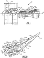
- FIG. 1 schematically illustrates a gas turbine engine 20.
- the gas turbine engine 20 is disclosed herein as a two-spool turbofan that generally incorporates a fan section 22, a compressor section 24, a combustor section 26 and a turbine section 28.
- Alternative engine designs can include an augmentor section (not shown) among other systems or features.
- the fan section 22 drives air along a bypass flow path B in a bypass duct defined within a nacelle 15, while the compressor section 24 drives air along a core flow path C for compression and communication into the combustor section 26 then expansion through the turbine section 28.
- the examples herein are not limited to use with two-spool turbofans and may be applied to other types of turbomachinery, including direct drive engine architectures, three-spool engine architectures, and ground-based turbines.
- the engine 20 generally includes a low speed spool 30 and a high speed spool 32 mounted for rotation about an engine central longitudinal axis A relative to an engine static structure 36 via several bearing systems 38. It should be understood that various bearing systems 38 at various locations may alternatively or additionally be provided, and the location of bearing systems 38 may be varied as appropriate to the application.
- the low speed spool 30 generally includes an inner shaft 40 that interconnects a fan 42, a first (or low) pressure compressor 44 and a first (or low) pressure turbine 46.
- the inner shaft 40 may be connected to the fan 42 through a speed change mechanism, which in exemplary gas turbine engine 20 is illustrated as a geared architecture 48, to drive the fan 42 at a lower speed than the low speed spool 30.
- the high speed spool 32 includes an outer shaft 50 that interconnects a second (or high) pressure compressor 52 and a second (or high) pressure turbine 54.
- a combustor 56 is arranged between the high pressure compressor 52 and the high pressure turbine 54.
- a mid-turbine frame 57 of the engine static structure 36, if included, is arranged generally between the high pressure turbine 54 and the low pressure turbine 46.
- the mid-turbine frame 57 further supports the bearing systems 38 in the turbine section 28.
- the inner shaft 40 and the outer shaft 50 are concentric and rotate via bearing systems 38 about the engine central longitudinal axis A, which is collinear with their longitudinal axes.
- the core airflow is compressed by the low pressure compressor 44 then the high pressure compressor 52, mixed and burned with fuel in the combustor 56, then expanded through the high pressure turbine 54 and low pressure turbine 46.
- the mid-turbine frame 57 includes airfoils 59 which are in the core airflow path C.
- the turbines 46, 54 rotationally drive the respective low speed spool 30 and high speed spool 32 in response to the expansion.
- gear system 48 may be located aft of combustor section 26 or even aft of turbine section 28, and fan section 22 may be positioned forward or aft of the location of gear system 48.
- the engine 20 in one example is a high-bypass geared aircraft engine.
- the engine 20 bypass ratio is greater than about six, with an example embodiment being greater than about ten
- the geared architecture 48 is an epicyclic gear train, such as a planetary gear system or other gear system, with a gear reduction ratio of greater than about 2.3 and the low pressure turbine 46 has a pressure ratio that is greater than about five.
- the engine 20 bypass ratio is greater than about ten
- the fan diameter is significantly larger than that of the low pressure compressor 44
- the low pressure turbine 46 has a pressure ratio that is greater than about five.
- Low pressure turbine 46 pressure ratio is pressure measured prior to inlet of low pressure turbine 46 as related to the pressure at the outlet of the low pressure turbine 46 prior to an exhaust nozzle.
- the geared architecture 48 may be an epicycle gear train, such as a planetary gear system or other gear system, with a gear reduction ratio of greater than about 2.3:1. It should be understood, however, that the above parameters are only exemplary of one embodiment of a geared architecture engine and that the present invention is applicable to other gas turbine engines, including direct drive turbofans and gas turbines with multiple bypass streams.
- the fan section 22 of the engine 20 may be designed for a particular flight condition -- typically cruise at about 0.8 Mach and about 35,000 feet (10.7 km).
- the flight condition of 0.8 Mach and 35,000 ft (10.7 km), with the engine at its best fuel consumption - also known as "bucket cruise Thrust Specific Fuel Consumption ('TSFC')" - is the industry standard parameter of lbm of fuel being burned divided by lbf of thrust the engine produces at that minimum point.
- “Low fan pressure ratio” is the pressure ratio across the fan blade alone, without a Fan Exit Guide Vane (“FEGV”) system.
- the low fan pressure ratio as disclosed herein according to one non-limiting embodiment is less than about 1.45.
- the "Low corrected fan tip speed” as disclosed herein according to one non-limiting embodiment is less than about 1150 ft / second (351 m/s).
- Figure 2A illustrates one such component, namely an airfoil 60.
- the airfoil 60 can be a turbine vane, as represented at 60a in Figure 1 , or a compressor vane, as represented at 60b in Figure 1 .
- the examples herein are described in the context of a vane, this disclosure is not limited to vanes, and the examples may also be applicable to blades or other airfoils that are exposed to high temperatures.
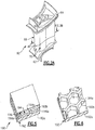
- the airfoil 60 includes inner and outer platforms 62/64 and an airfoil section 66 that extends radially between the inner and outer platforms 62/64.
- the airfoil section 66 may be hollow and can include one or more internal passages 68 ( Figure 2B ).
- a passage can include a cavity, a channel, or the like.
- the airfoil section 66 defines an airfoil profile, AP, which is the peripheral shape of the airfoil section 66 when viewed in a radial direction.
- the airfoil profile has a wing-like shape that provides a reaction force via Bernoulli's principle with regard to flow over the airfoil section 66.
- the airfoil profile generally includes a leading end (LE), a trailing end (TE), a pressure side (PS), and a suction side (SS).
- the leading end (LE) is the region of the airfoil profile (AP) that includes a leading edge of the airfoil profile (AP)
- the trailing end (TE) is the region of the airfoil profile that includes a trailing edge.
- the leading edge may be the portion of the airfoil profile (AP) that first contacts air or the foremost edge of the airfoil profile (AP).
- the trailing edge may be the portion of the airfoil profile (AP) that last contacts air or the aftmost edge of the airfoil profile (AP).
- the leading edge may shift, depending on the orientation of the vane.
- the airfoil section 66 includes one or more distinct panels 70, which are also individually designated 70a, 70b, 70c, and 70d (collectively "panels 70"). Each of the panels 70 forms a portion of the airfoil profile.
- the panels 70 are each secured to a core structure 72, which positions and mechanically supports the panels 70., The panels 70 are removably secured to the core structure 72 such that any of individual panels 70a, 70b, 70c, and 70d can be removed and replaced if needed.
- the airfoil section 66 includes four panels 70 secured to the core structure 72. As will be appreciated, fewer panels 70 or more panels 70 could be used in modified embodiments. Most typically, the core structure 72, provided as a single piece or single monolithic piece, supports multiple panels 70, such as at least one panel but typically not more than nine panels.
- Each of the four panels 70 defines a different portion of the airfoil profile.
- panel 70a defines a portion of the leading end LE (toward the suction side)
- panel 70b defines a central portion of the leading end LE
- panel 70c defines a portion of the leading end LE (toward the pressure side)
- panel 70d defines a portion of the pressure side PS.
- the leading end LE is therefore trifurcated.
- division of the leading end LE of the airfoil profile into two or more panels 70 enables the properties of leading end LE of the airfoil profile to be tailored to accommodate different incidence angles at different variable vane positions.
- the cooling air can be fed independently to the panels 70 at the pressure side of the leading end (LE), the leading edge of the leading end (LE), and the suction side of the leading end (LE) to ensure that no one panel 70 is starved of cooling air as the incidence angle experienced by the airfoil 60 varies, thus changing the location of the stagnation pressure region and the overall airfoil pressure distribution.
- the panels 70 include film cooling holes, the cooling hole patterns in each panel can be tailored to cover the incidence angle range and ensure adequate film cooling coverage of the panel 70 and downstream portions of the panel.
- the suction side SS may have relatively severe temperature conditions on the airfoil profile.
- the leading end LE may have severe temperature and erosion conditions.
- the panels 70a, 70b, 70c, and 70d may be individually adapted for the particular environmental conditions at the particular panel location on the airfoil profile.
- the material of which each panel 70 is formed is selected to enhance the performance of the panel 70 for the particular panel location.
- one or more of the panels 70 is ceramic, which has high temperature resistance and corrosion resistance in comparison to nickel alloys.
- a ceramic material is a compound of metallic or metalloid elements bonded with nonmetallic elements or metalloid elements primarily in ionic or covalent bonds.
- Example ceramic materials may include, but are not limited to, oxides, carbides, nitrides, borides, silicides, and combinations thereof.
- one or more of the panels 70 are formed of a monolithic ceramic or a ceramic matrix composite (CMC).
- a monolithic ceramic is composed of a single, homogenous ceramic material.
- a composite is composed of two or more materials that are individually easily distinguishable.
- a CMC has a reinforcement phase, such as ceramic or carbon fibers, dispersed in a ceramic matrix formed of oxides, carbides, nitrides, borides, silicides, or combinations thereof.
- the monolithic ceramic or CMC panels may be coated with an environmental barrier coating and / or a thermal barrier coating.
- the core structure 72 may be formed of a ceramic or of a metal alloy.
- Metal alloys provide a good combination of strength and durability.
- Example alloys may include, but are not limited to, nickel alloys, cobalt alloys, a nickel alloy coated with cobalt or cobalt alloy, or non-nickel alloys that do not substantially react with ceramic.
- the core structure 72 in the illustrated example generally includes several portions, defined by the different functions served.
- the forward portion of the core structure 72 serves to support and position the panels 70, while the aft portion serves to define a portion of the airfoil profile.
- the aft portion of the core structure 72 may include exterior wall portions 72a that form a portion of the airfoil profile.
- the exterior wall portions 72a form the trailing end TE of the airfoil profile, which may have less severe environmental exposure conditions which the alloy of the core structure 72 can withstand.
- panels 70 can instead be used to form the trailing end of the airfoil profile or the exterior wall portion 72a can be coated with a thermal and/or environmental barrier ceramic coating.
- the ceramic may include or may be oxides, carbides, nitrides, borides, silicides, or combinations thereof.
- the ceramic may be or may include yttria stabilized with zirconia, hafnia, and/or gadolinia, gadolinia zirconate, molybdate, alumina, or combinations thereof.
- each of the panels 70 is secured to the core structure 72 in a respective joint 74.
- the joints 74 are interlocking joints.
- each panel 70 includes a first connector 74a and the core structure 72 includes a plurality of second connectors 74b.
- Each second connector 74b on the core structure 72 interlocks with a corresponding one of the first connectors 74a on the panels 70 to secure the panels 70 and the core structure 72 together in a "jigsaw puzzle" arrangement.
- the core structure 72 has a shape that geometrically compliments the geometry of the panels 70 such that, when assembled together, the panels 70 and core structure 72 form the airfoil profile. Most typically, the panels 70 and core structure 72 will form the complete airfoil profile.
- the type of interlocking joint may be, but is not limited to, a dovetail type joint.
- one of the first connector 74a or the second connector 74b includes a dovetail 74a-1 and the other of the first connector 74a or the second connector 74b includes a doveslot 74b-1.
- Dovetails generally are tapered tabs and doveslots are generally tapered slots that correspond in geometry to the tapered tab such that the tab and slot interlock.
- the panels 70 each include dovetails and the core structure 72 includes doveslots.
- the dovetails may be on the core structure 72 and the doveslots may be on the panels 70; or the panels 70 and core structure 72 may include a mix of dovetails and doveslots.
- each of the panels 70 is hollow and defines one of the internal passages 68.
- the passages 68 permit cooling bleed air to be provided into or through the panels 70.
- the passages 68 may be sealed to provide an insulation volume.
- the panel 70b includes a panel wall 76 that circumscribes the passage 68.
- the panel wall 76 includes an exterior wall or wall portion 76a that is exposed in the core gas path, a panel interior wall or wall portion 76b, and panel sidewalls or wall portions 76c that join the exterior wall 76a and the interior wall 76b.
- the interior wall 76b defines the first connector 74a.
- the panel wall 76 may also include features to facilitate thermal management.
- the exterior wall 76a may include one or more cooling holes 78 to provide a film of cooling bleed air over the outside surface of the exterior wall 76a.
- the locations, sizes, and numbers of cooling holes 78 may be varied depending on cooling requirements.
- the panels 70 are generally arranged adjacent to one another.
- the panel 70a is adjacent the panel 70b
- the panel 70b is also adjacent the panel 70c
- the panel 70c is also adjacent the panel 70d.
- Adjacent ones of the panels 70 may or may not contact each other at edge interfaces 80. For instance, there may be full contact, partial contact, or no contact between adjacent panels 70 in a particular interface 80. Where there is partial contact or no contact, adjacent panels 70 may define a cooling hole 82 at the edge interface 80. A film of cooling bleed air may be emitted from the cooling hole 82 over the outside surface of the panels 70.
- the locations, sizes, and numbers of cooling holes 82 may be varied depending on cooling requirements.
- Cooling bleed air may be provided from the core structure 72.
- the core structure 72 may include a core wall 84 that circumscribes the passages 68.
- the core wall 84 may also have one or more core cooling holes 84a for emitting the cooling bleed air to the panels 70.
- the core cooling holes 84a may be aligned with the cooling holes 82 and, in essence, serve as continuations of the cooling holes 82. Additionally or alternatively, one or more of the core cooling holes 84a may be non-aligned with the cooling holes 82, to provide impingement cooling onto the interior wall 76b of one of the panels 70. In another scenario, additionally or alternatively, one or more of the cooling holes 84a may be non-aligned with the cooling holes 82, to provide a source of air inside the panels 70 to feed film cooling holes 78.
- the cooling bleed air provided from the core structure 72 may also facilitate securing and positioning of the panels 70.
- the pressure of the cooling bleed air that flows from the core structure 72 against the panels 70 may urge the panels 70 outwards from the core structure 72.
- the outward urging of the panels 70 causes the panels 70 to move to a position in which the first connector 74a bears against the second connector 74b, or vice versa depending on the type of joint.
- the cooling bleed air provides a positive pressure positioning of the panels 70, and friction in the joints 74 may also serve to resist movement of the panels from that position.
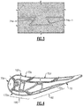
- FIG. 4 illustrates another example of an airfoil section 166.
- like reference numerals designate like elements where appropriate and reference numerals with the addition of one-hundred or multiples thereof designate modified elements that are understood to incorporate the same features and benefits of the corresponding elements.
- the exterior wall portion 72a includes a geometric segmented coating section 190.
- one or more of the panels 70 additionally or alternatively include a geometric segmented coating section 190.
- the panel 70a is shown with the coating section 190, although panels 70b, 70c, and/or 70d may also include a coating section 190.
- the coating section 190 includes a wall 192.
- the wall 192 includes a first or inner side 192a and a second or exterior side 192b that is opposite the first side 192a.
- the second side 192b includes an array of cells 194 defined by cell sidewalls 194a.
- the array is a repeating geometric pattern of one or more cell geometries.
- the cell sidewalls 194a have a uniform thickness.
- the cells 194 are hexagonal.
- the cells 194 may be circular, ovular, other polygonal geometry, or mixed cell geometries.
- the cells 194 may be machined or cast directly into the wall 192 (as a substrate), or machined into a metallic bond coating applied to the wall exterior side 192b. In the case where the cells 194 are machined or cast directly into the wall 192 (as a substrate), a metallic bond coating is applied.
- a ceramic based thermal barrier coating 196 ( Figure 5 ) is disposed in the array of cells 194.
- the cells 194 mechanically segment the coating. This segmentation induces stress relief cracks in the ceramic coating making it tolerant to sintering.
- the cells 194 thus provide good spallation resistance of the coating 196, particularly at higher temperature locations. In turn, greater spallation resistance may reduce the need for bleed air for cooling or enable use of higher temperature bleed air that is less of an efficiency penalty.
- the coating 196 may be a barrier coating, such as a thermal barrier or environmental barrier, which is formed of a ceramic material.
- the coating 196 may be a monolayer coating but more typically will be a multi-layer coating. For instance, the coating 196 has a first coating layer 196a and a second coating layer 196b. In this example, the second coating layer 196b is a topcoat.
- the ceramic material of the coating 196 provides thermal and/or environmental resistance.
- the ceramic material may include or may be yttria stabilized with zirconia, hafnia, and/or gadolinia, gadolinia zirconate, molybdate, alumina, or combinations thereof.
- the bond coat for attaching the ceramic material to the wall 192 may be formed of an alloy.
- Example alloys may include, but are not limited to, nickel alloys, cobalt alloys, a nickel alloy coated with cobalt or cobalt alloy, or a non-nickel alloys that do not substantially react with ceramic.
- the bond coat may include a nickel alloy, platinum, gold, silver, or MCrAlY, where the M includes at least one of nickel, cobalt, iron, or combinations thereof.
- the cell sidewalls 194a facilitate reducing internal stresses in the coating 196 that may occur from sintering at relatively high surface temperatures during use in the engine 20.
- the sintering may result in partial melting, densification, and diffusional shrinkage of the coating 196 and thereby induce internal stresses.
- the cell sidewalls 194a serve to produce faults in the coating 196.
- the faults provide locations for releasing energy associated with the internal stresses (e.g., reducing shear and radial stresses). That is, the energy associated with the internal stresses may be dissipated in the faults such that there is less energy available for causing delamination cracking between the coating 196 and the underlying wall 192.
- the coating section 190 may be formed using several different fabrication techniques.
- the wall 192 may be fabricated by investment casting, additive manufacturing, brazing, or combinations thereof, but is not limited to such techniques.
- the cells 194 can be separately fabricated and brazed to the remaining portion of the wall 192, which can be investment cast or additively fabricated.
- the cells 194 can be formed by other techniques, such as depositing an alloy bond coating and removing sections of the alloy coating by machining, electro-discharge machining (EDM), or other removal process.
- EDM electro-discharge machining
- the cells 194 can be machined into the wall 192 (as a substrate).
- the coating 196 ceramic coating material is deposited into the cells 194.
- the deposition process can include, but is not limited to, plasma spray or physical vapor deposition.
- plasma spray is used to produce a more durable version of the coating 196.
- the coating 196 has a laminar microstructure.
- the laminar microstructure includes grains of ceramic material that have a high aspect ratio.
- the laminar microstructure is a product of the plasma spray process, in which droplets of melted or partially melted ceramic material are sprayed onto the cells 194. Upon impact, the droplets flatten and solidify, yielding the laminar microstructure.
- the coating 196 has a porosity of less than 15%.
- the ceramic coating material fills or substantially fills the cells 194 and is deposited in a thickness that may be equal to or greater than the height of the cell sidewalls 194a.
- the surface of the coating may have contours from the underlying cells 194. If such contours are undesired, the surface may be machined, ground, or abraded flat. For instance, the surface is reduced down to or close to the tops of the cell sidewalls 194a.
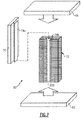
- Figure 7 illustrates an exploded view of selected components of the airfoil 60, with the components schematically represented.
- the panel 70 is secured to the core structure 72 by engaging the first connector 74a on the panel 70 with the second connector 74b on the core structure 72.
- the first connector 74a is slid into engagement with the second connector 74b.
- the dovetail 74a-1 is slidingly inserted into the doveslot 74b-1 ( Figure 3 ).
- a stop 200 may be provided on the core structure 72, the panel 70, or both. The stop 200 serves to prevent further insertion and to properly seat the panel 70. Additional panels 70 may be secured to the core structure 72 in a similar manner.
- the panels 70 and core structure 72 are then trapped between the platforms 62/64 to form the airfoil 60.
- the airfoil 60 can be disassembled, the core structure 72 and/or one or more panels 70 can be replaced with new ones, and the airfoil 60 can be reassembled.
- the core panels 70 and core structure 72 can be produced individually as new parts for an original airfoil or as replacement parts in an existing airfoil.
Landscapes
- Engineering & Computer Science (AREA)
- Mechanical Engineering (AREA)
- General Engineering & Computer Science (AREA)
- Chemical & Material Sciences (AREA)
- Materials Engineering (AREA)
- Combustion & Propulsion (AREA)
- Architecture (AREA)
- Composite Materials (AREA)
- Ceramic Engineering (AREA)
- Turbine Rotor Nozzle Sealing (AREA)
- Structures Of Non-Positive Displacement Pumps (AREA)
Claims (15)
- Profil aérodynamique (60) pour un moteur à turbine à gaz,
comprenant une section de profil aérodynamique (66) définissant un profil aérodynamique (AP),
la section de profil aérodynamique (66) incluant :un panneau (70) qui forme une partie du profil aérodynamique (AP), etune structure centrale (72) à laquelle le panneau (70) est fixé de manière amovible, caractérisé en ce que :
le panneau (70) inclut une section de revêtement segmentée géométriquement (190), la section de revêtement segmentée géométriquement (190) incluant une paroi (192) qui a un côté extérieur (192b), le côté extérieur (192b) incluant un réseau de cellules (194), et un revêtement (196) disposé dans le réseau de cellules (194). - Profil aérodynamique (60) selon la revendication 1, dans lequel le panneau (70) inclut un premier raccord (74a) et la structure centrale (72) inclut un second raccord (74b) qui est verrouillé avec le premier raccord (74a) dans un joint d'étanchéité qui fixe le panneau (70) à la structure centrale (72) .
- Profil aérodynamique (60) selon la revendication 2, dans lequel l'un parmi le premier raccord (74a) et le second raccord (74b) inclut une queue d'aronde (74a-1) et l'autre parmi le premier raccord (74a) et le second raccord (74b) inclut une encoche en queue d'aronde (74b-1).
- Profil aérodynamique (60) selon la revendication 1, 2 ou 3, dans lequel le panneau (70) inclut un passage intérieur (68).
- Profil aérodynamique (60) selon la revendication 4, dans lequel le panneau (70) inclut une paroi extérieure (76a) qui borde le passage intérieur (68), et un trou de refroidissement (78) qui s'étend à travers la paroi extérieure (76a) et qui s'ouvre sur le passage intérieur (68).
- Profil aérodynamique (60) selon une quelconque revendication précédente, dans lequel le panneau (70) est en céramique et la structure centrale (72) est en métal.
- Profil aérodynamique (60) selon une quelconque revendication précédente, dans lequel la structure centrale (72) inclut une paroi extérieure (72a) qui forme une partie du profil aérodynamique (AP), dans lequel, éventuellement, la paroi extérieure (72a) forme une extrémité arrière (TE) du profil aérodynamique (AP).
- Profil aérodynamique (60) selon une quelconque revendication précédente, comprenant en outre un panneau supplémentaire (70a, 70b, 70c, 70d) qui forme une partie différente du profil aérodynamique (AP) et qui est également fixé à la structure centrale (72), dans lequel, éventuellement, le panneau (70) et le panneau supplémentaire (70a, 70b, 70c, 70d) ont des compositions différentes.
- Profil aérodynamique (60) selon la revendication 8, dans lequel le panneau (70) est situé de manière adjacente au panneau supplémentaire (70a-70d), le panneau (70) et le panneau supplémentaire (70a-70d) définissant un trou de refroidissement (82) au niveau d'une interface de bord (80) entre eux.
- Profil aérodynamique (60) selon la revendication 8 ou 9, dans lequel le panneau (70) et le panneau supplémentaire (70a-70d) forment ensemble au moins une partie d'une extrémité avant (LE) du profil aérodynamique (AP).
- Profil aérodynamique (60) selon une quelconque revendication précédente, dans lequel la structure centrale (72) inclut un passage intérieur (68).
- Profil aérodynamique (60) selon une quelconque revendication précédente, dans lequel la structure centrale (72) inclut une section de revêtement segmentée géométriquement (190), la section de revêtement segmentée géométriquement (190) incluant une paroi (192) qui a un côté extérieur (192b), le côté extérieur (192b) incluant un réseau de cellules (194), et un revêtement (196) disposé dans le réseau de cellules (194).
- Moteur à turbine à gaz (20) comprenant :une section de compresseur (24) ;une chambre de combustion (56) en communication fluidique avec la section de compresseur (24) ; etune section de turbine (28) en communication fluidique avec la chambre de combustion (56), au moins l'une parmi la section de turbine (28) ou la section de compresseur (24) incluant un profil aérodynamique (60) selon une quelconque revendication précédente.
- Procédé de fabrication du profil aérodynamique (60) selon la revendication 1, le procédé comprenant la fixation du panneau (70) à la structure centrale pour former la section de profil aérodynamique (66).
- Procédé selon la revendication 14, dans lequel le panneau (70) inclut un premier raccord (74a) et la structure centrale (72) inclut un second raccord (74b), et la fixation inclut l'accouplement du premier raccord (74a) et du second raccord (74b) ensemble, dans lequel, éventuellement, l'un parmi le premier raccord (74a) et le second raccord (74b) inclut une queue d'aronde (74a-1) et l'autre parmi le premier raccord (74a) et le second raccord (74b) inclut une encoche en queue d'aronde (74b-1).
Applications Claiming Priority (1)
| Application Number | Priority Date | Filing Date | Title |
|---|---|---|---|
| US15/353,874 US10309226B2 (en) | 2016-11-17 | 2016-11-17 | Airfoil having panels |
Publications (2)
| Publication Number | Publication Date |
|---|---|
| EP3323982A1 EP3323982A1 (fr) | 2018-05-23 |
| EP3323982B1 true EP3323982B1 (fr) | 2021-05-19 |
Family
ID=60409159
Family Applications (1)
| Application Number | Title | Priority Date | Filing Date |
|---|---|---|---|
| EP17202239.4A Active EP3323982B1 (fr) | 2016-11-17 | 2017-11-17 | Profil aérodynamique, moteur à turbine à gaz ayant un tel profil et procédé de fabrication d'un profil aérodynamique |
Country Status (2)
| Country | Link |
|---|---|
| US (1) | US10309226B2 (fr) |
| EP (1) | EP3323982B1 (fr) |
Families Citing this family (4)
| Publication number | Priority date | Publication date | Assignee | Title |
|---|---|---|---|---|
| US10465715B2 (en) * | 2017-10-18 | 2019-11-05 | Goodrich Corporation | Blade with damping structures |
| US11365635B2 (en) * | 2019-05-17 | 2022-06-21 | Raytheon Technologies Corporation | CMC component with integral cooling channels and method of manufacture |
| US11536205B2 (en) * | 2020-03-31 | 2022-12-27 | Rolls-Royce Plc | Gas turbine engine operating schedules for optimizing ceramic matrix composite component life |
| US11286783B2 (en) * | 2020-04-27 | 2022-03-29 | Raytheon Technologies Corporation | Airfoil with CMC liner and multi-piece monolithic ceramic shell |
Family Cites Families (57)
| Publication number | Priority date | Publication date | Assignee | Title |
|---|---|---|---|---|
| US3215511A (en) | 1962-03-30 | 1965-11-02 | Union Carbide Corp | Gas turbine nozzle vane and like articles |
| GB1487063A (en) | 1974-08-23 | 1977-09-28 | Rolls Royce | Aero-foil member for a gas turbine engine |
| US4137008A (en) | 1977-09-21 | 1979-01-30 | The United States Of America As Represented By The Secretary Of The Navy | Adjustable blowing slot for circulation control airfoil |
| US4247259A (en) | 1979-04-18 | 1981-01-27 | Avco Corporation | Composite ceramic/metallic turbine blade and method of making same |
| DE3110098C2 (de) | 1981-03-16 | 1983-03-17 | MTU Motoren- und Turbinen-Union München GmbH, 8000 München | Turbinenleitschaufel für Gasturbinentriebwerke |
| US4786234A (en) | 1982-06-21 | 1988-11-22 | Teledyne Industries, Inc. | Turbine airfoil |
| JPS6166802A (ja) | 1984-09-10 | 1986-04-05 | Mitsubishi Heavy Ind Ltd | ガスタ−ビンのタ−ビン翼 |
| US4914794A (en) | 1986-08-07 | 1990-04-10 | Allied-Signal Inc. | Method of making an abradable strain-tolerant ceramic coated turbine shroud |
| US4867639A (en) * | 1987-09-22 | 1989-09-19 | Allied-Signal Inc. | Abradable shroud coating |
| US5030060A (en) * | 1988-10-20 | 1991-07-09 | The United States Of America As Represented By The Secretary Of The Air Force | Method and apparatus for cooling high temperature ceramic turbine blade portions |
| JPH05321602A (ja) | 1992-05-25 | 1993-12-07 | Toshiba Corp | ガスタービン動翼 |
| DE4238369C2 (de) | 1992-11-13 | 1996-09-26 | Mtu Muenchen Gmbh | Bauteil aus einem metallischen Grundsubstrat mit keramischer Beschichtung |
| US5419971A (en) | 1993-03-03 | 1995-05-30 | General Electric Company | Enhanced thermal barrier coating system |
| US5358379A (en) | 1993-10-27 | 1994-10-25 | Westinghouse Electric Corporation | Gas turbine vane |
| US5538380A (en) | 1994-06-27 | 1996-07-23 | Solar Turbines Incorporated | Metallic nut for use with ceramic threads |
| US5558922A (en) | 1994-12-28 | 1996-09-24 | General Electric Company | Thick thermal barrier coating having grooves for enhanced strain tolerance |
| US5634771A (en) | 1995-09-25 | 1997-06-03 | General Electric Company | Partially-metallic blade for a gas turbine |
| US6102656A (en) | 1995-09-26 | 2000-08-15 | United Technologies Corporation | Segmented abradable ceramic coating |
| DE19617556A1 (de) * | 1996-05-02 | 1997-11-06 | Asea Brown Boveri | Thermisch belastete Schaufel für eine Strömungsmaschine |
| US5951892A (en) | 1996-12-10 | 1999-09-14 | Chromalloy Gas Turbine Corporation | Method of making an abradable seal by laser cutting |
| US6224963B1 (en) | 1997-05-14 | 2001-05-01 | Alliedsignal Inc. | Laser segmented thick thermal barrier coatings for turbine shrouds |
| US6000906A (en) | 1997-09-12 | 1999-12-14 | Alliedsignal Inc. | Ceramic airfoil |
| US6224339B1 (en) | 1998-07-08 | 2001-05-01 | Allison Advanced Development Company | High temperature airfoil |
| US6316078B1 (en) | 2000-03-14 | 2001-11-13 | The United States Of America As Represented By The Administrator Of The National Aeronautics And Space Administration | Segmented thermal barrier coating |
| US6514046B1 (en) | 2000-09-29 | 2003-02-04 | Siemens Westinghouse Power Corporation | Ceramic composite vane with metallic substructure |
| US6846574B2 (en) | 2001-05-16 | 2005-01-25 | Siemens Westinghouse Power Corporation | Honeycomb structure thermal barrier coating |
| US6543996B2 (en) | 2001-06-28 | 2003-04-08 | General Electric Company | Hybrid turbine nozzle |
| US6703137B2 (en) | 2001-08-02 | 2004-03-09 | Siemens Westinghouse Power Corporation | Segmented thermal barrier coating and method of manufacturing the same |
| US6709230B2 (en) | 2002-05-31 | 2004-03-23 | Siemens Westinghouse Power Corporation | Ceramic matrix composite gas turbine vane |
| US7080971B2 (en) | 2003-03-12 | 2006-07-25 | Florida Turbine Technologies, Inc. | Cooled turbine spar shell blade construction |
| US7104756B2 (en) | 2004-08-11 | 2006-09-12 | United Technologies Corporation | Temperature tolerant vane assembly |
| US7435058B2 (en) | 2005-01-18 | 2008-10-14 | Siemens Power Generation, Inc. | Ceramic matrix composite vane with chordwise stiffener |
| US7326030B2 (en) | 2005-02-02 | 2008-02-05 | Siemens Power Generation, Inc. | Support system for a composite airfoil in a turbine engine |
| US7316539B2 (en) | 2005-04-07 | 2008-01-08 | Siemens Power Generation, Inc. | Vane assembly with metal trailing edge segment |
| US7452182B2 (en) | 2005-04-07 | 2008-11-18 | Siemens Energy, Inc. | Multi-piece turbine vane assembly |
| US7329087B2 (en) | 2005-09-19 | 2008-02-12 | General Electric Company | Seal-less CMC vane to platform interfaces |
| US7686570B2 (en) * | 2006-08-01 | 2010-03-30 | Siemens Energy, Inc. | Abradable coating system |
| US7520725B1 (en) | 2006-08-11 | 2009-04-21 | Florida Turbine Technologies, Inc. | Turbine airfoil with near-wall leading edge multi-holes cooling |
| US9039358B2 (en) | 2007-01-03 | 2015-05-26 | United Technologies Corporation | Replaceable blade outer air seal design |
| US20100136258A1 (en) | 2007-04-25 | 2010-06-03 | Strock Christopher W | Method for improved ceramic coating |
| US7963745B1 (en) | 2007-07-10 | 2011-06-21 | Florida Turbine Technologies, Inc. | Composite turbine blade |
| US8182208B2 (en) | 2007-07-10 | 2012-05-22 | United Technologies Corp. | Gas turbine systems involving feather seals |
| US8202043B2 (en) | 2007-10-15 | 2012-06-19 | United Technologies Corp. | Gas turbine engines and related systems involving variable vanes |
| US8079806B2 (en) | 2007-11-28 | 2011-12-20 | United Technologies Corporation | Segmented ceramic layer for member of gas turbine engine |
| GB2458685B (en) | 2008-03-28 | 2010-05-12 | Rolls Royce Plc | An article formed from a composite material |
| US8167573B2 (en) | 2008-09-19 | 2012-05-01 | Siemens Energy, Inc. | Gas turbine airfoil |
| US8251651B2 (en) | 2009-01-28 | 2012-08-28 | United Technologies Corporation | Segmented ceramic matrix composite turbine airfoil component |
| US8109724B2 (en) | 2009-03-26 | 2012-02-07 | United Technologies Corporation | Recessed metering standoffs for airfoil baffle |
| US8585368B2 (en) | 2009-04-16 | 2013-11-19 | United Technologies Corporation | Hybrid structure airfoil |
| US8366392B1 (en) | 2009-05-06 | 2013-02-05 | Florida Turbine Technologies, Inc. | Composite air cooled turbine rotor blade |
| US8197211B1 (en) | 2009-09-25 | 2012-06-12 | Florida Turbine Technologies, Inc. | Composite air cooled turbine rotor blade |
| US9528382B2 (en) | 2009-11-10 | 2016-12-27 | General Electric Company | Airfoil heat shield |
| US8506243B2 (en) | 2009-11-19 | 2013-08-13 | United Technologies Corporation | Segmented thermally insulating coating |
| EP2696028A1 (fr) | 2012-08-06 | 2014-02-12 | Siemens Aktiengesellschaft | Composant de turbomachine pour courant de gaz chauds d'une turbine à gaz |
| DE102013219774A1 (de) | 2013-09-30 | 2015-04-02 | MTU Aero Engines AG | Schaufel für eine Gasturbine |
| WO2015108592A2 (fr) | 2013-11-22 | 2015-07-23 | United Technologies Corporation | Profil aérodynamique de turbine à matériaux multiples |
| US10107117B2 (en) | 2014-09-30 | 2018-10-23 | United Technologies Corporation | Airfoil assembly with spacer and tie-spar |
-
2016
- 2016-11-17 US US15/353,874 patent/US10309226B2/en active Active
-
2017
- 2017-11-17 EP EP17202239.4A patent/EP3323982B1/fr active Active
Non-Patent Citations (1)
| Title |
|---|
| None * |
Also Published As
| Publication number | Publication date |
|---|---|
| US20180135417A1 (en) | 2018-05-17 |
| US10309226B2 (en) | 2019-06-04 |
| EP3323982A1 (fr) | 2018-05-23 |
Similar Documents
| Publication | Publication Date | Title |
|---|---|---|
| EP3323985B1 (fr) | Profil aérodynamique, article de moteur à turbine à gaz, moteur à turbine à gaz et procédé de fabrication d'un profil aérodynamique associés | |
| EP3336314B1 (fr) | Profil aérodynamique comportant une section de revêtement segmentée géométriquement et présentant une caractéristique de liaison secondaire mécanique | |
| EP3323984A1 (fr) | Profil aérodynamique comportant une section de revêtement segmentée géométriquement | |
| US11149573B2 (en) | Airfoil with seal between end wall and airfoil section | |
| EP3323982B1 (fr) | Profil aérodynamique, moteur à turbine à gaz ayant un tel profil et procédé de fabrication d'un profil aérodynamique | |
| EP3339571B1 (fr) | Profil aérodynamique comportant un panneau ayant un guide d'écoulement | |
| EP3323990A1 (fr) | Profil aérodynamique, moteur à turbine à gaz associé et procédé d'assemblage d'un profil aérodynamique | |
| US11319817B2 (en) | Airfoil with panel and side edge cooling | |
| EP3323999B1 (fr) | Segments d'arc de paroi terminale comportant un couvercle à la jointure | |
| EP3323983B1 (fr) | Aube fixe et moteur à turbine à gaz ayant une telle aube | |
| EP3323986B1 (fr) | Profil aérodynamique comportant une section de revêtement segmentée géométriquement | |
| EP3336309B1 (fr) | Profil aérodynamique avec panneau fixé à une structure centrale | |
| EP3323996B1 (fr) | Composant de moteur à turbine avec section de revêtement segmenté géométriquement et passage de refroidissement | |
| EP3556998B1 (fr) | Joint d'air ayant une partie de trajectoire de gaz comportant un revêtement segmenté géométriquement |
Legal Events
| Date | Code | Title | Description |
|---|---|---|---|
| PUAI | Public reference made under article 153(3) epc to a published international application that has entered the european phase |
Free format text: ORIGINAL CODE: 0009012 |
|
| STAA | Information on the status of an ep patent application or granted ep patent |
Free format text: STATUS: THE APPLICATION HAS BEEN PUBLISHED |
|
| AK | Designated contracting states |
Kind code of ref document: A1 Designated state(s): AL AT BE BG CH CY CZ DE DK EE ES FI FR GB GR HR HU IE IS IT LI LT LU LV MC MK MT NL NO PL PT RO RS SE SI SK SM TR |
|
| AX | Request for extension of the european patent |
Extension state: BA ME |
|
| STAA | Information on the status of an ep patent application or granted ep patent |
Free format text: STATUS: REQUEST FOR EXAMINATION WAS MADE |
|
| 17P | Request for examination filed |
Effective date: 20181123 |
|
| RBV | Designated contracting states (corrected) |
Designated state(s): AL AT BE BG CH CY CZ DE DK EE ES FI FR GB GR HR HU IE IS IT LI LT LU LV MC MK MT NL NO PL PT RO RS SE SI SK SM TR |
|
| GRAP | Despatch of communication of intention to grant a patent |
Free format text: ORIGINAL CODE: EPIDOSNIGR1 |
|
| STAA | Information on the status of an ep patent application or granted ep patent |
Free format text: STATUS: GRANT OF PATENT IS INTENDED |
|
| INTG | Intention to grant announced |
Effective date: 20201222 |
|
| RAP1 | Party data changed (applicant data changed or rights of an application transferred) |
Owner name: RAYTHEON TECHNOLOGIES CORPORATION |
|
| GRAS | Grant fee paid |
Free format text: ORIGINAL CODE: EPIDOSNIGR3 |
|
| GRAA | (expected) grant |
Free format text: ORIGINAL CODE: 0009210 |
|
| STAA | Information on the status of an ep patent application or granted ep patent |
Free format text: STATUS: THE PATENT HAS BEEN GRANTED |
|
| AK | Designated contracting states |
Kind code of ref document: B1 Designated state(s): AL AT BE BG CH CY CZ DE DK EE ES FI FR GB GR HR HU IE IS IT LI LT LU LV MC MK MT NL NO PL PT RO RS SE SI SK SM TR |
|
| REG | Reference to a national code |
Ref country code: GB Ref legal event code: FG4D |
|
| REG | Reference to a national code |
Ref country code: CH Ref legal event code: EP |
|
| REG | Reference to a national code |
Ref country code: DE Ref legal event code: R096 Ref document number: 602017038760 Country of ref document: DE |
|
| REG | Reference to a national code |
Ref country code: AT Ref legal event code: REF Ref document number: 1394128 Country of ref document: AT Kind code of ref document: T Effective date: 20210615 |
|
| REG | Reference to a national code |
Ref country code: IE Ref legal event code: FG4D |
|
| REG | Reference to a national code |
Ref country code: LT Ref legal event code: MG9D |
|
| REG | Reference to a national code |
Ref country code: AT Ref legal event code: MK05 Ref document number: 1394128 Country of ref document: AT Kind code of ref document: T Effective date: 20210519 |
|
| REG | Reference to a national code |
Ref country code: NL Ref legal event code: MP Effective date: 20210519 |
|
| PG25 | Lapsed in a contracting state [announced via postgrant information from national office to epo] |
Ref country code: LT Free format text: LAPSE BECAUSE OF FAILURE TO SUBMIT A TRANSLATION OF THE DESCRIPTION OR TO PAY THE FEE WITHIN THE PRESCRIBED TIME-LIMIT Effective date: 20210519 Ref country code: FI Free format text: LAPSE BECAUSE OF FAILURE TO SUBMIT A TRANSLATION OF THE DESCRIPTION OR TO PAY THE FEE WITHIN THE PRESCRIBED TIME-LIMIT Effective date: 20210519 Ref country code: BG Free format text: LAPSE BECAUSE OF FAILURE TO SUBMIT A TRANSLATION OF THE DESCRIPTION OR TO PAY THE FEE WITHIN THE PRESCRIBED TIME-LIMIT Effective date: 20210819 Ref country code: AT Free format text: LAPSE BECAUSE OF FAILURE TO SUBMIT A TRANSLATION OF THE DESCRIPTION OR TO PAY THE FEE WITHIN THE PRESCRIBED TIME-LIMIT Effective date: 20210519 Ref country code: HR Free format text: LAPSE BECAUSE OF FAILURE TO SUBMIT A TRANSLATION OF THE DESCRIPTION OR TO PAY THE FEE WITHIN THE PRESCRIBED TIME-LIMIT Effective date: 20210519 |
|
| PG25 | Lapsed in a contracting state [announced via postgrant information from national office to epo] |
Ref country code: RS Free format text: LAPSE BECAUSE OF FAILURE TO SUBMIT A TRANSLATION OF THE DESCRIPTION OR TO PAY THE FEE WITHIN THE PRESCRIBED TIME-LIMIT Effective date: 20210519 Ref country code: SE Free format text: LAPSE BECAUSE OF FAILURE TO SUBMIT A TRANSLATION OF THE DESCRIPTION OR TO PAY THE FEE WITHIN THE PRESCRIBED TIME-LIMIT Effective date: 20210519 Ref country code: PL Free format text: LAPSE BECAUSE OF FAILURE TO SUBMIT A TRANSLATION OF THE DESCRIPTION OR TO PAY THE FEE WITHIN THE PRESCRIBED TIME-LIMIT Effective date: 20210519 Ref country code: PT Free format text: LAPSE BECAUSE OF FAILURE TO SUBMIT A TRANSLATION OF THE DESCRIPTION OR TO PAY THE FEE WITHIN THE PRESCRIBED TIME-LIMIT Effective date: 20210920 Ref country code: NO Free format text: LAPSE BECAUSE OF FAILURE TO SUBMIT A TRANSLATION OF THE DESCRIPTION OR TO PAY THE FEE WITHIN THE PRESCRIBED TIME-LIMIT Effective date: 20210819 Ref country code: GR Free format text: LAPSE BECAUSE OF FAILURE TO SUBMIT A TRANSLATION OF THE DESCRIPTION OR TO PAY THE FEE WITHIN THE PRESCRIBED TIME-LIMIT Effective date: 20210820 Ref country code: LV Free format text: LAPSE BECAUSE OF FAILURE TO SUBMIT A TRANSLATION OF THE DESCRIPTION OR TO PAY THE FEE WITHIN THE PRESCRIBED TIME-LIMIT Effective date: 20210519 Ref country code: IS Free format text: LAPSE BECAUSE OF FAILURE TO SUBMIT A TRANSLATION OF THE DESCRIPTION OR TO PAY THE FEE WITHIN THE PRESCRIBED TIME-LIMIT Effective date: 20210919 |
|
| PG25 | Lapsed in a contracting state [announced via postgrant information from national office to epo] |
Ref country code: NL Free format text: LAPSE BECAUSE OF FAILURE TO SUBMIT A TRANSLATION OF THE DESCRIPTION OR TO PAY THE FEE WITHIN THE PRESCRIBED TIME-LIMIT Effective date: 20210519 |
|
| PG25 | Lapsed in a contracting state [announced via postgrant information from national office to epo] |
Ref country code: SM Free format text: LAPSE BECAUSE OF FAILURE TO SUBMIT A TRANSLATION OF THE DESCRIPTION OR TO PAY THE FEE WITHIN THE PRESCRIBED TIME-LIMIT Effective date: 20210519 Ref country code: SK Free format text: LAPSE BECAUSE OF FAILURE TO SUBMIT A TRANSLATION OF THE DESCRIPTION OR TO PAY THE FEE WITHIN THE PRESCRIBED TIME-LIMIT Effective date: 20210519 Ref country code: CZ Free format text: LAPSE BECAUSE OF FAILURE TO SUBMIT A TRANSLATION OF THE DESCRIPTION OR TO PAY THE FEE WITHIN THE PRESCRIBED TIME-LIMIT Effective date: 20210519 Ref country code: DK Free format text: LAPSE BECAUSE OF FAILURE TO SUBMIT A TRANSLATION OF THE DESCRIPTION OR TO PAY THE FEE WITHIN THE PRESCRIBED TIME-LIMIT Effective date: 20210519 Ref country code: EE Free format text: LAPSE BECAUSE OF FAILURE TO SUBMIT A TRANSLATION OF THE DESCRIPTION OR TO PAY THE FEE WITHIN THE PRESCRIBED TIME-LIMIT Effective date: 20210519 Ref country code: RO Free format text: LAPSE BECAUSE OF FAILURE TO SUBMIT A TRANSLATION OF THE DESCRIPTION OR TO PAY THE FEE WITHIN THE PRESCRIBED TIME-LIMIT Effective date: 20210519 Ref country code: ES Free format text: LAPSE BECAUSE OF FAILURE TO SUBMIT A TRANSLATION OF THE DESCRIPTION OR TO PAY THE FEE WITHIN THE PRESCRIBED TIME-LIMIT Effective date: 20210519 |
|
| REG | Reference to a national code |
Ref country code: DE Ref legal event code: R097 Ref document number: 602017038760 Country of ref document: DE |
|
| PLBE | No opposition filed within time limit |
Free format text: ORIGINAL CODE: 0009261 |
|
| STAA | Information on the status of an ep patent application or granted ep patent |
Free format text: STATUS: NO OPPOSITION FILED WITHIN TIME LIMIT |
|
| 26N | No opposition filed |
Effective date: 20220222 |
|
| PG25 | Lapsed in a contracting state [announced via postgrant information from national office to epo] |
Ref country code: IS Free format text: LAPSE BECAUSE OF FAILURE TO SUBMIT A TRANSLATION OF THE DESCRIPTION OR TO PAY THE FEE WITHIN THE PRESCRIBED TIME-LIMIT Effective date: 20210919 Ref country code: AL Free format text: LAPSE BECAUSE OF FAILURE TO SUBMIT A TRANSLATION OF THE DESCRIPTION OR TO PAY THE FEE WITHIN THE PRESCRIBED TIME-LIMIT Effective date: 20210519 |
|
| PG25 | Lapsed in a contracting state [announced via postgrant information from national office to epo] |
Ref country code: MC Free format text: LAPSE BECAUSE OF FAILURE TO SUBMIT A TRANSLATION OF THE DESCRIPTION OR TO PAY THE FEE WITHIN THE PRESCRIBED TIME-LIMIT Effective date: 20210519 |
|
| REG | Reference to a national code |
Ref country code: CH Ref legal event code: PL |
|
| PG25 | Lapsed in a contracting state [announced via postgrant information from national office to epo] |
Ref country code: LU Free format text: LAPSE BECAUSE OF NON-PAYMENT OF DUE FEES Effective date: 20211117 Ref country code: IT Free format text: LAPSE BECAUSE OF FAILURE TO SUBMIT A TRANSLATION OF THE DESCRIPTION OR TO PAY THE FEE WITHIN THE PRESCRIBED TIME-LIMIT Effective date: 20210519 Ref country code: BE Free format text: LAPSE BECAUSE OF NON-PAYMENT OF DUE FEES Effective date: 20211130 |
|
| REG | Reference to a national code |
Ref country code: BE Ref legal event code: MM Effective date: 20211130 |
|
| PG25 | Lapsed in a contracting state [announced via postgrant information from national office to epo] |
Ref country code: IE Free format text: LAPSE BECAUSE OF NON-PAYMENT OF DUE FEES Effective date: 20211117 |
|
| PG25 | Lapsed in a contracting state [announced via postgrant information from national office to epo] |
Ref country code: HU Free format text: LAPSE BECAUSE OF FAILURE TO SUBMIT A TRANSLATION OF THE DESCRIPTION OR TO PAY THE FEE WITHIN THE PRESCRIBED TIME-LIMIT; INVALID AB INITIO Effective date: 20171117 |
|
| P01 | Opt-out of the competence of the unified patent court (upc) registered |
Effective date: 20230520 |
|
| PG25 | Lapsed in a contracting state [announced via postgrant information from national office to epo] |
Ref country code: CY Free format text: LAPSE BECAUSE OF FAILURE TO SUBMIT A TRANSLATION OF THE DESCRIPTION OR TO PAY THE FEE WITHIN THE PRESCRIBED TIME-LIMIT Effective date: 20210519 |
|
| PG25 | Lapsed in a contracting state [announced via postgrant information from national office to epo] |
Ref country code: LI Free format text: LAPSE BECAUSE OF NON-PAYMENT OF DUE FEES Effective date: 20220701 Ref country code: CH Free format text: LAPSE BECAUSE OF NON-PAYMENT OF DUE FEES Effective date: 20220701 |
|
| PG25 | Lapsed in a contracting state [announced via postgrant information from national office to epo] |
Ref country code: MK Free format text: LAPSE BECAUSE OF FAILURE TO SUBMIT A TRANSLATION OF THE DESCRIPTION OR TO PAY THE FEE WITHIN THE PRESCRIBED TIME-LIMIT Effective date: 20210519 |
|
| PG25 | Lapsed in a contracting state [announced via postgrant information from national office to epo] |
Ref country code: MT Free format text: LAPSE BECAUSE OF FAILURE TO SUBMIT A TRANSLATION OF THE DESCRIPTION OR TO PAY THE FEE WITHIN THE PRESCRIBED TIME-LIMIT Effective date: 20210519 |
|
| REG | Reference to a national code |
Ref country code: DE Ref legal event code: R081 Ref document number: 602017038760 Country of ref document: DE Owner name: RTX CORPORATION (N.D.GES.D. STAATES DELAWARE),, US Free format text: FORMER OWNER: RAYTHEON TECHNOLOGIES CORPORATION, FARMINGTON, CT, US |
|
| PG25 | Lapsed in a contracting state [announced via postgrant information from national office to epo] |
Ref country code: TR Free format text: LAPSE BECAUSE OF FAILURE TO SUBMIT A TRANSLATION OF THE DESCRIPTION OR TO PAY THE FEE WITHIN THE PRESCRIBED TIME-LIMIT Effective date: 20210519 |
|
| PGFP | Annual fee paid to national office [announced via postgrant information from national office to epo] |
Ref country code: DE Payment date: 20251022 Year of fee payment: 9 |
|
| PGFP | Annual fee paid to national office [announced via postgrant information from national office to epo] |
Ref country code: GB Payment date: 20251023 Year of fee payment: 9 |
|
| PGFP | Annual fee paid to national office [announced via postgrant information from national office to epo] |
Ref country code: FR Payment date: 20251022 Year of fee payment: 9 |