EP3059146B1 - Fahrzeug mit heckspoiler - Google Patents
Fahrzeug mit heckspoiler Download PDFInfo
- Publication number
- EP3059146B1 EP3059146B1 EP16156157.6A EP16156157A EP3059146B1 EP 3059146 B1 EP3059146 B1 EP 3059146B1 EP 16156157 A EP16156157 A EP 16156157A EP 3059146 B1 EP3059146 B1 EP 3059146B1
- Authority
- EP
- European Patent Office
- Prior art keywords
- rear spoiler
- car
- aerodynamic duct
- aerodynamic
- spoiler
- Prior art date
- Legal status (The legal status is an assumption and is not a legal conclusion. Google has not performed a legal analysis and makes no representation as to the accuracy of the status listed.)
- Active
Links
Images


Classifications
-
- B—PERFORMING OPERATIONS; TRANSPORTING
- B62—LAND VEHICLES FOR TRAVELLING OTHERWISE THAN ON RAILS
- B62D—MOTOR VEHICLES; TRAILERS
- B62D35/00—Vehicle bodies characterised by streamlining
- B62D35/007—Rear spoilers
-
- B—PERFORMING OPERATIONS; TRANSPORTING
- B60—VEHICLES IN GENERAL
- B60K—ARRANGEMENT OR MOUNTING OF PROPULSION UNITS OR OF TRANSMISSIONS IN VEHICLES; ARRANGEMENT OR MOUNTING OF PLURAL DIVERSE PRIME-MOVERS IN VEHICLES; AUXILIARY DRIVES FOR VEHICLES; INSTRUMENTATION OR DASHBOARDS FOR VEHICLES; ARRANGEMENTS IN CONNECTION WITH COOLING, AIR INTAKE, GAS EXHAUST OR FUEL SUPPLY OF PROPULSION UNITS IN VEHICLES
- B60K8/00—Arrangement or mounting of propulsion units not provided for in one of main groups B60K1/00 - B60K7/00
-
- B—PERFORMING OPERATIONS; TRANSPORTING
- B62—LAND VEHICLES FOR TRAVELLING OTHERWISE THAN ON RAILS
- B62D—MOTOR VEHICLES; TRAILERS
- B62D35/00—Vehicle bodies characterised by streamlining
-
- B—PERFORMING OPERATIONS; TRANSPORTING
- B62—LAND VEHICLES FOR TRAVELLING OTHERWISE THAN ON RAILS
- B62D—MOTOR VEHICLES; TRAILERS
- B62D37/00—Stabilising vehicle bodies without controlling suspension arrangements
- B62D37/02—Stabilising vehicle bodies without controlling suspension arrangements by aerodynamic means
-
- Y—GENERAL TAGGING OF NEW TECHNOLOGICAL DEVELOPMENTS; GENERAL TAGGING OF CROSS-SECTIONAL TECHNOLOGIES SPANNING OVER SEVERAL SECTIONS OF THE IPC; TECHNICAL SUBJECTS COVERED BY FORMER USPC CROSS-REFERENCE ART COLLECTIONS [XRACs] AND DIGESTS
- Y02—TECHNOLOGIES OR APPLICATIONS FOR MITIGATION OR ADAPTATION AGAINST CLIMATE CHANGE
- Y02T—CLIMATE CHANGE MITIGATION TECHNOLOGIES RELATED TO TRANSPORTATION
- Y02T10/00—Road transport of goods or passengers
- Y02T10/80—Technologies aiming to reduce greenhouse gasses emissions common to all road transportation technologies
- Y02T10/82—Elements for improving aerodynamics
Definitions
- the present invention relates to a car provided with a rear spoiler.
- the aerodynamics are designed to generate a strong negative lift (i.e., a strong downforce) while at the same time reducing drag to a minimum.
- a strong negative lift i.e., a strong downforce
- the aerodynamic efficiency of a car is measured as a function of the ratio between the negative lift and the corresponding drag: the higher this ratio, the greater the aerodynamic efficiency of the car.
- a method known in the prior art consists of mounting a rear spoiler, i.e., an aerodynamic element projecting from the outline of the car body that deflects the air flow upwards.
- the rear spoiler is an element that extends upwards from the car body and constitutes a seamless extension of said car body; thus, the air flow is forced to bypass the rear spoiler, i.e. to pass over the rear spoiler without any possibility of passing beneath said rear spoiler.
- a rear wing which comprises at least one winged profile arranged at a certain distance from the rest of the car body and is usually supported by a central support or by two lateral supports; the air flow hits the winged profile on both its upper surface and its lower surface, generating a downforce according to the same principle of physics that explains how aeroplanes fly.
- a rear wing is a relatively bulky element and may be associated with several drawbacks (such as higher production costs, reduced rear visibility, restricted access to the rear compartment, which may house the engine or a boot) .
- Patent application WO2014020342A1 and patent US5346274A describe a car comprising a rear spoiler that is integral with the car body, is arranged in a rear position and projects from the outline of the car body to deflect the air flow upwards so that the air flow skims over an upper surface of said rear spoiler;
- the rear spoiler comprises a through aerodynamic duct which starts in an inlet opening arranged in correspondence with an initial end of the rear spoiler and ends in an outlet opening arranged in correspondence with a final end of the rear spoiler so that a part of the air flow hitting the rear spoiler flows above the rear spoiler skimming over the upper surface of said rear spoiler and the remaining part of the air flow hitting the rear spoiler flows through the rear spoiler crossing the aerodynamic duct.
- the aerodynamic duct has a constant cross-section which remains the same along the entire length of said aerodynamic duct, while in patent US5346274A the aerodynamic duct has a continuously variable cross-section which continuously varies along the entire length of said aerodynamic duct.
- the purpose of the present invention is to provide a car provided with a rear spoiler, said car having good aerodynamic efficiency in the rear part and, at the same time, being easy and economical to produce.
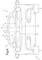
- reference numeral 1 globally denotes a car powered by means of an internal combustion engine arranged in a central position.
- the car 1 comprises a chassis, which supports the internal combustion engine, a pair of front wheels 2, and a pair of rear wheels 3.
- a passenger compartment 4 which is accessed through a pair of doors 5.
- an engine compartment 6 (partially illustrated in figures 2 , 3 and 4 ) which houses the internal combustion engine.
- the chassis is covered by a car body 7 which comprises, among other things, the doors 5, a transparent windscreen 8 which delimits the passenger compartment 4 at the front and a roof 9 that delimits the passenger compartment 4 on the upper side.
- a rear spoiler 10 (illustrated in figures 2 , 3 and 4 ) which is a continuation of the car body 7.
- the car body 7 comprises a rear panel system 11 (illustrated in figures 2 , 3 and 4 ), which joins the roof 9 to the rear area, closes the engine compartment 6 at the top and ends in correspondence with the rear spoiler 10.
- the rear spoiler 10 is integral with the car body 7, constitutes a seamless continuation of the car body 7, is arranged in a rear position and projects from the outline of the car body 7 to deflect the air flow upwards so that the air flow skims over an upper surface 12 of said rear spoiler 10.
- the rear spoiler 10 comprises a through aerodynamic duct 13 which starts in an inlet opening 14 arranged in correspondence with an initial (front) end of the rear spoiler 10 and ends in an outlet opening 15 arranged in correspondence with a final (rear) end of the rear spoiler 10 so that (as is clearly illustrated in figure 5 ) a part of the air flow hitting the rear spoiler 10 flows above the rear spoiler 10 skimming over the upper surface 12 of said rear spoiler 10 and the remaining part of the air flow hitting the rear spoiler 10 flows through the rear spoiler 10 crossing the aerodynamic duct 13.
- the rear spoiler 10 comprises a single aerodynamic duct 13; according to a different and perfectly equivalent embodiment, the rear spoiler 10 comprises two or three aerodynamic ducts 13 arranged side by side and separated from one another by a corresponding dividing wall.
- the aerodynamic duct 13 has, on the inside, a narrowing 16, which locally reduces the area of the cross section (i.e., only along a short section of the length when compared to the entire length of the aerodynamic duct 13).
- the area of the cross section of the aerodynamic duct 13 is substantially constant along the entire length of the aerodynamic duct 13 with the sole exception of the narrowing 16; as a consequence, the area of the cross section of the aerodynamic duct 13 upstream of the narrowing 16 is substantially equal to the area of the cross section of the aerodynamic duct 13 downstream of the narrowing 16.
- the narrowing 16 of the aerodynamic duct 13 consists of a deflector profile 17 that projects towards the inside of the aerodynamic duct 13.
- the deflector profile 17 is movable so as to change its position on the inside of the aerodynamic duct 13; in particular, it is provided with an actuator 18 (for example an electric motor) that is mechanically connected to the deflector profile 17 so as to move the position of the deflector profile 17 on the inside of the aerodynamic duct 13 between a position of maximum incidence (and thus maximum narrowing) and a position of minimum incidence (thus of minimum narrowing).
- an actuator 18 for example an electric motor
- Changing the position of the deflector profile 17 changes the impact of the narrowing 16 in the aerodynamic duct 13 and thus changes the air flow rate through the aerodynamic duct 13 (the greater the narrowing, the lower the air flow rate through the aerodynamic duct 13) in relation to the air flow rate over the rear spoiler 10; as a consequence, by changing the position of the deflector profile 17 it is possible to increase/decrease the negative lift (i.e., the downforce) generated by the rear spoiler 10 and at the same time decrease/increase the drag generated by the rear spoiler 10. Thus, by changing the position of the deflector profile 17 it is possible to adjust (optimise) the aerodynamic action of the rear spoiler 10 in relation to the state of motion of the car 1.
- the rear spoiler 10 has a cross section of a triangular shape and has the upper surface 12 over which the air flow flowing above the rear spoiler 10 skims, a lower surface 19 which delimits the aerodynamic duct 13 on the upper side, and a rear surface 20.
- the rear panel system 11 ends in correspondence with the rear spoiler 10 and is joined without discontinuity (i.e., without any gaps and with no abrupt slope gradient variations) to a lower surface 21 of the aerodynamic duct 13.
- the rear panel system 11 has the same inclination as the lower surface 21 of the aerodynamic duct 13 at least close to the rear spoiler 10.
- the car body 7 comprises two side boards 22, which are arranged on opposite sides of the rear panel system 11 and are arranged so as to converge in order to progressively reduce the distance between them as they get closer to the rear spoiler 10.
- the two side boards 22 end in correspondence with lateral edges of the inlet opening 14 of the aerodynamic duct 13.
- the rear panel system 11 comprises a fixed panel 23 arranged in correspondence with the rear spoiler 10 and a movable panel 24 which is arranged between the roof 9 and the panel 23 and constitutes a hood of the engine compartment 6.
- the rear spoiler 10 described above achieves good aerodynamic efficiency, i.e., it has a very favourable ratio between the negative lift and the corresponding drag. This result is achieved owing to the presence of the aerodynamic duct 13 thanks to which it is possible to increase the aerodynamic recompression in correspondence with the rear panel system 11 increasing the negative lift (i.e. downforce) without any significant increase in drag.
- the aerodynamic action of the rear spoiler 10 described above can be adjusted easily, quickly and accurately by increasing or decreasing the negative lift that is generated, in real-time.
- the rear spoiler 10 described above is easy and economical to produce, in that it may be entirely made by appropriately shaping existing components of the car body 7 (i.e. without the need for any additional components other than the deflector profile 17 and the respective actuator 18 of the deflector profile 17).
Landscapes
- Engineering & Computer Science (AREA)
- Chemical & Material Sciences (AREA)
- Combustion & Propulsion (AREA)
- Transportation (AREA)
- Mechanical Engineering (AREA)
- Physics & Mathematics (AREA)
- Fluid Mechanics (AREA)
- Body Structure For Vehicles (AREA)
Claims (9)
- Auto (1), das aufweist:eine Autokarosserie (7); undeinen Heckspoiler (10), der mit der Autokarosserie (7) einteilig ist, in einer Heckposition angeordnet ist und von der Kontur der Autokarosserie (7) vorsteht, um den Luftstrom nach oben abzulenken, so dass der Luftstrom eine obere Fläche (12) des Heckspoilers (10) überstreicht;wobei der Heckspoiler (10) mindestens einen durchgehenden aerodynamischen Kanal (13) aufweist, der in einer Einlassöffnung (14) beginnt, die in Entsprechung zu einem Anfangsende des Heckspoilers (10) angeordnet ist, und in einer Auslass-öffnung (15) endet, die in Entsprechung zu einem Abschlussende des Heckspoilers (10) angeordnet ist, so dass ein Teil des auf den Heckspoiler (10) treffenden Luftstroms über dem Heckspoiler (10) strömt, wobei er die obere Fläche (12) des Heckspoilers (10) überstreicht, und der übrige Teil des auf den Heckspoiler (10) treffenden Luftstroms den Heckspoiler (10) durchströmt, wobei er den aerodynamischen Kanal (13) durchquert; wobei das Auto (1) dadurch gekennzeichnet ist, dass:der aerodynamische Kanal (13) auf der Innenseite eine Verengung (16) hat, die in einer Mittelposition entlang des aerodynamischen Kanals (13) angeordnet ist und die Fläche des Querschnitts lokal verkleinert, d. h. nur entlang eines kurzen Teilstücks der Länge im Vergleich zur Gesamtlänge des aerodynamischen Kanals (13);die Fläche des Querschnitts des aerodynamischen Kanals (13) entlang der gesamten Ausdehnung des aerodynamischen Kanals (13) mit der einzigen Ausnahme der Verengung (16) im Wesentlichen konstant ist, so dass die Fläche des Querschnitts des aerodynamischen Kanals (13) stromaufwärts der Verengung (16) gleich der Fläche des Querschnitts des aerodynamischen Kanals (13) stromabwärts der Verengung (16) ist;die Verengung (16) aus einem Deflektorprofil (17) besteht, das zur Innenseite des aerodynamischen Kanals (13) vorsteht; unddas Deflektorprofil (17) beweglich ist, um seine Position auf der Innenseite des aerodynamischen Kanals (13) zu ändern.
- Auto (1) nach Anspruch 1, wobei ein Aktor (18) vorgesehen ist, der mit dem Deflektorprofil (17) mechanisch verbunden ist, um die Position des Deflektorprofils (17) auf der Innenseite des aerodynamischen Kanals (13) zu bewegen.
- Auto (1) nach Anspruch 1 und 2, wobei der Heckspoiler (10) einen Querschnitt mit einer Dreieckform hat und die obere Fläche (12), über die der über den Heckspoiler (10) strömende Luftstrom überstreicht, eine untere Fläche (18), die den aerodynamischen Kanal (13) auf der Oberseite begrenzt, und eine Rückfläche (20) hat.
- Auto (1) nach Anspruch 1, 2 oder 3, wobei die Autokarosserie (7) aufweist:ein Dach (9), das einen Fahrgastraum (4) auf der Oberseite begrenzt; undein Heckpanelsystem (11), das an das Dach (9) am Heckbereich anschließt, in Entsprechung zum Heckspoiler (10) endet und ohne Diskontinuität an eine untere Fläche (21) des aerodynamischen Kanals (13) anschließt.
- Auto (1) nach Anspruch 4, wobei das Heckpanelsystem (11) die gleiche Neigung wie die untere Fläche (21) des aerodynamischen Kanals (13) mindestens nahe am Heckspoiler (10) hat.
- Auto (1) nach Anspruch 4 oder 5, wobei die Autokarosserie (7) zwei Seitenwände (22) aufweist, die auf Gegenseiten des Heckpanelsystems (11) angeordnet sind und so angeordnet sind, dass sie aufeinander zulaufen, um den Abstand zwischen ihnen bei Annäherung an den Heckspoiler (10) zunehmend zu verkleinern.
- Auto (1) nach Anspruch 6, wobei die beiden Seitenwände (22) in Entsprechung zu Querkanten der Einlassöffnung (14) des aerodynamischen Kanals (13) enden.
- Auto (1) nach einem der Ansprüche 4 bis 7, wobei das Heckpanelsystem (11) aufweist: ein erstes feststehendes Panel (23), das in Entsprechung zum Heckspoiler (10) angeordnet ist, und ein zweites bewegliches Panel (24), das zwischen dem Dach (9) und dem ersten Panel (23) angeordnet ist.
- Auto (1) nach Anspruch 8, wobei:mindestens ein Motorraum (6) vorgesehen ist, der einen Motor beherbergt und hinter dem Fahrgastraum (4) angeordnet ist; unddas zweite Panel (24) eine Haube des Motorraums (6) bildet.
Applications Claiming Priority (1)
| Application Number | Priority Date | Filing Date | Title |
|---|---|---|---|
| ITBO20150084 | 2015-02-19 |
Publications (2)
| Publication Number | Publication Date |
|---|---|
| EP3059146A1 EP3059146A1 (de) | 2016-08-24 |
| EP3059146B1 true EP3059146B1 (de) | 2020-09-09 |
Family
ID=52727217
Family Applications (1)
| Application Number | Title | Priority Date | Filing Date |
|---|---|---|---|
| EP16156157.6A Active EP3059146B1 (de) | 2015-02-19 | 2016-02-17 | Fahrzeug mit heckspoiler |
Country Status (2)
| Country | Link |
|---|---|
| US (1) | US9580118B2 (de) |
| EP (1) | EP3059146B1 (de) |
Families Citing this family (10)
| Publication number | Priority date | Publication date | Assignee | Title |
|---|---|---|---|---|
| US10351181B2 (en) * | 2015-03-18 | 2019-07-16 | Honda Motor Co., Ltd. | Apparatus and methods for manipulating airflow around and through a vehicle |
| US9828044B2 (en) * | 2015-09-25 | 2017-11-28 | GM Global Technology Operations LLC | Feedback control of vehicle aerodynamics |
| USD867240S1 (en) * | 2017-03-01 | 2019-11-19 | Dr. Ing. H.C. F. Porsche Aktiengesellschaft | Spoiler for motor vehicle |
| IT201700074554A1 (it) * | 2017-07-04 | 2019-01-04 | Ferrari Spa | Automobile provvista di una appendice aerodinamica regolabile disposta in posizione posteriore |
| CA185738S (en) * | 2018-07-26 | 2019-12-27 | Ferrari Spa | Car |
| CA187973S (en) * | 2018-12-13 | 2020-07-30 | Ferrari Spa | Car |
| USD918112S1 (en) * | 2019-03-15 | 2021-05-04 | Ferrari S.P.A. | Set of air vents for a vehicle or toy vehicle |
| CL2020000174S1 (es) * | 2019-07-22 | 2020-06-19 | Ferrari Spa | Automóvil. |
| CL2022001755S1 (es) * | 2021-12-28 | 2022-09-30 | Automóvil | |
| USD1108310S1 (en) * | 2023-10-25 | 2026-01-06 | Nunzio La Vecchia | Automobile |
Family Cites Families (16)
| Publication number | Priority date | Publication date | Assignee | Title |
|---|---|---|---|---|
| DE2737638A1 (de) * | 1977-08-20 | 1979-03-01 | Volkswagenwerk Ag | Fahrzeug-fliessheck |
| JPH03125677A (ja) * | 1989-10-12 | 1991-05-29 | Marushiyou Sangyo:Kk | エアスポイラー |
| JPH082062Y2 (ja) * | 1989-12-28 | 1996-01-24 | 三菱自動車工業株式会社 | 車両の可動式エアスポイラ |
| US5199762A (en) * | 1991-12-02 | 1993-04-06 | Scheele Rick L | Square-backed vehicle air foil system |
| US5282560A (en) * | 1993-04-26 | 1994-02-01 | Ford Motor Company | Luggage rack with wind noise reducer |
| US5346274A (en) * | 1993-07-16 | 1994-09-13 | General Motors Corporation | Spoiler to rear deck lid assembly |
| US5688020A (en) * | 1994-11-14 | 1997-11-18 | Burg; Donald E. | Tailgate mounted drag reducing aerostabilizer |
| US6273488B1 (en) * | 1999-05-03 | 2001-08-14 | Guardian Industries Corporation | System and method for removing liquid from rear window of a vehicle |
| DE102004004360B4 (de) * | 2004-01-29 | 2007-01-25 | Dr.Ing.H.C. F. Porsche Ag | Kraftfahrzeug mit einer Luftleiteinrichtung |
| DE102004041720A1 (de) * | 2004-08-28 | 2006-03-02 | Dr.Ing.H.C. F. Porsche Ag | Heckseitige Luftleitvorrichtung für ein Vollheck-Kraftfahrzeug |
| US7175229B2 (en) * | 2005-05-20 | 2007-02-13 | Martin Lee Garcia | Vehicle spoiler with spinner mechanism |
| US20060290169A1 (en) * | 2005-06-27 | 2006-12-28 | Mazda Motor Corporation | Vehicle rear body structure |
| JP5803185B2 (ja) * | 2011-03-23 | 2015-11-04 | アイシン精機株式会社 | リアスポイラー |
| DE102011053500B4 (de) * | 2011-09-12 | 2022-02-03 | Dr. Ing. H.C. F. Porsche Aktiengesellschaft | Kühleinrichtung für ein Kraftfahrzeug mit einem ausfahrbarem Heckspoiler und einem Ladeluftkühler |
| ITBO20120089A1 (it) * | 2012-02-24 | 2013-08-25 | Ferrari Spa | Metodo di controllo di una vettura stradale ad alte prestazioni provvista di un alettone posteriore con almeno un elemento alare mobile |
| GB2504697B (en) | 2012-08-03 | 2019-09-11 | Aston Martin Lagonda Ltd | Methods and apparatus for forming workpiece components |
-
2016
- 2016-02-17 EP EP16156157.6A patent/EP3059146B1/de active Active
- 2016-02-18 US US15/046,561 patent/US9580118B2/en active Active
Non-Patent Citations (1)
| Title |
|---|
| None * |
Also Published As
| Publication number | Publication date |
|---|---|
| EP3059146A1 (de) | 2016-08-24 |
| US20160244106A1 (en) | 2016-08-25 |
| US9580118B2 (en) | 2017-02-28 |
Similar Documents
| Publication | Publication Date | Title |
|---|---|---|
| EP3059146B1 (de) | Fahrzeug mit heckspoiler | |
| EP3517414B1 (de) | Fahrzeug mit verbesserter aerodynamischer frontlast | |
| US11891126B2 (en) | Active rear diffuser for vehicle | |
| US7497502B2 (en) | Mini skirt aerodynamic fairing device for reducing the aerodynamic drag of ground vehicles | |
| EP3424807B1 (de) | Fahrzeug mit einem hinten angerodneten verstellbaren aerodynamischen anbaugerät | |
| CN212022801U (zh) | 用于车辆的空气动力学装置、引擎盖装置和格栅以及车辆 | |
| US9481409B2 (en) | Underbody panelling | |
| US20090302639A1 (en) | Vehicle having aerodynamic fan elements | |
| US9688321B2 (en) | Downforce generation system for a vehicle | |
| EP4469338A1 (de) | Aerodynamik an fahrzeugen | |
| CN112478003B (zh) | 具有后扰流板和调节后扰流板作用的可动偏转板的汽车 | |
| CN112478004B (zh) | 具有后扰流板和增大后扰流板气动效率的气动元件的汽车 | |
| US20130168999A1 (en) | Vehicle airstream deflector and related method | |
| CN110294027B (zh) | 底部通道涡流发生器 | |
| EP2679474B1 (de) | Fahrzeug mit Unterboden mit einem aerodynamischen Diffusor | |
| CN109204585A (zh) | 汽车空气动力学车身底部装置 | |
| WO2022243825A1 (en) | A system and method for creating vehicular downforce | |
| EP1048556A1 (de) | Vorrichtung zur Minderung des Luftwiderstands von Fahrzeugen | |
| CN116056971A (zh) | 用于车辆的底板衬饰件以及底板衬饰在车辆车体上的布置结构 | |
| US20260084762A1 (en) | Side Mirror Aerodynamic Device | |
| US20260103247A1 (en) | Road vehicle with downforce wing provided with a deflector | |
| EP4714805A1 (de) | Aerodynamische radvorrichtung | |
| WO2025151931A1 (en) | System for reducing or increasing air resistance of vehicles | |
| WO2025253262A1 (en) | Vehicle comprising aerodynamic drag reduction tunnel | |
| JPS597180Y2 (ja) | 車輌の前面構造 |
Legal Events
| Date | Code | Title | Description |
|---|---|---|---|
| PUAI | Public reference made under article 153(3) epc to a published international application that has entered the european phase |
Free format text: ORIGINAL CODE: 0009012 |
|
| AK | Designated contracting states |
Kind code of ref document: A1 Designated state(s): AL AT BE BG CH CY CZ DE DK EE ES FI FR GB GR HR HU IE IS IT LI LT LU LV MC MK MT NL NO PL PT RO RS SE SI SK SM TR |
|
| AX | Request for extension of the european patent |
Extension state: BA ME |
|
| STAA | Information on the status of an ep patent application or granted ep patent |
Free format text: STATUS: REQUEST FOR EXAMINATION WAS MADE |
|
| 17P | Request for examination filed |
Effective date: 20161229 |
|
| GRAP | Despatch of communication of intention to grant a patent |
Free format text: ORIGINAL CODE: EPIDOSNIGR1 |
|
| STAA | Information on the status of an ep patent application or granted ep patent |
Free format text: STATUS: GRANT OF PATENT IS INTENDED |
|
| INTG | Intention to grant announced |
Effective date: 20200402 |
|
| RIC1 | Information provided on ipc code assigned before grant |
Ipc: B62D 37/02 20060101ALI20200323BHEP Ipc: B62D 35/00 20060101AFI20200323BHEP |
|
| GRAS | Grant fee paid |
Free format text: ORIGINAL CODE: EPIDOSNIGR3 |
|
| GRAA | (expected) grant |
Free format text: ORIGINAL CODE: 0009210 |
|
| STAA | Information on the status of an ep patent application or granted ep patent |
Free format text: STATUS: THE PATENT HAS BEEN GRANTED |
|
| AK | Designated contracting states |
Kind code of ref document: B1 Designated state(s): AL AT BE BG CH CY CZ DE DK EE ES FI FR GB GR HR HU IE IS IT LI LT LU LV MC MK MT NL NO PL PT RO RS SE SI SK SM TR |
|
| REG | Reference to a national code |
Ref country code: GB Ref legal event code: FG4D |
|
| REG | Reference to a national code |
Ref country code: AT Ref legal event code: REF Ref document number: 1311254 Country of ref document: AT Kind code of ref document: T Effective date: 20200915 Ref country code: CH Ref legal event code: EP |
|
| REG | Reference to a national code |
Ref country code: IE Ref legal event code: FG4D |
|
| REG | Reference to a national code |
Ref country code: DE Ref legal event code: R096 Ref document number: 602016043548 Country of ref document: DE |
|
| REG | Reference to a national code |
Ref country code: LT Ref legal event code: MG4D |
|
| PG25 | Lapsed in a contracting state [announced via postgrant information from national office to epo] |
Ref country code: BG Free format text: LAPSE BECAUSE OF FAILURE TO SUBMIT A TRANSLATION OF THE DESCRIPTION OR TO PAY THE FEE WITHIN THE PRESCRIBED TIME-LIMIT Effective date: 20201209 Ref country code: LT Free format text: LAPSE BECAUSE OF FAILURE TO SUBMIT A TRANSLATION OF THE DESCRIPTION OR TO PAY THE FEE WITHIN THE PRESCRIBED TIME-LIMIT Effective date: 20200909 Ref country code: GR Free format text: LAPSE BECAUSE OF FAILURE TO SUBMIT A TRANSLATION OF THE DESCRIPTION OR TO PAY THE FEE WITHIN THE PRESCRIBED TIME-LIMIT Effective date: 20201210 Ref country code: FI Free format text: LAPSE BECAUSE OF FAILURE TO SUBMIT A TRANSLATION OF THE DESCRIPTION OR TO PAY THE FEE WITHIN THE PRESCRIBED TIME-LIMIT Effective date: 20200909 Ref country code: HR Free format text: LAPSE BECAUSE OF FAILURE TO SUBMIT A TRANSLATION OF THE DESCRIPTION OR TO PAY THE FEE WITHIN THE PRESCRIBED TIME-LIMIT Effective date: 20200909 Ref country code: NO Free format text: LAPSE BECAUSE OF FAILURE TO SUBMIT A TRANSLATION OF THE DESCRIPTION OR TO PAY THE FEE WITHIN THE PRESCRIBED TIME-LIMIT Effective date: 20201209 Ref country code: SE Free format text: LAPSE BECAUSE OF FAILURE TO SUBMIT A TRANSLATION OF THE DESCRIPTION OR TO PAY THE FEE WITHIN THE PRESCRIBED TIME-LIMIT Effective date: 20200909 |
|
| REG | Reference to a national code |
Ref country code: AT Ref legal event code: MK05 Ref document number: 1311254 Country of ref document: AT Kind code of ref document: T Effective date: 20200909 |
|
| REG | Reference to a national code |
Ref country code: NL Ref legal event code: MP Effective date: 20200909 |
|
| PG25 | Lapsed in a contracting state [announced via postgrant information from national office to epo] |
Ref country code: RS Free format text: LAPSE BECAUSE OF FAILURE TO SUBMIT A TRANSLATION OF THE DESCRIPTION OR TO PAY THE FEE WITHIN THE PRESCRIBED TIME-LIMIT Effective date: 20200909 Ref country code: PL Free format text: LAPSE BECAUSE OF FAILURE TO SUBMIT A TRANSLATION OF THE DESCRIPTION OR TO PAY THE FEE WITHIN THE PRESCRIBED TIME-LIMIT Effective date: 20200909 Ref country code: LV Free format text: LAPSE BECAUSE OF FAILURE TO SUBMIT A TRANSLATION OF THE DESCRIPTION OR TO PAY THE FEE WITHIN THE PRESCRIBED TIME-LIMIT Effective date: 20200909 |
|
| PG25 | Lapsed in a contracting state [announced via postgrant information from national office to epo] |
Ref country code: NL Free format text: LAPSE BECAUSE OF FAILURE TO SUBMIT A TRANSLATION OF THE DESCRIPTION OR TO PAY THE FEE WITHIN THE PRESCRIBED TIME-LIMIT Effective date: 20200909 Ref country code: RO Free format text: LAPSE BECAUSE OF FAILURE TO SUBMIT A TRANSLATION OF THE DESCRIPTION OR TO PAY THE FEE WITHIN THE PRESCRIBED TIME-LIMIT Effective date: 20200909 Ref country code: PT Free format text: LAPSE BECAUSE OF FAILURE TO SUBMIT A TRANSLATION OF THE DESCRIPTION OR TO PAY THE FEE WITHIN THE PRESCRIBED TIME-LIMIT Effective date: 20210111 Ref country code: SM Free format text: LAPSE BECAUSE OF FAILURE TO SUBMIT A TRANSLATION OF THE DESCRIPTION OR TO PAY THE FEE WITHIN THE PRESCRIBED TIME-LIMIT Effective date: 20200909 Ref country code: EE Free format text: LAPSE BECAUSE OF FAILURE TO SUBMIT A TRANSLATION OF THE DESCRIPTION OR TO PAY THE FEE WITHIN THE PRESCRIBED TIME-LIMIT Effective date: 20200909 Ref country code: CZ Free format text: LAPSE BECAUSE OF FAILURE TO SUBMIT A TRANSLATION OF THE DESCRIPTION OR TO PAY THE FEE WITHIN THE PRESCRIBED TIME-LIMIT Effective date: 20200909 |
|
| PG25 | Lapsed in a contracting state [announced via postgrant information from national office to epo] |
Ref country code: AL Free format text: LAPSE BECAUSE OF FAILURE TO SUBMIT A TRANSLATION OF THE DESCRIPTION OR TO PAY THE FEE WITHIN THE PRESCRIBED TIME-LIMIT Effective date: 20200909 Ref country code: AT Free format text: LAPSE BECAUSE OF FAILURE TO SUBMIT A TRANSLATION OF THE DESCRIPTION OR TO PAY THE FEE WITHIN THE PRESCRIBED TIME-LIMIT Effective date: 20200909 Ref country code: ES Free format text: LAPSE BECAUSE OF FAILURE TO SUBMIT A TRANSLATION OF THE DESCRIPTION OR TO PAY THE FEE WITHIN THE PRESCRIBED TIME-LIMIT Effective date: 20200909 Ref country code: IS Free format text: LAPSE BECAUSE OF FAILURE TO SUBMIT A TRANSLATION OF THE DESCRIPTION OR TO PAY THE FEE WITHIN THE PRESCRIBED TIME-LIMIT Effective date: 20210109 |
|
| REG | Reference to a national code |
Ref country code: DE Ref legal event code: R097 Ref document number: 602016043548 Country of ref document: DE |
|
| PG25 | Lapsed in a contracting state [announced via postgrant information from national office to epo] |
Ref country code: SK Free format text: LAPSE BECAUSE OF FAILURE TO SUBMIT A TRANSLATION OF THE DESCRIPTION OR TO PAY THE FEE WITHIN THE PRESCRIBED TIME-LIMIT Effective date: 20200909 |
|
| PLBE | No opposition filed within time limit |
Free format text: ORIGINAL CODE: 0009261 |
|
| STAA | Information on the status of an ep patent application or granted ep patent |
Free format text: STATUS: NO OPPOSITION FILED WITHIN TIME LIMIT |
|
| 26N | No opposition filed |
Effective date: 20210610 |
|
| PG25 | Lapsed in a contracting state [announced via postgrant information from national office to epo] |
Ref country code: SI Free format text: LAPSE BECAUSE OF FAILURE TO SUBMIT A TRANSLATION OF THE DESCRIPTION OR TO PAY THE FEE WITHIN THE PRESCRIBED TIME-LIMIT Effective date: 20200909 Ref country code: DK Free format text: LAPSE BECAUSE OF FAILURE TO SUBMIT A TRANSLATION OF THE DESCRIPTION OR TO PAY THE FEE WITHIN THE PRESCRIBED TIME-LIMIT Effective date: 20200909 |
|
| PG25 | Lapsed in a contracting state [announced via postgrant information from national office to epo] |
Ref country code: MC Free format text: LAPSE BECAUSE OF FAILURE TO SUBMIT A TRANSLATION OF THE DESCRIPTION OR TO PAY THE FEE WITHIN THE PRESCRIBED TIME-LIMIT Effective date: 20200909 |
|
| REG | Reference to a national code |
Ref country code: BE Ref legal event code: MM Effective date: 20210228 |
|
| PG25 | Lapsed in a contracting state [announced via postgrant information from national office to epo] |
Ref country code: LU Free format text: LAPSE BECAUSE OF NON-PAYMENT OF DUE FEES Effective date: 20210217 Ref country code: LI Free format text: LAPSE BECAUSE OF NON-PAYMENT OF DUE FEES Effective date: 20210228 Ref country code: CH Free format text: LAPSE BECAUSE OF NON-PAYMENT OF DUE FEES Effective date: 20210228 |
|
| PG25 | Lapsed in a contracting state [announced via postgrant information from national office to epo] |
Ref country code: IE Free format text: LAPSE BECAUSE OF NON-PAYMENT OF DUE FEES Effective date: 20210217 |
|
| PG25 | Lapsed in a contracting state [announced via postgrant information from national office to epo] |
Ref country code: BE Free format text: LAPSE BECAUSE OF NON-PAYMENT OF DUE FEES Effective date: 20210228 |
|
| PG25 | Lapsed in a contracting state [announced via postgrant information from national office to epo] |
Ref country code: HU Free format text: LAPSE BECAUSE OF FAILURE TO SUBMIT A TRANSLATION OF THE DESCRIPTION OR TO PAY THE FEE WITHIN THE PRESCRIBED TIME-LIMIT; INVALID AB INITIO Effective date: 20160217 |
|
| PG25 | Lapsed in a contracting state [announced via postgrant information from national office to epo] |
Ref country code: CY Free format text: LAPSE BECAUSE OF FAILURE TO SUBMIT A TRANSLATION OF THE DESCRIPTION OR TO PAY THE FEE WITHIN THE PRESCRIBED TIME-LIMIT Effective date: 20200909 |
|
| P01 | Opt-out of the competence of the unified patent court (upc) registered |
Effective date: 20230525 |
|
| PG25 | Lapsed in a contracting state [announced via postgrant information from national office to epo] |
Ref country code: MK Free format text: LAPSE BECAUSE OF FAILURE TO SUBMIT A TRANSLATION OF THE DESCRIPTION OR TO PAY THE FEE WITHIN THE PRESCRIBED TIME-LIMIT Effective date: 20200909 |
|
| PG25 | Lapsed in a contracting state [announced via postgrant information from national office to epo] |
Ref country code: MT Free format text: LAPSE BECAUSE OF FAILURE TO SUBMIT A TRANSLATION OF THE DESCRIPTION OR TO PAY THE FEE WITHIN THE PRESCRIBED TIME-LIMIT Effective date: 20200909 |
|
| PG25 | Lapsed in a contracting state [announced via postgrant information from national office to epo] |
Ref country code: TR Free format text: LAPSE BECAUSE OF FAILURE TO SUBMIT A TRANSLATION OF THE DESCRIPTION OR TO PAY THE FEE WITHIN THE PRESCRIBED TIME-LIMIT Effective date: 20200909 |
|
| PGFP | Annual fee paid to national office [announced via postgrant information from national office to epo] |
Ref country code: GB Payment date: 20260223 Year of fee payment: 11 |
|
| PGFP | Annual fee paid to national office [announced via postgrant information from national office to epo] |
Ref country code: DE Payment date: 20260220 Year of fee payment: 11 |
|
| PGFP | Annual fee paid to national office [announced via postgrant information from national office to epo] |
Ref country code: IT Payment date: 20260206 Year of fee payment: 11 |
|
| PGFP | Annual fee paid to national office [announced via postgrant information from national office to epo] |
Ref country code: FR Payment date: 20260227 Year of fee payment: 11 |