EP3059149B1 - Vorderstruktur eines grätschsitzfahrzeugs - Google Patents
Vorderstruktur eines grätschsitzfahrzeugs Download PDFInfo
- Publication number
- EP3059149B1 EP3059149B1 EP16155380.5A EP16155380A EP3059149B1 EP 3059149 B1 EP3059149 B1 EP 3059149B1 EP 16155380 A EP16155380 A EP 16155380A EP 3059149 B1 EP3059149 B1 EP 3059149B1
- Authority
- EP
- European Patent Office
- Prior art keywords
- shield
- meter
- wind
- stay
- vehicle width
- Prior art date
- Legal status (The legal status is an assumption and is not a legal conclusion. Google has not performed a legal analysis and makes no representation as to the accuracy of the status listed.)
- Active
Links
Images




Classifications
-
- B—PERFORMING OPERATIONS; TRANSPORTING
- B62—LAND VEHICLES FOR TRAVELLING OTHERWISE THAN ON RAILS
- B62J—CYCLE SADDLES OR SEATS; AUXILIARY DEVICES OR ACCESSORIES SPECIALLY ADAPTED TO CYCLES AND NOT OTHERWISE PROVIDED FOR, e.g. ARTICLE CARRIERS OR CYCLE PROTECTORS
- B62J17/00—Weather guards for riders; Fairings or stream-lining parts not otherwise provided for
- B62J17/02—Weather guards for riders; Fairings or stream-lining parts not otherwise provided for shielding only the rider's front
- B62J17/04—Windscreens
-
- B—PERFORMING OPERATIONS; TRANSPORTING
- B62—LAND VEHICLES FOR TRAVELLING OTHERWISE THAN ON RAILS
- B62J—CYCLE SADDLES OR SEATS; AUXILIARY DEVICES OR ACCESSORIES SPECIALLY ADAPTED TO CYCLES AND NOT OTHERWISE PROVIDED FOR, e.g. ARTICLE CARRIERS OR CYCLE PROTECTORS
- B62J13/00—Guards for chain, chain drive or equivalent drive, e.g. belt drive
- B62J13/02—Guards for chain, chain drive or equivalent drive, e.g. belt drive shielding only the upper run of the chain or the like
-
- B—PERFORMING OPERATIONS; TRANSPORTING
- B62—LAND VEHICLES FOR TRAVELLING OTHERWISE THAN ON RAILS
- B62J—CYCLE SADDLES OR SEATS; AUXILIARY DEVICES OR ACCESSORIES SPECIALLY ADAPTED TO CYCLES AND NOT OTHERWISE PROVIDED FOR, e.g. ARTICLE CARRIERS OR CYCLE PROTECTORS
- B62J17/00—Weather guards for riders; Fairings or stream-lining parts not otherwise provided for
- B62J17/02—Weather guards for riders; Fairings or stream-lining parts not otherwise provided for shielding only the rider's front
-
- B—PERFORMING OPERATIONS; TRANSPORTING
- B62—LAND VEHICLES FOR TRAVELLING OTHERWISE THAN ON RAILS
- B62J—CYCLE SADDLES OR SEATS; AUXILIARY DEVICES OR ACCESSORIES SPECIALLY ADAPTED TO CYCLES AND NOT OTHERWISE PROVIDED FOR, e.g. ARTICLE CARRIERS OR CYCLE PROTECTORS
- B62J17/00—Weather guards for riders; Fairings or stream-lining parts not otherwise provided for
- B62J17/10—Ventilation or air guiding devices forming part of fairings
Definitions
- the present invention relates to a front structure for a straddle-type vehicle of the kind defined in the preamble of claim 1.
- Some of straddle-type vehicles such as motorcycles are equipped with a shield (also referred to as a windshield).
- a shield also referred to as a windshield.
- Some of the shields of this kind are formed in a shape that forms a part of the shape of a fundamental curved surface of a front cowl constituting a cover covering a front part of a vehicle body, and have a protrusion surface formed at an upper position of the shield and having the shape of a curved surface different from that of the fundamental curved surface (see Japanese Patent Application Publication No. Hei 5-201368 , for example).
- the above conventional technique intends to streamline the flow of air from a front surface of the shield to an upper surface of a helmet during traveling by applying it to a vehicle in which a front cowl and a shield are formed in a continuous shape, e.g., a racing vehicle having a small frontal projected area.
- motorcycles also include a vehicle in which a shield stands more upright than a front cowl by placing the shield on an upper part of the front cowl with a clearance between them at the front, e.g., a tourer vehicle.
- a vehicle in which a shield stands more upright than a front cowl by placing the shield on an upper part of the front cowl with a clearance between them at the front, e.g., a tourer vehicle.
- the present invention has been made in view of the aforementioned circumstances and aims at providing an improved front structure for a straddle-type vehicle enabling suppression of wind noise while having a configuration where a shield is provided on an upper part of a front cowl with a clearance between them.
- Such a front structure of a straddle-type vehicle includes a cover covering a front part of a vehicle body and a shield provided on an upper part of the cover with a clearance therebetween, the shield is formed along a fundamental curved surface (61W) that causes a wind during traveling to flow to the left and right of the vehicle body, and recess portions being recessed from the fundamental curved surface (61W) are arranged at left and right parts of the shield (61).
- the structure is configured so that the meter stay (101) is located behind the shield opening (61Y), and an upper surface of the meter stay (101) is formed in a shape that causes a wind having flowed through the shield opening (61Y) to flow upward.
- the structure is configured so that stay-side openings (61Z) to cause a wind having flowed through the shield opening (61Y) to flow to the left and right are arranged at left and right parts of the meter stay (101).
- the structure is configured so that the shield (61) is provided with a narrow portion (61S) where the shield is narrowed in a vehicle width-wise direction by notch portions (61A) formed by notching the shield inward in the vehicle width-wise direction, and the recess portions (61X) are located above the notch portions (61A).
- the structure is configured so that the shield (61) has a shield opening (61Y) being open at a vehicle width-wise centre in the narrow portion (61S).
- the structure is configured so that the shield (61) is supported by a meter stay (101) supporting a meter (110), and the meter stay (101) integrally includes a meter visor (106) covering the meter (110) from above.
- the shield provided on the upper part of the cover, covering the front part of the vehicle body, with a clearance therebetween is formed along the fundamental curved surface that causes a wind during traveling to flow to the left and right of the vehicle body, and the recess portions being recessed from the fundamental curved surface are arranged at the left and right parts of the shield.
- the shield is provided with the narrow portion where the shield is narrowed in the vehicle width-wise direction by the notch portions formed by notching the shield inward in the vehicle width-wise direction, and the recess portions are located above the notch portions.
- the shield has the shield opening being open at the vehicle width-wise centre in the narrow portion.
- the air volume of a traveling wind to flow to the left and right in the narrow portion is reduced and the joining of the traveling winds can be further suppressed accordingly, which facilitates suppression of wind noise.
- this reduces a gap in flow velocity between a traveling wind flowing above the shield and a traveling wind flowing upward along a front surface of the shield, and thereby facilitates a reduction of the power of wind blowing against an occupant.
- the shield is supported by the meter stay supporting the meter, and the meter stay integrally includes the meter visor covering the meter from above.
- the function to support the meter, the function as the meter visor, and the function to support the shield are implemented by a single component, enabling a reduction in the number of components.
- the meter stay is located behind the shield opening, and the upper surface of the meter stay is formed in a shape that causes a wind having flowed through the shield opening to flow upward.
- the effect of pushing upward the traveling wind flowing above the shield can be further enhanced, achieving the same windbreak effect as a taller shield.
- stay-side openings to cause a wind having flowed through the shield opening to flow to the left and right are arranged at the left and right parts of the meter stay.
- Fig. 1 is a right-side view of a motorcycle according to an embodiment of the present invention. Note that, as to parts provided as a left and right pair, only a right-side part is illustrated in Fig. 1 .
- a motorcycle 1 is a vehicle in which: an engine 10 as a power unit is supported on a body frame F; a pair of left and right front forks 11, 11 supporting a front wheel 2 is steerably supported on a front end of the body frame F; and a swing arm 12 supporting a rear wheel 3 is provided on a rear side of the body frame F.
- the motorcycle 1 is a straddle-type vehicle in which a seat 13 that an occupant straddles and sits on is provided above a rear part of the body frame F.
- the body frame F includes: a head pipe 14 provided at its front end; a pair of left and right main frames 15, 15 extending downward toward the rear from a lower part of the head pipe 14; a pair of left and right down frames 16, 16 extending rearward and downward from front end parts of the main frames 15, 15 respectively; a pair of left and right pivot frames 17, 17 extending downward from rear ends of the main frames 15, 15 respectively; a pair of left and right seat frames 18, 18 extending upward toward the rear respectively from upper ends of the pivot frames 17, 17 to a rear end part of the vehicle; and a pair of left and right subframes 19, 19 extending upward toward the rear from upper parts of the pivot frames 17, 17 to be connected to rear parts of the seat frames 18, 18 respectively.
- Each main frame 15 includes: a main frame body portion 15a extending downward toward the rear from the lower part of the head pipe 14 with a relatively gentle slope; and a reinforcement frame portion 15b connecting an upper part of the head pipe 14 and an intermediate part of the main frame body portion 15a.
- the body frame F includes a pair of left and right connection frames 20, 20 connecting intermediate parts of the main frame body portions 15a, 15a and the down frames 16, 16 respectively.
- a steering shaft (not illustrated) is turnably and axially supported on the head pipe 14, and a bottom bridge 22 and a top bridge 23 extending in a vehicle width-wise direction are respectively fixed at a lower end part and an upper and part of the steering shaft.
- the front forks 11, 11 are supported by the bottom bridge 22 and the top bridge 23, and the front wheel 2 is axially supported on a front-wheel axle 24 provided at lower ends of the front forks 11, 11.
- the top bridge 23 includes a handlebar holder 25 extending upward from its upper surface, and a steering handlebar 26 extending in the vehicle width-wise direction is supported on the handlebar holder 25. Knuckle guards 27, 27, rear-view mirrors 68, 68, and the like are attached to the handlebar 26.
- the swing arm 12 is axially supported at its front end part by a pivot shaft 28 connecting the left and right pivot frames 17, 17, and is swung vertically about the pivot shaft 28.
- the rear wheel 3 is axially supported on a rear-wheel axle 29 inserted in a rear end part of the swing arm 12.
- a rear suspension (not illustrated) is provided between the swing arm 12 and the body frame F.
- the engine 10 includes: a crankcase 31 supporting a crankshaft 30 extending in the vehicle width-wise direction; and a cylinder portion 32 extending forward and upward from a front part of the crankcase 31.
- the engine 10 is an engine tilting forward so that a cylinder axis C of the cylinder portion 32 may become closer to horizontal than vertical, and a component arranging space is secured above the engine 10.
- the power from the engine 10 is transmitted to the rear wheel 3 via a chain (not illustrated) provided between an output shaft (not illustrated) of the engine 10 and the rear wheel 3.
- reference numeral 37 indicates a catalytic converter.
- An air cleaner box 38 is connected to a back surface of the cylinder portion 32 with a throttle body (not illustrated) between them.
- the air cleaner box 38 is disposed above the cylinder portion 32 by being disposed above front parts of the main frames 15, 15 and behind the head pipe 14.
- the air cleaner box 38 is configured to take in fresh air using the intake pressure of the engine 10 and clean the air with its inside filter.
- the air cleaned in the air cleaner box 38 is flowed downward toward the cylinder portion 32 by the intake pressure of the engine 10, and its flow rate is adjusted by the throttle body before being fed to the cylinder portion 32.
- a battery 39 to supply power to each part of the vehicle body is disposed between the air cleaner box 38 and the pair of main frame body portions 15a.
- the engine 10 is a water-cooled engine, and a radiator 40 to air-cool the cooling water of the engine 10 is disposed below the head pipe 14 and ahead of the cylinder portion 32.
- the seat 13 includes: a front seat 41 for the rider; and a rear seat 42 for a passenger one step higher than the front seat 41.
- the front seat 41 is disposed above the pivot frames 17, 17 and front parts of the seat frames 18, 18, and the rear seat 42 is disposed above the seat frames 18, 18.
- Grips 43, 43 for the passenger sitting on the rear seat 42 to grip are arranged at left and right sides of the rear seat 42 respectively.
- a fuel tank 45 is disposed using a space below the front seat 41 and the rear seat 42 and between the seat frames 18, 18.
- a pair of left and right step holders 46, 46 is arranged outside the pivot frames 17, 17 in the vehicle width-wise direction, steps 47, 47 for the rider are fixed at front parts of the respective left and right step holders 46, 46, and tandem steps 48, 48 for the passenger are fixed at rear parts of the respective left and right step holders 46, 46.
- a storage box 50 is provided above a rear part of the main frames 15, 15 at a position between the front seat 41 and the head pipe 14.
- the storage box 50 includes: a box body 51 having an opening in its upper surface; and a box lid 52 to openably and closably cover the opening in the upper surface.
- the box body 51 has a capacity that can accommodate one full-face helmet.
- the air cleaner box 38 and the battery 39 are disposed between the box body 51 and the head pipe 14.
- the motorcycle 1 includes a resin-made body cover 53 covering the vehicle body.
- the body cover 53 includes: a front cowl 54 being a cover covering a front part of the vehicle body; a pair of left and right side covers 55, 55 covering lateral sides of the front part of the vehicle body; a pair of left and right box side covers 56, 56 covering the box body 51; a pair of left and right middle covers 57, 57 covering lateral sides of a part of the vehicle body behind the side covers 55, 55; and a rear cowl 58 covering a rear part of the vehicle body behind the middle covers 57, 57.
- the front cowl 54 is disposed ahead of the head pipe 14, and a headlight 60, a shield 61 (also referred to as a windshield), and a pair of left and right front indicators 66, 66 are attached to the front cowl 54.
- the side covers 55, 55 are attached to left and right parts of the front cowl 54 and laterally cover the head pipe 14 and the front parts of the main frames 15, 15.
- the box side covers 56, 56 are disposed between the pair of side covers 55, 55 and the front seat 41 and laterally cover an upper part of the box body 51.
- the box side covers 56, 56 also serve as rider's knee grip portions.
- the middle covers 57, 57 are attached to the body frame F and, above the main frames 15, 15, cover a lower part of the box body 51 and a part below the front seat 41.
- the rear cowl 58 is attached to the seat frames 18, 18, and covers the seat frames 18, 18 and the subframes 19, 19 below the rear seat 42.
- a pair of taillights 64 is arranged at a rear end part of the rear cowl 58.
- the motorcycle 1 further includes: an undercover 59 covering the engine 10 from below; a front fender 62 covering an upper part of the front wheel 2; a rear fender 63 being provided above the rear wheel 3 and covering the fuel tank 45 from below; and a beaky cowl 70 projecting downward toward the front like a beak from a part below the front cowl 54.
- an undercover 59 covering the engine 10 from below
- a front fender 62 covering an upper part of the front wheel 2
- a rear fender 63 being provided above the rear wheel 3 and covering the fuel tank 45 from below
- a beaky cowl 70 projecting downward toward the front like a beak from a part below the front cowl 54.
- the beaky cowl 70 is formed so as to taper toward its front end both in a vertical direction and in the vehicle width-wise direction.
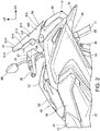
- Fig. 2 is a right-side view of a front part of the motorcycle 1.
- Fig. 3A is a view of the shield 61 and its peripheral configuration viewed from the front side of the vehicle body.
- the front cowl 54 is supported through a bracket (not illustrated) by the head pipe 14 constituting a front part of the body frame F and, as illustrated in Fig. 2 and Fig. 3A , is formed as a cover that covers, from front, the front part of the vehicle body at a position ahead of the head pipe 14 and below the handlebar 26.
- a front surface of the front cowl 54 is formed in a fundamental curved surface that causes a traveling wind from the front side to flow smoothly.
- a front end position (indicated by reference sign ⁇ in Fig. 2 ) set at the vehicle width-wise centre is used as a reference position
- the fundamental curved surface is made as a forward-protruding curved surface that diverges away from the reference position vertically and horizontally toward the rear.
- the front end position ⁇ coincides with a front end of the headlight 60, and the front surface of the front cowl 54 including a front surface of the headlight 60 is formed in the fundamental curved surface.
- the headlight 60 is embedded in the front cowl 54 so as to constitute a part of the front surface of the front cowl 54, so that the fundamental curved surface is formed by the headlight 60 and the front cowl 54.
- the shield 61 is attached to an upper part of the front cowl 54 through a stay member 101 to be described later ( Fig. 5 to be described later).
- reference numeral 102 indicates a fastening member to fasten and fix the shield 61 to the stay member 101 (four fastening bolts in the present configuration).
- the shield 61 is supported on the upper part of the front cowl 54 with a clearance between them at the front. Hence, the shield 61 is away from the fundamental curved surface of the front cowl 54 and does not constitute a part of the fundamental curved surface.
- the shield 61 has the shape of a curve extending horizontally toward the rear and is formed in the shape of a slope tilting upward toward the rear, and is thus formed in a curved surface (hereinafter referred to as a "fundamental curved surface 61W of the shield 61") that causes a wind during traveling to flow to the left and right of the vehicle body.
- the fundamental curved surface 61W of the shield 61 is similar to the front cowl 54 in that it forms a forward-protruding curved surface in a top view ( Fig.
- the fundamental curved surface is formed not in the shape of a forward-protruding curve like the front cowl 54 but in the shape of a straight line extending upward toward the rear.
- the shield 61 and the front cowl 54 are formed symmetrically about the vehicle width-wise centre.
- the shield 61 Since the shield 61 is separated from the fundamental curved surface 61W of the front cowl 54 and tilts upward toward the rear, the shield 61 can be disposed to reach a high position. Thereby, it is possible to cover the front side of the rider sitting behind the front cowl 54 with the shield 61 without forcing the rider to largely lean forward and thus to easily achieve a high windbreak effect, which is suitable for a long distance driving.
- the shield 61 is made as a relatively large shield 61 having a vertical length longer than a horizontal length in the vehicle width-wise direction.
- a lower edge of the shield 61 is located below an upper edge of the front cowl 54 and the handlebar 26, and an upper edge of the shield 61 is located above the handlebar 26, which makes it possible to broadly cover the upper body of an occupant behind the shield 61.
- a transparent resin material is used as a material of the shield 61.
- notch portions 61A are formed in left and right side edges of the shield 61 by notching the side edges inward in the vehicle width-wise direction at a substantially middle position in the vertical direction.
- the left and right notch portions 61A define a shield narrow portion 61S being the narrowest in the vehicle width-wise direction.
- a shield lower portion 61L constituting a part under the shield narrow portion 61S is formed as a first wide portion being the widest
- a shield upper portion 61H being a part over the shield narrow portion 61S is formed as a second wide portion being the second widest after the shield lower portion 61L.
- Fig. 3B illustrates a shield 161 according to a reference example.
- traveling winds flowing toward the left and right of the shield 161 are illustrated.
- the shield 161 is a shield made by removing shield recess portions 61X to be described below from the shield 61 according to the present configuration.
- upper and lower traveling winds along the shield 61 are different in flow velocity; a faster wind W1 is generated in a lower part of the shield 61 and a slower wind W2 is generated in an upper part of the shield 61.
- the joining of these traveling winds W1, W2 different in flow velocity results in generation of a vortex W3.
- the vortex W3 causes wind noise and an increase in air resistance.
- the shield 61 of this embodiment includes, at left and right parts of the shield 61, the recess portions 61X (hereinafter referred to as the "shield recess portions 61X”) being recessed from the fundamental curved surface of the shield 61.
- the shield recess portions 61X introduce a part of a traveling wind, flowing along the fundamental curved surface 61W of the shield 61, into between the traveling winds W1, W2 different in flow velocity, and thereby make it possible to reduce the joining of the traveling winds W1, W2 and reduce the generation of the vortex W3.
- the shield recess portions 61X are arranged at left and right side edges of the shield upper portion 61H, namely, arranged in areas near left and right corner parts made between the shield upper portion 61H and the shield narrow portion 61S.
- the shield recess portions 61X have a vertically long shape extending in an upward direction along the left and right side edges of the shield 61, and each have the shape of a rearward-protruding recess being widened vertically toward the outside in the vehicle width-wise direction.
- Fig. 4A is a sectional view taken along a line IV-IV in Fig. 3A
- Fig. 4B is an enlarged view of a cross section of the shield recess portion 61X illustrated in Fig. 4A .
- the shield recess portions 61X are recess portions (61X) being recessed rearward from the fundamental curved surface 61W of the shield 61 at both left and right ends of the shield 61 and, as illustrated in Fig. 4B , the shield recess portions have a cross-sectional shape where front corner parts of the respective left and right side edges of the shield 61 are cut obliquely.
- the shield recess portions are each formed in the shape of an open groove which becomes deeper rearward toward the outside in the vehicle width-wise direction and whose outer side in the vehicle width-wise direction is open.
- a chain double-dashed line indicates the outline of the shield in the case of no shield recess portions 61X.
- each shield recess portion 61X has the shape of a recess being widened vertically toward the outside in the vehicle width-wise direction, it is possible to spread vertically a traveling wind flowing along the shield recess portion 61X to make it flow more easily, and thus introduce the traveling wind into between the upper and lower traveling winds W1, W2 efficiently. Thereby, the joining of the traveling winds W1, W2 can be reduced efficiently.
- the shield recess portion 61X has the shape of an open groove whose outer side in the vehicle width-wise direction is open, it does not block the flow of a travelling wind flowing along the shield recess portion 61X toward the outside in the vehicle width-wise direction.
- the joining of the traveling winds W1, W2 can be further reduced.
- the generation of the vortex W3 between the traveling winds W1, W2 is reduced and the effect of rectifying the flow of the traveling winds is enhanced.
- the shield 61 and its peripheral configuration will be detailed more.
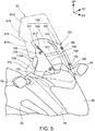
- Fig. 5 is a perspective view in which the shield 61 and its peripheral configuration are viewed from the front right side. Note that, in Fig. 5 , the shield 61 is illustrated in a chain double-dashed line for the sake of convenience.
- Fig. 6 is a sectional side view illustrating the shield 61 and its peripheral configuration. Fig. 6 illustrates a side cross section at the vehicle width-wise centre.
- the stay member 101 having a square U-shaped cross section and standing upward from the upper part of the front cowl 54 is attached between the front cowl 54 and the shield 61.
- the stay member 101 integrally includes: a pair of left and right standing portions 103 that stand upward from the upper part of the front cowl 54 while being spaced from each other in the vehicle width-wise direction; and a bridging plate portion 105 bridging upper parts of the pair of left and right standing portions 103, and a meter 110 is supported in an area surrounded by the pair of left and right standing portions 103 and the bridging plate portion 105. Thereby, the meter 110 is surrounded by the front cowl 54 and the stay member 101.
- the meter 110 is a unit for displaying vehicle information such as a vehicle speed and an engine speed, and is disposed with a display surface 110A of the meter 110 directed obliquely rearward, that is, directed opposed to the rider.
- the bridging plate portion 105 integrally includes: an inclined plate portion 106 extending upward toward the rear in an area between the pair of left and right standing portions 103; and a pair of left and right shield support portions 107 projecting forward and upward of the inclined plate portion 106 and extending upward toward the rear at the left and right of the inclined plate portion 106, and the shield 61 is fastened to front surfaces of the pair of left and right shield support portions 107 with multiple fastening members 102.
- the stay member 101 serves not only as a meter cover covering the meter 110 and a meter stay supporting the meter 110 but also as a shield stay supporting the shield 61.
- the inclined plate portion 106 covers an upper part of the meter 110 and extends further rearward and upward than the meter 110, and thereby serves as a meter visor to protect the meter 110 against the sun.
- the inclined plate portion 106 extends downward toward the front so as to cover an area behind a shield opening 61Y bored in the shield 61, and thus it also serves as a traveling wind guide to guide a traveling wind WC introduced through the shield opening 61Y toward the rear upper side, as illustrated in Fig. 6 .
- the shield opening 61Y is an opening bored at the centre of the shield 61. More specifically, the shield opening is provided at the vehicle width-wise centre of the shield 61 and at a substantially middle position in the vertical direction of the shield, and is formed as a horizontally long opening that is open in a front-rear direction throughout the width of the inclined plate portion 106.
- reference sign WD indicates a traveling wind that flows toward the shield 61 and then flows obliquely upward along the front surface of the shield 61 at a position above the shield opening 61Y
- reference sign WE indicates a traveling wind that flows above the shield 61.
- the traveling wind WD flowing upward along an upper surface of the shield 61 can bring about an effect of pushing upward the streamline of the traveling wind WE flowing above the shield 61 (a traveling wind push-up effect illustrated by reference sign Y in Fig. 6 ).
- the traveling wind WC that has entered the shield opening 61Y and flows along an upper surface of the inclined plate portion 106 as the meter visor can also push upward the streamline of the traveling wind WE flowing above the shield 61, as illustrated in Fig. 6 .
- the traveling wind WC having entered the shield opening 61Y can be dispersed to the left and right through a pair of left and right openings 61Z that are bored in the inclined plate portion 106 as the meter visor while being spaced from each other in the vehicle width-wise direction. Owing to these, in the present configuration, it is possible to maintain turning performance while achieving the same windbreak effect as a taller shield.
- the pair of left and right openings 61Z (hereinafter referred to as "stay-side openings 61Z”) is arranged above the shield opening 61Y in the inclined plate portion 106 while being spaced from each other in the vehicle width-wise direction.
- the stay-side openings 61Z are openings to cause the traveling wind W1 having entered the shield opening 61Y to flow outward in the vehicle width-wise direction.
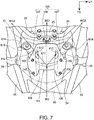
- Fig. 7 is a view of the stay member 101 and its peripheral configuration viewed from the upper side. Note that, Fig. 7 also illustrates the shield 61 in a chain double-dashed line.
- the pair of left and right stay-side openings 61Z is arranged in a pair of left and right wall portions 109 that connect steps between the inclined plate portion 106 and the pair of left and right shield support portions 107.
- the wall portions 109 are formed in inclined walls standing forward and upward from the inclined plate portion 106 and being stretched outward in the vehicle width-wise direction toward the front upper side. Since the stay-side openings 61Z are open in the wall portions 109 being inclined walls, the stay-side openings 61Z are openings being open in the vehicle width-wise (horizontal) direction in the bridging plate portion 105.
- the traveling wind WC having entered the shield opening 61Y can be split into three, i.e., a traveling wind WC1 flowing between the left and right stay-side openings 61Z and traveling winds WC2, WC3 flowing through the respective left and right stay-side openings 61Z.
- the traveling wind may be still retained at the vehicle width-wise centre and this may degrade the turning performance; however, since the traveling wind is also dispersed horizontally, this is also favourable for enhancement in turning performance.
- the shield 61 that is provided on the upper part of the front cowl 54 with a clearance between them is formed along the fundamental curved surface 61W that causes a wind during traveling to flow to the left and right of the vehicle body, and the shield recess portions 61X being recessed from the fundamental curved surface 61W are arranged at the left and right parts of the shield 61.
- the shield recess portions 61X being recessed from the fundamental curved surface 61W are arranged at the left and right parts of the shield 61.
- the shield 61 is provided with the shield narrow portion 61S where the shield is narrowed in the vehicle width-wise direction by the notch portions 61A formed by notching the shield inward in the vehicle width-wise direction, and the shield recess portions 61X are located above the notch portions 61A.
- the shield narrow portion 61S where the shield is narrowed in the vehicle width-wise direction by the notch portions 61A formed by notching the shield inward in the vehicle width-wise direction, and the shield recess portions 61X are located above the notch portions 61A.
- the shield 61 has the shield opening 61Y being open at the vehicle width-wise centre in the shield narrow portion 61S.
- the air volume of the traveling wind W1 to flow to the left and right from the shield narrow portion 61S is reduced and the joining of the traveling winds W1, W2 can be further suppressed accordingly, which further facilitates suppression of wind noise and the like.
- a traveling wind from the front side partially passes through the shield opening 61Y, and air resistance can be reduced accordingly.
- the shield 61 is supported by the stay member 101 serving as, for example, a meter stay supporting the meter 110, and the stay member 101 integrally includes the inclined plate portion 106 serving as a meter visor covering the meter 110 from above.
- the stay member 101 has the function to support the meter 110, the function as the meter visor, and the function to support the shield 61. This can reduce the number of components as compared to the case where these functions are implemented by separate components.
- the stay member 101 is located behind the shield opening 61Y, and an upper surface of the stay member 101 is formed in a shape that causes a wind having flowed through the shield opening 61Y to flow upward.
- the traveling wind WC flowing along the upper surface of the stay member 101 can also push upward the streamline of the traveling wind WE flowing above the shield 61.
- the effect of pushing upward the traveling wind WE flowing above the shield 61 can be further enhanced, achieving the same windbreak effect as a taller shield.
- the stay-side openings 61Z to cause a wind having flowed through the shield opening 61Y to flow to the left and right are arranged at left and right parts of the stay member 101.
- a wind having flowed through the shield opening 61Y is dispersed to the left and right, which can reduce the power of wind blowing against the arms of the rider and the like and enhance turning performance. Owing to these, it is possible to maintain turning performance while achieving the same windbreak effect as a taller shield.
- the above embodiment describes the case where the present invention is applied to the motorcycle 1 illustrated in Fig. 1 .
- the present invention may be applied to other publicly-known straddle-type vehicles.
- the straddle-type vehicles encompass all kinds of vehicles on which a rider rides by straddling a vehicle body, and includes not only motorcycles (including motor bicycles) but also three-wheeled vehicles and four-wheeled vehicles such as all-terrain vehicles (ATVs).
Landscapes
- Engineering & Computer Science (AREA)
- Mechanical Engineering (AREA)
- Automatic Cycles, And Cycles In General (AREA)
- Instrument Panels (AREA)
Claims (1)
- Vorderstruktur für ein Grätschsitztyp-Fahrzeug, mit: einer Abdeckung (54), die einen vorderen Teil einer Fahrzeugkarosserie bedeckt; und einem Schutzschild (61), das an einem oberen Teil der Abdeckung (54) mit einem Freiraum dazwischen vorgesehen ist, bei der
das Schutzschild (61) entlang einer gebogenen Grundfläche (61W) ausgebildet ist, die bewirkt, dass ein Wind während einem Fahren nach links und rechts der Fahrzeugkarosserie strömt,
das Schutzschild (61) von einem Zählerständer (101), der einen Zähler (110) abstützt, gestützt wird,
der Zählerständer (101) integral einen Zählerschirm (106), der den Zähler (110) von oben bedeckt, aufweist und sich hinter der Schutzschildöffnung (61Y) befindet, und
eine obere Fläche des Zählerständers (101) in einer Form ausgebildet ist, die bewirkt, dass ein Wind, der durch eine Schildöffnung (61Y) geströmt ist, nach oben strömt;
wobei die Vorderstruktur dadurch gekennzeichnet ist, dass
das Schutzschild (61) mit einem engen Bereich (61S) versehen ist, wo das Schutzschild in einer Fahrzeugbreitenrichtung durch Einkerbungsbereiche (61A) verengt ist, die durch Einkerben des Schutzschildes in der Fahrzeugbreitenrichtung nach innen ausgebildet sind,
das Schutzschild (61) eine Schildöffnung (61Y) aufweist, die in einer fahrzeugbreitenweisen Mitte in dem verengten Bereich (61S) offen ist,
Aussparungsbereiche (61X), die von der gekrümmten Grundfläche (61W) ausgespart sind, an einem linken und rechten Teil des Schutzschilds (61) angeordnet sind und dass ständerseitige Öffnungen (61Z) zum Bewirken, dass ein Wind durch die Schildöffnung (61Y) zum Strömen nach links und rechts hindurchströmt, an einem linken und rechten Teil des Zählerständers (101) angeordnet sind, und dass
die Aussparungsbereiche (61X) sich oberhalb der Einkerbungsbereiche (61A) befinden.
Applications Claiming Priority (1)
| Application Number | Priority Date | Filing Date | Title |
|---|---|---|---|
| JP2015029991A JP6129888B2 (ja) | 2015-02-18 | 2015-02-18 | 鞍乗り型車両の前部構造 |
Publications (2)
| Publication Number | Publication Date |
|---|---|
| EP3059149A1 EP3059149A1 (de) | 2016-08-24 |
| EP3059149B1 true EP3059149B1 (de) | 2018-12-05 |
Family
ID=55353093
Family Applications (1)
| Application Number | Title | Priority Date | Filing Date |
|---|---|---|---|
| EP16155380.5A Active EP3059149B1 (de) | 2015-02-18 | 2016-02-12 | Vorderstruktur eines grätschsitzfahrzeugs |
Country Status (4)
| Country | Link |
|---|---|
| EP (1) | EP3059149B1 (de) |
| JP (1) | JP6129888B2 (de) |
| BR (1) | BR102016003183B1 (de) |
| ES (1) | ES2713675T3 (de) |
Families Citing this family (5)
| Publication number | Priority date | Publication date | Assignee | Title |
|---|---|---|---|---|
| JP6001615B2 (ja) * | 2014-09-30 | 2016-10-05 | 本田技研工業株式会社 | 鞍乗り型車両 |
| JP6277526B2 (ja) * | 2015-03-30 | 2018-02-14 | 本田技研工業株式会社 | 鞍乗り型車両の走行風取り入れ構造 |
| JP7225632B2 (ja) | 2018-09-21 | 2023-02-21 | スズキ株式会社 | 鞍乗型車両のフロント構造 |
| JP7187598B2 (ja) * | 2021-03-15 | 2022-12-12 | 本田技研工業株式会社 | 鞍乗り型車両のスクリーン固定構造 |
| JP7519971B2 (ja) * | 2021-09-07 | 2024-07-22 | 本田技研工業株式会社 | スクリーン |
Family Cites Families (11)
| Publication number | Priority date | Publication date | Assignee | Title |
|---|---|---|---|---|
| AU8412282A (en) * | 1981-07-09 | 1983-01-13 | Bertrand Cadart | Windshield for motorcycle |
| JP2688913B2 (ja) * | 1988-03-11 | 1997-12-10 | 本田技研工業株式会社 | 自動二輪車のウインドスクリーン装置 |
| JP3245921B2 (ja) | 1992-01-28 | 2002-01-15 | スズキ株式会社 | 自動2輪車のカウリング |
| JPH1035563A (ja) * | 1996-07-25 | 1998-02-10 | Yamaha Motor Co Ltd | 自動二輪車の風防スクリーン |
| DE10230915A1 (de) * | 2002-07-09 | 2004-01-22 | Bayerische Motoren Werke Ag | Verstellbares Windschild |
| WO2008082357A1 (en) * | 2007-01-02 | 2008-07-10 | Snowolverine Ab | An arrangement in a windscreen |
| JP2010070107A (ja) * | 2008-09-19 | 2010-04-02 | Honda Motor Co Ltd | ウインドスクリーン取付構造 |
| JP5492717B2 (ja) * | 2010-09-16 | 2014-05-14 | 川崎重工業株式会社 | 自動二輪車のウィンドスクリーン |
| JP5551567B2 (ja) * | 2010-10-29 | 2014-07-16 | 本田技研工業株式会社 | 鞍乗り型車両の前部構造 |
| JP5988639B2 (ja) * | 2012-03-22 | 2016-09-07 | 本田技研工業株式会社 | 鞍乗り型車両の導風構造 |
| JP6001615B2 (ja) * | 2014-09-30 | 2016-10-05 | 本田技研工業株式会社 | 鞍乗り型車両 |
-
2015
- 2015-02-18 JP JP2015029991A patent/JP6129888B2/ja not_active Expired - Fee Related
-
2016
- 2016-02-12 EP EP16155380.5A patent/EP3059149B1/de active Active
- 2016-02-12 ES ES16155380T patent/ES2713675T3/es active Active
- 2016-02-16 BR BR102016003183-4A patent/BR102016003183B1/pt active IP Right Grant
Non-Patent Citations (1)
| Title |
|---|
| None * |
Also Published As
| Publication number | Publication date |
|---|---|
| JP6129888B2 (ja) | 2017-05-17 |
| JP2016150707A (ja) | 2016-08-22 |
| ES2713675T3 (es) | 2019-05-23 |
| EP3059149A1 (de) | 2016-08-24 |
| BR102016003183A2 (pt) | 2016-10-18 |
| BR102016003183B1 (pt) | 2022-11-08 |
Similar Documents
| Publication | Publication Date | Title |
|---|---|---|
| CN101016063B (zh) | 摩托车 | |
| JP5988639B2 (ja) | 鞍乗り型車両の導風構造 | |
| EP3059149A1 (de) | Vorderstruktur eines grätschsitzfahrzeugs | |
| US9764789B2 (en) | Side cover structure of saddle-ride-type vehicle | |
| US7325853B2 (en) | Arrangement structure of upper cowl, screen, and meter for motorcycles | |
| EP3141464B1 (de) | Hinterer kotflügel für ein motorrad | |
| JP5576308B2 (ja) | 鞍乗り型車両 | |
| JP5700676B2 (ja) | 鞍乗型車両の外装部品 | |
| JP2016135655A (ja) | 鞍乗り型車両 | |
| US9581073B2 (en) | Radiator structure for two-wheeled vehicle | |
| EP2543581B1 (de) | Verkleidungsstruktur für ein Fahrzeug mit Sattel | |
| JP2009173216A (ja) | 鞍乗り型車両のシート構造 | |
| JP6103987B2 (ja) | 鞍乗り型車両の前方構造 | |
| JP7328290B2 (ja) | 鞍乗り型車両 | |
| JP2013067182A (ja) | 鞍乗型車両 | |
| JP6773715B2 (ja) | 鞍乗り型車両 | |
| JP6682410B2 (ja) | 鞍乗型車両の冷却水リザーバタンク | |
| EP3141466B1 (de) | Sattelfahrzeug | |
| JP7692970B2 (ja) | 鞍乗型車両 | |
| JP7450773B2 (ja) | 鞍乗り型車両 | |
| JP2025136687A (ja) | 鞍乗型車両 | |
| JP2001225773A (ja) | スクータ型自動二輪車の荷物収納室 | |
| CN118419184A (zh) | 车把罩结构 | |
| JP2021030800A (ja) | 鞍乗型車両 | |
| JPH03136985A (ja) | 自動2輪車 |
Legal Events
| Date | Code | Title | Description |
|---|---|---|---|
| PUAI | Public reference made under article 153(3) epc to a published international application that has entered the european phase |
Free format text: ORIGINAL CODE: 0009012 |
|
| AK | Designated contracting states |
Kind code of ref document: A1 Designated state(s): AL AT BE BG CH CY CZ DE DK EE ES FI FR GB GR HR HU IE IS IT LI LT LU LV MC MK MT NL NO PL PT RO RS SE SI SK SM TR |
|
| AX | Request for extension of the european patent |
Extension state: BA ME |
|
| STAA | Information on the status of an ep patent application or granted ep patent |
Free format text: STATUS: REQUEST FOR EXAMINATION WAS MADE |
|
| 17P | Request for examination filed |
Effective date: 20170222 |
|
| RBV | Designated contracting states (corrected) |
Designated state(s): AL AT BE BG CH CY CZ DE DK EE ES FI FR GB GR HR HU IE IS IT LI LT LU LV MC MK MT NL NO PL PT RO RS SE SI SK SM TR |
|
| STAA | Information on the status of an ep patent application or granted ep patent |
Free format text: STATUS: EXAMINATION IS IN PROGRESS |
|
| 17Q | First examination report despatched |
Effective date: 20180104 |
|
| GRAP | Despatch of communication of intention to grant a patent |
Free format text: ORIGINAL CODE: EPIDOSNIGR1 |
|
| STAA | Information on the status of an ep patent application or granted ep patent |
Free format text: STATUS: GRANT OF PATENT IS INTENDED |
|
| INTG | Intention to grant announced |
Effective date: 20180612 |
|
| GRAS | Grant fee paid |
Free format text: ORIGINAL CODE: EPIDOSNIGR3 |
|
| GRAA | (expected) grant |
Free format text: ORIGINAL CODE: 0009210 |
|
| STAA | Information on the status of an ep patent application or granted ep patent |
Free format text: STATUS: THE PATENT HAS BEEN GRANTED |
|
| AK | Designated contracting states |
Kind code of ref document: B1 Designated state(s): AL AT BE BG CH CY CZ DE DK EE ES FI FR GB GR HR HU IE IS IT LI LT LU LV MC MK MT NL NO PL PT RO RS SE SI SK SM TR |
|
| RAP1 | Party data changed (applicant data changed or rights of an application transferred) |
Owner name: HONDA MOTOR CO., LTD. |
|
| REG | Reference to a national code |
Ref country code: GB Ref legal event code: FG4D |
|
| REG | Reference to a national code |
Ref country code: CH Ref legal event code: EP |
|
| REG | Reference to a national code |
Ref country code: AT Ref legal event code: REF Ref document number: 1072674 Country of ref document: AT Kind code of ref document: T Effective date: 20181215 |
|
| REG | Reference to a national code |
Ref country code: IE Ref legal event code: FG4D |
|
| REG | Reference to a national code |
Ref country code: DE Ref legal event code: R096 Ref document number: 602016007693 Country of ref document: DE |
|
| REG | Reference to a national code |
Ref country code: NL Ref legal event code: MP Effective date: 20181205 |
|
| REG | Reference to a national code |
Ref country code: AT Ref legal event code: MK05 Ref document number: 1072674 Country of ref document: AT Kind code of ref document: T Effective date: 20181205 |
|
| REG | Reference to a national code |
Ref country code: LT Ref legal event code: MG4D |
|
| PG25 | Lapsed in a contracting state [announced via postgrant information from national office to epo] |
Ref country code: LV Free format text: LAPSE BECAUSE OF FAILURE TO SUBMIT A TRANSLATION OF THE DESCRIPTION OR TO PAY THE FEE WITHIN THE PRESCRIBED TIME-LIMIT Effective date: 20181205 Ref country code: LT Free format text: LAPSE BECAUSE OF FAILURE TO SUBMIT A TRANSLATION OF THE DESCRIPTION OR TO PAY THE FEE WITHIN THE PRESCRIBED TIME-LIMIT Effective date: 20181205 Ref country code: NO Free format text: LAPSE BECAUSE OF FAILURE TO SUBMIT A TRANSLATION OF THE DESCRIPTION OR TO PAY THE FEE WITHIN THE PRESCRIBED TIME-LIMIT Effective date: 20190305 Ref country code: AT Free format text: LAPSE BECAUSE OF FAILURE TO SUBMIT A TRANSLATION OF THE DESCRIPTION OR TO PAY THE FEE WITHIN THE PRESCRIBED TIME-LIMIT Effective date: 20181205 Ref country code: FI Free format text: LAPSE BECAUSE OF FAILURE TO SUBMIT A TRANSLATION OF THE DESCRIPTION OR TO PAY THE FEE WITHIN THE PRESCRIBED TIME-LIMIT Effective date: 20181205 Ref country code: BG Free format text: LAPSE BECAUSE OF FAILURE TO SUBMIT A TRANSLATION OF THE DESCRIPTION OR TO PAY THE FEE WITHIN THE PRESCRIBED TIME-LIMIT Effective date: 20190305 Ref country code: HR Free format text: LAPSE BECAUSE OF FAILURE TO SUBMIT A TRANSLATION OF THE DESCRIPTION OR TO PAY THE FEE WITHIN THE PRESCRIBED TIME-LIMIT Effective date: 20181205 |
|
| PGFP | Annual fee paid to national office [announced via postgrant information from national office to epo] |
Ref country code: IT Payment date: 20190228 Year of fee payment: 4 |
|
| REG | Reference to a national code |
Ref country code: ES Ref legal event code: FG2A Ref document number: 2713675 Country of ref document: ES Kind code of ref document: T3 Effective date: 20190523 |
|
| PG25 | Lapsed in a contracting state [announced via postgrant information from national office to epo] |
Ref country code: GR Free format text: LAPSE BECAUSE OF FAILURE TO SUBMIT A TRANSLATION OF THE DESCRIPTION OR TO PAY THE FEE WITHIN THE PRESCRIBED TIME-LIMIT Effective date: 20190306 Ref country code: SE Free format text: LAPSE BECAUSE OF FAILURE TO SUBMIT A TRANSLATION OF THE DESCRIPTION OR TO PAY THE FEE WITHIN THE PRESCRIBED TIME-LIMIT Effective date: 20181205 Ref country code: AL Free format text: LAPSE BECAUSE OF FAILURE TO SUBMIT A TRANSLATION OF THE DESCRIPTION OR TO PAY THE FEE WITHIN THE PRESCRIBED TIME-LIMIT Effective date: 20181205 Ref country code: RS Free format text: LAPSE BECAUSE OF FAILURE TO SUBMIT A TRANSLATION OF THE DESCRIPTION OR TO PAY THE FEE WITHIN THE PRESCRIBED TIME-LIMIT Effective date: 20181205 |
|
| PGFP | Annual fee paid to national office [announced via postgrant information from national office to epo] |
Ref country code: FR Payment date: 20190228 Year of fee payment: 4 |
|
| PG25 | Lapsed in a contracting state [announced via postgrant information from national office to epo] |
Ref country code: NL Free format text: LAPSE BECAUSE OF FAILURE TO SUBMIT A TRANSLATION OF THE DESCRIPTION OR TO PAY THE FEE WITHIN THE PRESCRIBED TIME-LIMIT Effective date: 20181205 |
|
| PG25 | Lapsed in a contracting state [announced via postgrant information from national office to epo] |
Ref country code: PL Free format text: LAPSE BECAUSE OF FAILURE TO SUBMIT A TRANSLATION OF THE DESCRIPTION OR TO PAY THE FEE WITHIN THE PRESCRIBED TIME-LIMIT Effective date: 20181205 Ref country code: CZ Free format text: LAPSE BECAUSE OF FAILURE TO SUBMIT A TRANSLATION OF THE DESCRIPTION OR TO PAY THE FEE WITHIN THE PRESCRIBED TIME-LIMIT Effective date: 20181205 Ref country code: PT Free format text: LAPSE BECAUSE OF FAILURE TO SUBMIT A TRANSLATION OF THE DESCRIPTION OR TO PAY THE FEE WITHIN THE PRESCRIBED TIME-LIMIT Effective date: 20190405 |
|
| PGFP | Annual fee paid to national office [announced via postgrant information from national office to epo] |
Ref country code: ES Payment date: 20190528 Year of fee payment: 4 |
|
| PG25 | Lapsed in a contracting state [announced via postgrant information from national office to epo] |
Ref country code: IS Free format text: LAPSE BECAUSE OF FAILURE TO SUBMIT A TRANSLATION OF THE DESCRIPTION OR TO PAY THE FEE WITHIN THE PRESCRIBED TIME-LIMIT Effective date: 20190405 Ref country code: RO Free format text: LAPSE BECAUSE OF FAILURE TO SUBMIT A TRANSLATION OF THE DESCRIPTION OR TO PAY THE FEE WITHIN THE PRESCRIBED TIME-LIMIT Effective date: 20181205 Ref country code: SM Free format text: LAPSE BECAUSE OF FAILURE TO SUBMIT A TRANSLATION OF THE DESCRIPTION OR TO PAY THE FEE WITHIN THE PRESCRIBED TIME-LIMIT Effective date: 20181205 Ref country code: EE Free format text: LAPSE BECAUSE OF FAILURE TO SUBMIT A TRANSLATION OF THE DESCRIPTION OR TO PAY THE FEE WITHIN THE PRESCRIBED TIME-LIMIT Effective date: 20181205 Ref country code: SK Free format text: LAPSE BECAUSE OF FAILURE TO SUBMIT A TRANSLATION OF THE DESCRIPTION OR TO PAY THE FEE WITHIN THE PRESCRIBED TIME-LIMIT Effective date: 20181205 |
|
| REG | Reference to a national code |
Ref country code: DE Ref legal event code: R097 Ref document number: 602016007693 Country of ref document: DE |
|
| REG | Reference to a national code |
Ref country code: CH Ref legal event code: PL |
|
| PLBE | No opposition filed within time limit |
Free format text: ORIGINAL CODE: 0009261 |
|
| STAA | Information on the status of an ep patent application or granted ep patent |
Free format text: STATUS: NO OPPOSITION FILED WITHIN TIME LIMIT |
|
| PG25 | Lapsed in a contracting state [announced via postgrant information from national office to epo] |
Ref country code: MC Free format text: LAPSE BECAUSE OF FAILURE TO SUBMIT A TRANSLATION OF THE DESCRIPTION OR TO PAY THE FEE WITHIN THE PRESCRIBED TIME-LIMIT Effective date: 20181205 Ref country code: LU Free format text: LAPSE BECAUSE OF NON-PAYMENT OF DUE FEES Effective date: 20190212 Ref country code: DK Free format text: LAPSE BECAUSE OF FAILURE TO SUBMIT A TRANSLATION OF THE DESCRIPTION OR TO PAY THE FEE WITHIN THE PRESCRIBED TIME-LIMIT Effective date: 20181205 Ref country code: SI Free format text: LAPSE BECAUSE OF FAILURE TO SUBMIT A TRANSLATION OF THE DESCRIPTION OR TO PAY THE FEE WITHIN THE PRESCRIBED TIME-LIMIT Effective date: 20181205 |
|
| 26N | No opposition filed |
Effective date: 20190906 |
|
| REG | Reference to a national code |
Ref country code: BE Ref legal event code: MM Effective date: 20190228 |
|
| REG | Reference to a national code |
Ref country code: IE Ref legal event code: MM4A |
|
| REG | Reference to a national code |
Ref country code: DE Ref legal event code: R084 Ref document number: 602016007693 Country of ref document: DE |
|
| PG25 | Lapsed in a contracting state [announced via postgrant information from national office to epo] |
Ref country code: LI Free format text: LAPSE BECAUSE OF NON-PAYMENT OF DUE FEES Effective date: 20190228 Ref country code: CH Free format text: LAPSE BECAUSE OF NON-PAYMENT OF DUE FEES Effective date: 20190228 |
|
| PG25 | Lapsed in a contracting state [announced via postgrant information from national office to epo] |
Ref country code: IE Free format text: LAPSE BECAUSE OF NON-PAYMENT OF DUE FEES Effective date: 20190212 |
|
| PG25 | Lapsed in a contracting state [announced via postgrant information from national office to epo] |
Ref country code: BE Free format text: LAPSE BECAUSE OF NON-PAYMENT OF DUE FEES Effective date: 20190228 |
|
| PG25 | Lapsed in a contracting state [announced via postgrant information from national office to epo] |
Ref country code: TR Free format text: LAPSE BECAUSE OF FAILURE TO SUBMIT A TRANSLATION OF THE DESCRIPTION OR TO PAY THE FEE WITHIN THE PRESCRIBED TIME-LIMIT Effective date: 20181205 |
|
| PG25 | Lapsed in a contracting state [announced via postgrant information from national office to epo] |
Ref country code: MT Free format text: LAPSE BECAUSE OF NON-PAYMENT OF DUE FEES Effective date: 20190212 |
|
| GBPC | Gb: european patent ceased through non-payment of renewal fee |
Effective date: 20200212 |
|
| PG25 | Lapsed in a contracting state [announced via postgrant information from national office to epo] |
Ref country code: GB Free format text: LAPSE BECAUSE OF NON-PAYMENT OF DUE FEES Effective date: 20200212 Ref country code: FR Free format text: LAPSE BECAUSE OF NON-PAYMENT OF DUE FEES Effective date: 20200229 |
|
| PG25 | Lapsed in a contracting state [announced via postgrant information from national office to epo] |
Ref country code: CY Free format text: LAPSE BECAUSE OF FAILURE TO SUBMIT A TRANSLATION OF THE DESCRIPTION OR TO PAY THE FEE WITHIN THE PRESCRIBED TIME-LIMIT Effective date: 20181205 |
|
| PG25 | Lapsed in a contracting state [announced via postgrant information from national office to epo] |
Ref country code: HU Free format text: LAPSE BECAUSE OF FAILURE TO SUBMIT A TRANSLATION OF THE DESCRIPTION OR TO PAY THE FEE WITHIN THE PRESCRIBED TIME-LIMIT; INVALID AB INITIO Effective date: 20160212 |
|
| PG25 | Lapsed in a contracting state [announced via postgrant information from national office to epo] |
Ref country code: ES Free format text: LAPSE BECAUSE OF NON-PAYMENT OF DUE FEES Effective date: 20200213 |
|
| PG25 | Lapsed in a contracting state [announced via postgrant information from national office to epo] |
Ref country code: IT Free format text: LAPSE BECAUSE OF NON-PAYMENT OF DUE FEES Effective date: 20200212 |
|
| PG25 | Lapsed in a contracting state [announced via postgrant information from national office to epo] |
Ref country code: MK Free format text: LAPSE BECAUSE OF FAILURE TO SUBMIT A TRANSLATION OF THE DESCRIPTION OR TO PAY THE FEE WITHIN THE PRESCRIBED TIME-LIMIT Effective date: 20181205 |
|
| PGFP | Annual fee paid to national office [announced via postgrant information from national office to epo] |
Ref country code: DE Payment date: 20260121 Year of fee payment: 11 |