EP3060708B1 - Métier à tricoter circulaire à mécanisme de mise en prise et de libération de prise de la plaque à crochets du groupe plateau - Google Patents
Métier à tricoter circulaire à mécanisme de mise en prise et de libération de prise de la plaque à crochets du groupe plateau Download PDFInfo
- Publication number
- EP3060708B1 EP3060708B1 EP14789411.7A EP14789411A EP3060708B1 EP 3060708 B1 EP3060708 B1 EP 3060708B1 EP 14789411 A EP14789411 A EP 14789411A EP 3060708 B1 EP3060708 B1 EP 3060708B1
- Authority
- EP
- European Patent Office
- Prior art keywords
- engaging
- flange
- hook plate
- pulley
- rotation
- Prior art date
- Legal status (The legal status is an assumption and is not a legal conclusion. Google has not performed a legal analysis and makes no representation as to the accuracy of the status listed.)
- Active
Links
Images


Classifications
-
- D—TEXTILES; PAPER
- D04—BRAIDING; LACE-MAKING; KNITTING; TRIMMINGS; NON-WOVEN FABRICS
- D04B—KNITTING
- D04B15/00—Details of, or auxiliary devices incorporated in, weft knitting machines, restricted to machines of this kind
- D04B15/94—Driving-gear not otherwise provided for
-
- D—TEXTILES; PAPER
- D04—BRAIDING; LACE-MAKING; KNITTING; TRIMMINGS; NON-WOVEN FABRICS
- D04B—KNITTING
- D04B9/00—Circular knitting machines with independently-movable needles
- D04B9/06—Circular knitting machines with independently-movable needles with needle cylinder and dial for ribbed goods
Definitions
- the present invention relates to a circular knitting machine.
- the invention relates to a circular knitting machine characterised by an engaging and disengaging mechanism of the rotation of the hook plate of the dial group with respect to the rotation of the needle cylinder.
- the present invention relates to the technical sector of circular knitting machines, seamless type machines, hosiery machines and the like.
- the term "knitting machine” is meant in general to relate to a circular knitting machine for production of textile articles and provided with a plurality of thread feeding points, in which the thread is supplied to the needles of the machine.
- the knitting machine can be for example of a single-bed or a double-bed type.
- Circular knitting machines can comprise a variable number of thread feeders, for example 2, 4, 6, 8 or more.
- dial group is intended to mean a portion of the knitting machine arranged superiorly of the needle-bearing organ and provided with organs and devices able to cooperate with the needles of the knitting machine and with the threads present in the thread feeders so as to enable production of fabric.
- the dial group In the sector of circular knitting machines, various types of realization of the dial group are known, together with the devices connected thereto.
- the dial group is typically provided with a fixed support plate (or ring), mounted to the bearing structure of the knitting machine, a transport and cutting organ of the threads (known in the sector as a cutter) mounted externally of the support ring so as to be able to rotate about it, and a plurality of pneumatic devices positioned on the support plate.
- the plurality of pneumatic devices usually comprises at least a hook control group provided with one or more command cams, able to interact with the hooks of the knitting machine, and a plurality of pliers groups, equal in number to the feeders of the machine; each pliers group comprises one or more mobile pliers, able to retain or block a thread supplied to the needles of the knitting machine, and the pneumatic actuators moving the pliers.
- the dial group can further comprise cutting devices, each provided with a pneumatically-activated cutting organ able to cooperate with the cutter so as to carry out the cut of the threads transported by the cutter.
- the dial group can comprise thread-aspirating devices which aspirate the threads of one or more feeders and the relative fluff.
- the dial group comprises internally thereof a grouping of numerous devices, some modularly repeated for each thread feeder, others shared among a plurality of feeders, or present singly.
- the dial group further comprises a hook support organ, or "hook plate", bearing a plurality of hooks.
- the hook plate is mounted to the support plate so as to be able to rotate about a rotation axis coinciding with the rotation axis of the needle cylinder.
- the cutter is further solidly constrained to the hook plate, and rotates together therewith.
- Known knitting machines further comprise transmission means which carry out the function of transmitting to the hook plate the rotation generated for the needle cylinder.
- the transmission means typically comprise pairs of pulleys, transmission belts and auxiliary shafts that transmit - synchronously - to the hook plate the rotation generated by a motor moving the needle cylinder.
- These operations can comprise, for example, verification of the stitches formed and under formation on the needle cylinder, the manual detachment of the stitching produced by the needles, the replacement of broken needles or other broken components, etc.
- the dial group draws the threads held by the underlying thread guide feeders of the knitting machine: therefore the threads remain interposed and suspended between the cylinder and the dial group in the vertical space which is created by raising the dial group.
- the whole dial group (comprising hook plate and cutter) is raised and does not need to be in rotation, while the underlying needle cylinder must be able to be rotated in order to carry out the above-mentioned operations.
- the drive transmission is located between the needle cylinder and the hook plate, the hook plate too (though the dial group is raised) continues to rotate synchronously with the underlying cylinder. This leads to some significant drawbacks, as:
- the maintenance configuration included, in some known machines, the limitation to a slow velocity (slow mode) of the needle cylinder, with rotation activated by hand by the operator, for example with a crank.
- Concerning, on the other hand, the problem of undesired cutting of the threads in some known machines the operator first cuts the suspended threads, positioning them internally of the cylinder, preventing the cut by the rotating cutter also in the maintenance configuration.
- machines which exhibit disengaging mechanisms of the cutter which enable, when the dial group is brought into the raised position in order to carry out maintenance, interrupting or disengaging the transmission of drive from the needle cylinder to the cutter (or the hook plate bearing the cutter): in this way the needle cylinder can continue to rotate, while the cutter remains stationary.
- some known machines enable raising, and then lowering, the dial group only in determined angular positions.
- the operator brings the cylinder into a determined angular position in which the "release" of the hook plate is enabled, raises the dial group, performs the maintenance (freely rotating the needle cylinder without the hook plate rotating) and then returns - necessarily - the cylinder exactly into the same angular position in which the dial group had been raised, then to proceed with the lowering thereof and then carrying on with the knitting.
- This solution enables being sure, when the dial group is lowered, that the dial group is synchronised with the needle cylinder.
- this solution also presents some drawbacks:
- the aim underpinning the present invention in its various aspects and/or embodiments, is to disclose a circular knitting machine that is able to obviate one or more of the mentioned drawbacks.
- a further aim of the present invention is to provide a knitting machine characterised by an effective engaging and disengaging system of the dial group (i.e. the rotation of the hook plate and the cutter) with respect to the rotation of the needle cylinder.
- a further aim of the present invention is to provide a knitting machine enabling carrying-out maintenance operations simply and/or rapidly.
- a further aim of the present invention is to provide a knitting machine able to guarantee a correct synchronising between the needle cylinder and the dial group (in particular the hook plate and the cutter) in any operating condition, and in particular following a maintenance operation performed on the needle cylinder.
- a further aim of the present invention is to provide a knitting machine characterised by a high functioning reliability and/or by a low predisposition to faults and malfunctioning.
- a further aim of the present invention is to provide a knitting machine characterised by a simple and rational structure, in particular as concerns the engaging and disengaging system of the dial group.
- a further aim of the present invention is to provide a knitting machine characterised by a realisation cost that is modest with respect to the performance and quality it provides.
- Patent US4339932 describes a machine for knitting a tubular fabric, in particular stocking articles, comprising a needle cylinder, a cylinder holder, a dial, suction and discharge ducts for the produced tubular fabric and means for driving the cylinder holder.
- Patent US3974663 describes an arrangement in a circular hosiery machine in which a motion drive device is provided between the needle cylinder and the dial.
- a program chain advances with each revolution, and a program drum advances intermittently with the action of the chain.
- a clutch couples and disengages two members of the drive between the cylinder and the dial, and a control of the clutch is made dependent on the program chain.
- the rotational motion of the dial is interrupted when the members thereof are not required, and an engagement is provided in at least one predetermined relative angular position.
- the invention relates to a circular knitting machine for knitwear or hosiery, comprising:
- the knitting machine comprises rotation transmission means, housed in the bearing structure and operatively interposed between the needle cylinder and the dial group, configured for transmitting a rotation, generated by said rotation means of the cylinder, synchronously with the hook plate, such that a determined rotation of the hook plate corresponds to a same rotation of the needle cylinder.
- the rotation transmission means comprise:
- the engaging mechanism comprises at least an engaging organ movable, between the pulley and the flange, in a direction which is parallel to, or transversally or perpendicularly intersecting, the first rotation axis of the pulley and the flange, between at least an engaged position and a disengaged position so as to determine passage of the engaged mechanism respectively between the engaged position and the disengaged position.
- the engaging mechanism comprises actuating means operatively active on the engaging organ and configured for enabling the passage of the engaging mechanism from the engaged configuration to the disengaged configuration in any angular position assumed by the flange or the pulley, and for determining the passage of the engaging mechanism from the disengaged configuration to the engaged configuration exclusively with the engaging organ positioned at a predetermined and limited number of angular engaging and disengaging positions defined on the flange or the pulley.
- a number of angular engaging and disengaging positions are defined which are fewer than four or four and/or fewer than two or two and/or wherein, preferably, on the flange or pulley, one and one only angular engaging and disengaging position is defined.
- the engaging organ is mobile, between the pulley and the flange, in a substantially radial direction with respect to the first rotation axis, i.e. substantially perpendicular to, and intersecting the, first rotation axis of the pulley and the flange.
- the engaging organ is movable on a substantially horizontal plane.
- the pulley rotates about a rotation axis coinciding with the rotation axis of the needle cylinder.
- the shaft of the hook plate extends from an upper end to a lower end, the hook plate being mounted to the lower end of the shaft of the hook plate.
- the flange is mounted coaxially to the upper end of the hook plate shaft.
- the first rotation axis coincides with the rotation axis of the needle cylinder and the hook plate.
- the knitting machine comprises raising means of the dial group, configured for vertically translating the whole dial group with respect to the needle cylinder along the rotation axis of the needle cylinder, so as to position the hook plate at least between a lower (or lowered) position, in which it is neared to the needle plate, and an upper (or raised) position, in which it is vertically distanced from the needle cylinder with respect to the lower position, the raising means comprising an actuator active on the flange and/or on the shaft of the hook plate.
- a passage of the hook plate by the raising means of the dial group, from the lower position to the upper position, automatically determines, for each angular position assumed by the pulley and the flange rotating solidly, the passage of the engaging mechanism into the disengaged position, deconstraining the flange with respect to the pulley, determining the halting of the hook plate and maintaining the pulley in rotation.
- a passage of the hook plate by the raising means of the dial group, from the upper position to the lower position, and a relative rotation, without transmission of drive, between the pulley and the flange up to reaching, by the engaging organ, of the angular engaging and disengaging position, determine an automatic passage of the engaging mechanism into the engaged position, constraining the flange with respect to the pulley and determining the synchronous rotation of the hook plate with respect to the needle cylinder.
- the relative rotation between the pulley and the flange, without transmission of drive, during the passage of the engaging mechanism from the disengaged position to the engaged position has an angular dimension defining a resynchronising angle, the resynchronising angle being strictly smaller than 360°.
- the resynchronising angle is equal to the corresponding angle of relative rotation between pulley and flange in order for the engaging organ to reposition at the angular engaging and disengaging position.
- the engaging mechanism comprises the engaging organ, positioned on the pulley or flange, and at least an engaging/disengaging seating defining the angular engaging and disengaging position and positioned, respectively, on the flange or on the pulley, the engaging/disengaging seating being configured for stably housing the engaging organ when in the engaged position, enabling a synchronous transmission of the drive between the pulley and the flange, and consequently between the needle cylinder and the hook plate.
- the engaging organ comprises a wheel rotatably mounted on a pin the wheel being free to rotate about the pin and being preferably orientated on a plane comprising the first rotation axis of the pulley and the flange, the pin being perpendicular to the wheel and being able to translate in a radial direction with respect to the first rotation axis, so as to near or distance the wheel with respect to the first rotation axis.
- the translation of the pin determines the positioning of the wheel at least between an advanced position, in which the wheel is radially neared to the first rotation axis and the engaging organ is brought into the engaged position, and a retracted position, in which the wheel is radially distanced from the first rotation axis and the engaging organ is in the disengaged position.
- the actuating means comprise at least an elastic organ active on the pin and/or on the wheel so as to exert thereon a thrust facing, in a radial direction, towards the first rotation axis, so as to maintain the wheel in an advanced position or to push the wheel towards the advanced position.
- the actuating means comprise a pair of elastic organs active on the pin at two opposite sides of the pin with respect to the wheel.
- the elastic organ is a spring or a helix spring.
- the engaging organ is positioned on the pulley and the engaging/disengaging seating is positioned on the flange.
- the engaging organ is positioned externally of the flange, i.e. it is positioned at a radial distance from the first rotation axis greater than the respective radial distance of the engaging/disengaging seating from the first rotation axis.
- the engaging organ is positioned in such a way as to be at, and radially aligned with, the engaging/disengaging seating when it reaches, by effect of the rotation of the pulley, the angular engaging and disengaging position.
- the engaging/disengaging seating is configured for enabling automatic entry, via the actuating means, of the engaging organ internally thereof, when the hook plate is brought, by the raising means, into the lower position and the pulley has made a rotation equal to the resynchronizing angle.
- the flange exhibits an upper surface, a lower surface and a lateral surface of annular shape, extending between, and connecting, the upper surface and the lower surface, the engaging/disengaging seating being a radial recess starting from the lateral surface and externally open.
- the recess realizing the engaging/disengaging seating is open at least at a portion of the portion of the lower surface of the flange, so that the raising of the hook plate in the upper position determines the exit of the engaging organ from the engaging/disengaging seating and passage of the engaging mechanism into the disengaged position.
- the rotation transmission means comprise at least a braking organ operatively active on the hook plate and configured for exerting a braking force on the hook plate when the pulley rotates, without any drive transmission, with respect to the flange and the wheel translates laterally, draggingly, on the lateral surface of the flange.
- the braking organ exerts the braking force, following a lowering of the plate into the lower position, for at least a 360° rotation of the pulley or for at least a rotation of the pulley by an angle equal to the resynchronising angle, such as to enable the engaging organ to reach the engaging/disengaging seating.
- the rotation means of the needle cylinder are configured so as to set the needle cylinder and the drive pulley in rotation in a single rotation direction, the rotation preferably being continuous regardless of the configuration assumed by the engaging mechanism.
- rotation transmission means comprise:
- the bearing structure comprises a sleeve arranged coaxially to the cylinder rotation axis and provided with a through-opening crossed by, and housing, the hook plate shaft and provided with a lower end to which the support plate is solidly mounted and from which the lower end of the shaft of the hook plate emerges inferiorly, to which lower end the hook plate is mounted, the sleeve structurally bearing the support plate and the devices present thereon and enabling, via the shaft of the hook plate able to rotate and translate internally thereof, the rotation and vertical translation of the hook plate and the cutter.
- the invention relates to a circular knitting machine for knitting or hosiery, comprising:
- rotation transmission means comprise:
- the processing means are configured so as to halt the knitting machine when the engaging mechanism is in the engaged configuration and the correspondence condition is not verified.
- the correspondence condition includes an angular lag, between the first reference angular position and the second reference angular position, that is nil or is a determined value.
- first reference angular position is one only for the whole rotation of the needle cylinder.
- second reference angular position is one only for the whole rotation of the hook plate.
- first sensor and the second sensor are proximity sensors.
- the needle-bearing organ can be, equivalently, a needle plate.
- the knitting machine is a circular knitting machine for knitwear, seamless knitwear, hosiery or the like.
- reference numeral 1 denotes in its entirety a circular knitting machine according to the present invention.
- the same reference number is used for the same or similar elements, possibly in the variant embodiments thereof.
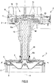
- Figure 1 shows a possible embodiment of a knitting machine according to the present invention, with some parts removed.
- the illustration of the machine is focalized on the bearing structure, on the needle cylinder, on the dial group and on the rotation translation means, so as to enable comprehension of the present invention.
- the basement of the knitting machine the section comprising the processing board, further components of the knitting head and the needle-bearing organ, the needles themselves and other parts of the knitting machine are not shown in detail in the figures, as of known type and conventional. From the point of view of knitting technology, the functioning of the entire knitting machine (for example the functioning of the knitting head, the cooperation between needles and threads etc.) is not described in detail, being known in the technical sector of the present invention.
- the knitting machine 1 comprises a bearing structure 2 and a needle cylinder C rotatably mounted to the bearing structure and rotatable selectively, by means of rotation means of the cylinder 7, about a rotation axis X of the needle cylinder.
- the rotation means of the cylinder 7 comprise, for example, an electric motor and an appropriate transmission (for example belt- or gear-driven) able to transmit the motion from the motor to the cylinder.
- the machine 1 further comprises a plurality of needles supported by the needle cylinder and mobile parallel to the rotation axis X so as to produce a knitted fabric.
- the needle cylinder can have a variable diameter according to knitting requirements; for example the diameter can be 4 inches, 8 inches, 16 inches, 24 inches.
- the needle cylinder can equivalently be a needle plate.
- the machine 1 further comprises a dial group 3, arranged superiorly of the needle cylinder C and comprising:
- the above plurality of devices comprises, for example, one or more hook command groups, a plurality of pliers groups, a plurality of cutters, a plurality of thread aspirating mouths, and possibly further auxiliary organs.
- the devices are not shown in the figures, as they can be of known type.
- the above-mentioned hooks are mobile organs, independently of one another, perpendicularly to the rotation axis of the needle cylinder and along a radial direction, in order to cooperate with the plurality of needles so as to produce a knitted fabric.
- the knitting machine 1 further comprises rotation transmission means 10, housed in the bearing structure 2 and interposed between the needle cylinder C and the dial group 3: the means 10 are configured for transmitting a rotation, generated by the rotation means of the cylinder 7, synchronously with the hook plate, in such a way that a determined rotation of the hook plate corresponds to a same rotation of the needle cylinder.
- the rotation transmission means comprise:
- the rotation transmission means 10 preferably further comprise:
- the lower belt connects the motor moving the needle cylinder with the relay shaft, while the upper belt connects the relay shaft with the pulley: the pulley then transfers the motion received to the flange (and from the flange to the hook plate) by interposing the engaging mechanism.
- the two belts (upper and lower) and the relay shaft in a lateral position enable carrying the rotation (produced by the rotation means of the cylinder) into the upper part of the machine, and from there to the dial group, overcoming the central object represented by the needle cylinder.
- This configuration of the rotation transmission means enables, in substance, arranging a pulley set in rotation constantly synchronously with the needle cylinder.
- the flange is always in connection with the shaft of the hook plate, and thus the rotation of the flange determines the rotary motion of the hook plate.
- the rotation transmission means comprise an engaging mechanism 20 interposed between the pulley 11 and the flange 13 and configured for operating selectively at least between an engaged position, in which it constrains the pulley and the flange to one another, determining a synchronous transmission of the rotary drive of the pulley to the flange and from the flange to the hook plate shaft, and a disengaged configuration, in which the flange 13 is free from constraints with respect to the pulley and the rotary motion of the pulley is not transmitted to the flange.
- the engaging mechanism 20 comprises at least an engaging organ 21 movable between the pulley and the flange, in a parallel direction to, or transversally or perpendicularly intersecting, the first rotation axis A of the pulley and the flange, between at least an engaged position and a disengaged position so as to determine passage of the engaged mechanism 20 respectively between the engaged position and the disengaged position.
- the engaging mechanism 20 further comprises actuating means 30, operatively active on the engaging organ 21 and configured for:
- angular engaging and disengaging positions 40 are preferably defined which are fewer than four or four and/or fewer than two or two and preferably (as in the embodiment of the figures) one and one only angular engaging and disengaging position 40 is defined.
- the engaging organ 21 is preferably movable, between the pulley 11 and the flange 13, in a substantially radial direction with respect to the first rotation axis A, i.e. substantially perpendicular to, and intersecting the, first rotation axis A of the pulley and the flange.
- the engaging organ 21 is preferably movable on a substantially horizontal plane.
- the first rotation axis A (of the pulley and the flange) preferably coincides with the rotation axis X of the needle cylinder C (and the hook plate); in this configuration (shown in the figures) the pulley and the flange are coaxial to one another and with the shaft of the hook plate, and are vertically aligned with the needle cylinder. This means that the needle cylinder, pulley, flange and hook plate can all rotate about the same rotation axis (A, X).
- the shaft 12 of the hook plate 5 preferably extends from an upper end 12a to a lower end 12b, the hook plate is preferably mounted at the lower end 12b of the shaft 12 of the hook plate shaft.
- the flange 13 is however preferably mounted coaxially to the upper end 12a of the hook plate shaft.
- the flange and the shaft of the hook plate can be made in a single piece, and in this case the flange emerges radially from the upper end of the hook plate shaft.
- the knitting machine 1 preferably comprises raising means 50 of the dial group 3, configured for vertically translating the whole dial group with respect to the needle cylinder along the rotation axis of the needle-bearing organ .
- the hook plate can be positioned at least between a lower (or lowered) position, in which it is neared to the needle-bearing organ, and an upper (or raised) position, in which it is vertically distanced from the needle-bearing organ (with respect to the lower position).
- the raising means 50 preferably comprise an actuator 51 active on the flange 13 and on the shaft of the hook plate. The vertical movement introduced by the raising means solidly involves the flange, the hook plate shaft and the hook plate.
- the relative rotation between the pulley and the flange, without transmission of drive, during the passage of the engaging mechanism from the disengaged position to the engaged position preferably has an angular dimension defining a resynchronising angle, the resynchronising angle being strictly smaller than 360°.
- the resynchronising angle is equal to the angle corresponding to the relative rotation between pulley and flange in order for the engaging organ 21 to reposition at the angular engaging and disengaging position 40.
- the engaging mechanism 20 preferably comprises the engaging organ 21, positioned on the pulley or flange, and at least an engaging/disengaging seating 25 defining the angular engaging and disengaging position 40 and positioned, respectively, on the flange or on the pulley.
- the engaging/disengaging seating 25 is configured for stably housing the engaging organ 21 when it is in the engaged position, enabling a synchronous transmission of the drive between the pulley and the flange, and consequently between the needle cylinder and the hook plate.
- the engaging organ 21 preferably comprises a wheel 22 rotatably mounted on a pin 23, the wheel being free to rotate about the pin and preferably being orientated on a plane comprising the first rotation axis A of the pulley and the flange.
- the pin 23 is preferably perpendicular to the wheel and is able to translate in a radial direction with respect to the first rotation axis A, such as to near or distance the wheel with respect to the first rotation axis.
- the translation of the pin 23 preferably determines the positioning of the wheel 22 at least between an advanced position, in which the wheel is radially neared to the first rotation axis A and the engaging organ is brought into the engaged position, and a retracted position, in which the wheel is radially distanced from the first rotation axis A and the engaging organ 21 is in the disengaged position.
- the actuating means 30 preferably comprise at least an elastic organ 31 active on the pin (and/or directly on the wheel) so as to exert thereon a thrust facing, in a radial direction, towards the first rotation axis; the thrust maintains the wheel 22 in an advanced position or pushes the wheel towards the advanced position.
- the actuating means preferably comprise a pair of elastic organs 31 active on the pin at two opposite sides of the pin with respect to the wheel 22.
- the elastic organ is preferably a spring or a helix spring 31.
- the engaging organ 21 is positioned on the pulley and the engaging/disengaging seating 25 is preferably positioned on the flange 13. Further, preferably, the whole engaging organ 21 is positioned externally of the flange, i.e. it is positioned at a radial distance from the first rotation axis A greater than the respective radial distance of the engaging/disengaging seating 25 from the first rotation axis.
- the engaging organ 21 is preferably positioned in such a way as to be at, and radially aligned with, the engaging/disengaging seating 25 when it reaches, by effect of the rotation of the pulley, the angular engaging and disengaging position 40.
- the engaging/disengaging seating 25 is preferably configured so as to enable automatic entry, via the actuating means 30, of the engaging organ 21 internally thereof, when the hook plate 5 is brought, by the raising means 50, into the lower position and the pulley has made a rotation equal to the resynchronizing angle.
- the flange 13 preferably exhibits an upper surface 14, a lower surface 15 and a lateral surface 16.
- the lateral surface 16 preferably has an annular shape and extends between, and connects, the upper surface and the lower surface.
- the engaging/disengaging seating 25 is preferably a radial recess 26 starting from the lateral surface 16 and externally open.
- the recess 26 (realizing the engaging/disengaging seating) is preferably also open at least at a portion of lower surface of the flange, so that -on the raising of the hook plate- the engaging organ is free to exit from the engaging/disengaging seating 25 and the engaging mechanism passes into the disengaged position.
- the upper surface 14 and the lower surface 15 are preferably orientated horizontally and at least an axial portion of the lateral surface (i.e. at least a portion of the thickness of the lateral surface) between the upper and lower surfaces and over the whole angular development of the flange, it is inclined transversally with respect to the upper and lower surfaces, so as to realize an annular thrust surface 18, not vertical, nearing the first rotation axis of the flange gradually as the lateral surface nears the lower surface.
- the annular thrust surface 18 is preferably configured to press on the engaging organ 21, i.e. on the wheel 22, when the hook plate 5 is brought by the raising means 50 in the lower position, so as to radially displace the engaging organ - when the engaging organ is dealigned from the angular engaging and disengaging position or positions - from the engaging position, radially neared to the first rotation axis, to the disengaged position, compressing the elastic organ (or elastic organs), so that the engaging organ, is positioned abuttingly externally on the lateral surface of the flange and the rotation of the pulley with respect to the flange determines a sliding of the engaging organ on the lateral surface of the flange without there occurring a transmission of drive from the pulley to the flange, and such that following a successive rotation of the pulley equal to the resynchronizing angle, the engaging organ reaches the engaging and disengaging seating and inserts therein radially by effect of the thrust exerted towards the first rotation axis by the
- the descent of the flange causes a retraction (towards the outside) of the wheel, caused by the annular thrust surface which presses on the wheel and compresses the springs, causing retraction of the pin on which the wheel is mounted; successively, the wheel remains pressed, by means of the thrust on the springs, against the lateral surface of the flange, and in this condition it drags on the lateral surface due to the rotation of the pulley.
- the rotation of the pulley brings the wheel into the angular engaging and disengaging position (i.e.
- the wheel when the pulley has rotated by the above-cited resynchronising angle), the wheel abuts the engaging/disengaging seating and enters it, here too by effect of the thrust of the springs.
- the entry brings the mechanism 20 into the engaged configuration: from there on the pulley and the flange are solidly constrained to one another, and the rotation of the pulley is transferred synchronously to the flange, and from there to the hook plate.
- the actuating means can comprise, in replacement or additionally to the elastic organ, an actuator (for example a piston or a linear motor) active on the engaging organ and a sensor.
- the sensor is active during the rotation of the pulley with the engaging organ in the disengaged position on the flange and is configured for detecting the presence of the engaging/disengaging seating: on reaching the seating, the sensor commands the activation of the actuator, which determines the entry of the engaging organ in the seating and the passage into the engaged position.
- the thrust surface 18 is preferably realised by a bevelling between the lateral surface 16 and the lower surface 15 of the flange 13.
- the thrust surface 18 is preferably defined as an inclined plane with respect to the vertical movement direction of the dial group between the lower position and the upper position.
- the engaging mechanism 20 preferably comprises a body 24 movably housing the engaging organ 21, in particular the pin 23 and/or the wheel 22, and the actuating means 30, in particular the elastic organ 31 (or the two springs 31 in the embodiment shown in the figures).
- the body 24 of the engaging mechanism 20 is preferably mounted solidly on the pulley and is therefore set in rotation by the pulley.
- the body 24 is preferably mounted on the pulley so as to be positioned externally with respect to the flange (on which the engaging/disengaging seating is present), in order to enable a radial movement of the engaging organ between the engaging and disengaging positions.
- the flange 13 preferably has a height, calculated as the axial distance between the upper surface 14 and the lower surface 15, greater than 5 mm and/or greater than 10 mm and/or greater than 20 mm and/or greater than 40 mm and/or greater than 60 mm.
- the height defines a height for raising the hook plate 5 at which the engaging mechanism is brought into the disengaging configuration and the motion of the needle cylinder is not transmitted to the hook plate.
- the raising means 50 of the dial group are preferably configured so as to position the hook plate in one or more intermediate positions, in each of which the hook plate is positioned at a respective intermediate vertical height between the height corresponding to the lower position and the height corresponding to the upper position. In each of the intermediate positions the engaging mechanism is in the engaged configuration and the hook plate is vertically partially distanced from the needle-bearing organ.
- the raising means of the dial group are preferably configured for vertically raising the hook plate even beyond the upper position; this happens following the disengagement of the hook plate and enables freeing up a greater space between the dial group and the needle cylinder useful for maintenance operations.
- the dial group proceeds with the vertical raising following the disengagement; in the further raising there are no contacts or interactions between the engaging organ (located on the pulley) and the overlying flange.
- a successive lowering of the dial group includes a first descent towards the upper position, at which the contact is re-established between the engaging organ and flange and starts the passage towards the engaged configuration (and towards the lower position of the dial group).
- the above-cited wheel 22 preferably has a cylindrical conformation and comprises a first flat lateral face 61, a second flat lateral face 62 and an annular surface 63 interposed between, and connecting, the lateral faces 61 and 62.
- the wheel 22 is preferably made of a metal material, for example iron or steel.
- the first wall 71 preferably lies on a plane that is parallel to the first rotation axis A and orientated substantially radially with respect to the first rotation axis A; the first wall 71 is configured for entering into contact with a portion of the first lateral face 61 of the wheel when the wheel enters the seating and is brought into the engaged position.
- the first wall 71 is preferably configured for receiving from the wheel 22, in particular from the first lateral face 61 of the wheel when the wheel is in the engaged position, a thrust determined by the rotation of the pulley, the thrust being transmitted to the first wall 71 of the seating and determining a synchronous and solidly constrained rotation of the flange with the pulley.
- the position of the first wall 71 in the flange is preferably more advanced than the position of the second wall 72 with respect to the rotation direction of the pulley and the flange.
- the second wall 72 preferably lies on a parallel plane to the first rotation axis A and inclined with respect to the plane on which the first wall lies, so that the distance between the first and the second wall, i.e. the width of the empty space between the first wall and the second wall, increases from the bottom surface 74 of the seating up to the lateral surface of the flange, at which the engaging/disengaging seating is open towards outside.
- the second wall 72 is preferably configured for entering into contact with a corner portion formed by the second lateral face 62 of the wheel 22 with the external annular surface 63 of the wheel, when the wheel enters into the seating and is brought into the engaged position.
- the second wall 72 is preferably inclined with respect to the first wall by an angle of greater than 1° and/or greater than 3° and/or greater than 5°.
- the width of the empty space between the first 71 and the second wall 72 of the seating 25 preferably increases linearly, starting from the bottom surface 74 towards the outside, according to the inclination of the second wall with respect to the first.
- the engaging/disengaging seating 25 provided with the second inclined wall 72 advantageously enables recuperating any play on entry of the wheel; in fact, the wheel enters the seating up to when the internal width of the seating corresponds to the width of the wheel. This guarantees the correct synchronising between the pulley and flange when the mechanism 20 is in the engaging configuration.
- the first wall 71 is advantageously flat since the first lateral face of the wheel abuts on the wall, which first lateral face constitutes the thrust face with which the wheel transmits the motion of the pulley to the seating, and from the seating to the whole flange.
- the rotation of the pulley 11 with respect to the flange 13 so as to follow the resynchronising angle, with the aim of bringing the wheel 22 to the engaging/disengaging seating preferably determines a translation of the wheel on the lateral surface 16 of the flange and in contact therewith; in this condition, the annular surface 63 of the wheel drags on the lateral surface of the flange and the wheel performs no rotation about the axis thereof.
- the raising of the hook plate into the upper position preferably determines the automatic exit of the wheel from the engaging/disengaging seating, which exit occurs by a rotation of the wheel with respect to the seating, preferably with respect at least to the second wall of the seating, in a first rotation direction.
- the exiting of the wheel from the seating determines the passage of the engaging mechanism into the disengaging configuration.
- the lowering of the hook plate into the lower position preferably determines the retraction of the wheel by effect of the thrust exerted by the annular thrust surface and the compression of the elastic organ, the retraction occurring contemporaneously with a rotation of the wheel on the annular thrust surface of the flange, according to a second rotation direction opposite the first rotation direction.
- the retraction predisposes the engaging mechanism for a successive passage, when the resynchronising has occurred between the pulley and the flange, into the engaged configuration.
- the seating can have the first wall and the second wall both not inclined and lying on a respective plane parallel to the first rotation axis A and orientated substantially radially with respect to the first rotation axis.
- the wheel preferably has the second lateral face thereof lying on a parallel plane to the first rotation axis A and inclined with respect to the plane on which the first lateral face lies, so that the distance between the first and the second lateral face increases from externally of the wheel towards the pin.
- the corner formed by the second wall of the seating with the external surface of the flange enters into contact with a portion of the second lateral face of the wheel, when the wheel enters the seating and is brought into the engaged position.
- the above-mentioned corner formed by the second wall of the seating with the external surface of the flange preferably can be bevelled or shaped so as to facilitate the entry of the wheel into the seating, enabling a partial entry of the wheel into the seating when the first lateral face of the wheel has gone beyond the second wall of the seating but has not yet reached the first wall of the seating (on which it abuts so as to transfer the rotary motion from the pulley to the flange).
- the rotation transmission means comprise at least a braking organ operatively active on the hook plate and configured for exerting a braking force on the hook plate when the pulley rotates, without any drive transmission, with respect to the flange and the wheel translates laterally, draggingly, on the lateral surface of the flange.
- the braking organ preferably exerts the braking force following a lowering of the plate into the lower position, for at least a 360° rotation of the pulley or for at least a rotation of the pulley by an angle equal to the resynchronising angle, such as to enable the engaging organ to reach the engaging/disengaging seating.
- the braking organ enables preventing, with the dial group in a lowered position and during the rotation of the pulley by the resynchronizing angle, the dragging of the wheel externally on the flange from causing an undesirable dragging of the hook plate.
- the braking organ is also configured to drag on the flange, so as to produce a friction thereof which keeps it stationary. In this way the friction of the braking organ compensates for the eventual thrust generated by the dragging of the wheel on the flange, guaranteeing that it is stationary during the resynchronising.
- the braking organ is an optional component.
- the braking organ can be a piston, for example pneumatic, commanded by a solenoid valve.
- the thrust organ is advantageously the above-mentioned wheel, but can also take on different conformations, for example with a pin, an inclined plane, etc.
- the rotation means 7 of the needle cylinder are preferably configured so as to set the needle cylinder - and therefore the drive pulley - in rotation in a single rotation direction, the rotation preferably being continuous regardless of the configuration assumed by the engaging mechanism.
- the bearing structure 2 preferably comprises a sleeve 80 arranged coaxially to the cylinder rotation axis X and provided with a through-opening crossed by and housing the above-mentioned shaft 12 of the hook plate.
- the sleeve is provided with a lower end to which the support plate 4 of the dial group is solidly mounted and from which the lower end of the shaft of the hook plate emerges inferiorly, to which lower end the hook plate is mounted.
- the sleeve structurally bears the support plate and the devices present thereon and enable the shaft of the hook plate to rotate and translate internally thereof, transmitting the rotation and vertical translation of the hook plate and the cutter.
- the sleeve 80 connects the plate 4 of the dial group to the bearing structure 2 and at the same time decouples the hook plate 5 from the plate 4, as it enables the shaft 12 - rotating internally thereof - to support and rotate the underlying hook plate. Further, the sleeve is moved vertically by the raising means 50, so that the whole dial group can be raised and lowered, but without this interfering with the rotation of the hook plate.
- the rotation transmission means comprise:
- the processing means are configured for comparing the first detecting datum with the second detecting datum, with the aim of verifying a determined condition of correspondence between the first reference angular position and the second reference angular position. This condition of correspondence is equivalent to a "synchronised configuration" of the hook plate with respect to the needle cylinder.
- the processing means are configured for controlling the synchronizing of the hook plate with respect to the needle cylinder when the engaging mechanism is in the engaged configuration and the motion generated by the rotation means of the cylinder is transmitted to the hook plate.
- the processing means are preferably configured so as to halt the knitting machine when the engaging mechanism is in the engaged configuration and the condition of correspondence is not satisfied.
- the correspondence condition preferably includes an angular lag, between the first reference angular position and the second reference angular position, that is nil or is a determined value.
- the first reference angular position is preferably one only for the whole rotation of the needle cylinder.
- the second reference angular position is preferably one only for the whole rotation of the hook plate.
- the first sensor and the second sensor are preferably proximity sensors of a magnetic or optical or capacitive or inductive or ultrasound type.
- the first sensor and/or the second sensor are preferably fixed.
- the first sensor is preferably configured for detecting the first angular reference position (relative to the needle cylinder), by detecting a determined position of the needle cylinder (for example a notch or pin on the cylinder or a determined reference needle) or the pulley.
- the second sensor is preferably configured for detecting the second angular reference position (relative to the hook plate), by detecting a position of the hook plate or the shaft of the hook plate or the flange or the cutter.
- the second sensor is preferably mounted on the support plate of the dial group; alternatively it can be positioned on the bearing structure, as long as it is able to detect the position of the hook plate or a correlated position of the hook plate, for example a position of the shaft of the hook plate or the flange or the cutter.
- the present invention is applicable on both new machines and already-existing machines, in the latter case for introducing an engaging mechanism according to the present invention, which enables selectively disengaging the rotation of the hook plate with respect to the rotation of the needle cylinder.
- the invention offers considerable advantages. Primarily, the whole invention enables obviating at least some of the drawbacks in the prior art.
- the present invention relates to a circular knitting machine characterised by an engaging/disengaging mechanism of the hook plate (and therefore of the cutter) with respect to the needle cylinder, which is of a different type with respect to the prior art.
- the described mechanism is of the continuously-synchronised type: this means that it is not necessary to wait for a determined angular position of the pulley with respect to the flange in order to carry out the disengaging of the hook plate (by vertical raising), nor is it necessary to return the pulley into a determined angular position in order to newly set up the rotation of the hook plate.
- the solution of the present invention enables disengaging in any angular position and autonomously returns the pulley into the correct position in which to reconnect the pulley to the flange, so that the pulley and flange return to rotate solidly and the synchronism is guaranteed (i.e. the angular velocity) in the rotation of the needle cylinder and the hook plate.
- the mechanism of the present invention enables guaranteeing a correct synchronising of the hook plate with respect to the needle cylinder: by synchronising is meant a condition in which each point of the hook plate, when the hook plate rotates, is always vertically aligned with a respective corresponding point of the underlying needle cylinder.
- the present description and the appended figures illustrate a preferred solution, in which the engaging organ is positioned on the pulley and the engaging/disengaging seating is located on the flange.
- the invention includes an equivalent variant embodiment in which the position of the elements is inverted, i.e. the engaging organ is positioned on the flange and the engaging/disengaging seating is located on the pulley.
- the lateral entry of the engaging organ in the seating enables maintaining the pulley/flange coupling, during the raising of the dial group by the raising means, up to a height equal to that of the flange, i.e. up to when the engaging organ exits inferiorly of the engaging/disengaging seating (in particular up to when the raising causes the exit of the engaging organ from the open recess on the lower surface of the flange).
- the lateral entry of the engaging organ in the seating enables maintaining the pulley/flange coupling stable for each raised height, up to a raising that is equal to the height (or axial thickness) of the flange.
- the wheel is laterally inserted in the recess that embodies the seating also during the raising of the flange, and this guarantees the coupling precision and the absence of bending or torsion stresses on the wheel.
- This is irrespective of the height of the lateral surface of the flange and therefore of the vertical height which it is necessary to reach in order to obtain the disengaging of the flange (and the halting of the transmission of the rotation from the pulley to the flange).
- the present solution enables reducing the wear of the mechanical organs involved in the disengaging and the engaging, in particular of the wheel and the seating.
- the radial motion of the engaging organ further enables realising a flange having a height (or width) that is selectable: the greater the height of the flange, the greater the vertical rise attained by the dial group at the moment of disengagement.
- the present invention describes engaging and disengaging means which do not suffer from the vertical distancing of the dial group from the underlying cylinder, and are able to operate in any condition with the same coupling precision and without being subjected to damaging stresses (for example bendings or torsions).
- the engaging organ of the present invention in particular in the wheel form thereof shown in the figures, efficiently enters the recess realising the seating, and is not working "projectingly" gradually as the dial group is being raised: on the contrary, it always maintains the same type of mechanical coupling, in particular between the lateral faces of the wheel and the walls of the engaging/disengaging seating, and produces a constant transmission of the rotary motion from the pulley to the flange.
- the greater vertical height reachable by the dial group at the moment of the disengagement constitutes a significant advantage in the sector, as it enables increasing the accessibility to the knitting head during maintenance.
- the present invention enables obtaining a disengagement height that is selectable and at least 10mm and/or at least 30mm and/or at least 60mm and/or at least 100mm.
- the present solution further enables defining a plurality of vertical positions, in a controlled way, that the dial group can assume.
- the actuator 51 of the raising means 50 can be a linear motor (or an electric rotary motor with a linear transmission of the motion) able to position the dial group at various intermediate heights between the lower position and the upper position (in which the disengaging occurs). This can be useful in certain knitting operations, in which slightly lifting the dial group with respect to the needle cylinder is desirable.
- a further advantage of the solution at the base of the present invention consists in disengaging and engaging the rotation of the hook plate (and the cutter while working, i.e. during the knitting operations).
- the hook group can be raised and then - after a revolution thereof -lowered, with the knitting machine in rotation: in this way a lag of 360° of the hook plate is obtained with respect to the cylinder.
- the engaging mechanism of the present invention further enables, in the embodiment thereof including an active activation of the engaging organ (in place of the elastic organs), maintaining the dial group in a disengaged configuration for a desired number of rotations of the cylinder, then to proceed to automatic resynchronising and re-engaging.
- the present invention enables simplifying the machine maintenance operations, and in general improving the accessibility to the dial group and the knitting head. Further, the present invention enables arranging the disengaging means of the hook plate (and the cutter) able to guarantee a correct, precise and repeatable synchronisation of the hook plate with respect to the needle cylinder. Further, the present invention enables having disengaging means of the hook plate (and the cutter) that are characterised by a high degree of reliability, resistance to wear and stress and long working life.
- the knitting machine of the present invention is characterised by a competitive cost and a simple and rational structure.
Landscapes
- Engineering & Computer Science (AREA)
- Textile Engineering (AREA)
- Knitting Machines (AREA)
- Yarns And Mechanical Finishing Of Yarns Or Ropes (AREA)
- Treatment Of Fiber Materials (AREA)
Claims (15)
- Machine de tricotage circulaire (1) pour vêtement tricoté ou article chaussants, comprenant :- une structure de support (2) ;- au moins un organe de support d'aiguilles ou un cylindre d'aiguilles (C) monté de manière à pouvoir tourner dans la structure de support et pouvant tourner sélectivement, à l'aide de moyen de rotation du cylindre (7), autour d'un axe de rotation (X) du cylindre de support d'aiguilles ;- une pluralité d'aiguilles supportées par le cylindre d'aiguilles et mobiles par rapport à un axe de rotation (X) du cylindre d'aiguilles afin de produire un textile tricoté ;- un groupe cadran (3) disposé au-dessus du cylindre d'aiguilles et comprenant :- un anneau de support (4) contraint solidement à la structure de support et coaxial par rapport au cylindre d'aiguilles ;- un organe de support de crochets, ou une plaque de crochets (5), portant une pluralité de crochets, la plaque de crochets étant montée de manière à pouvoir tourner à la plaque de support (4) d'une manière telle qu'elle tourne autour d'un axe de rotation respectif coïncidant avec l'axe de rotation (X) du cylindre d'aiguilles ;- un organe de transport et de coupe de fil, ou cutter (6), monté externellement à la plaque de support (4) et contraint solidement à la plaque de crochets (5), d'une manière telle à pouvoir tourner ensemble avec la plaque ;la machine de tricotage comprenant en outre un moyen de transmission de rotation (10), logé dans la structure de support et fonctionnellement interposé entre le cylindre d'aiguilles (C) et le groupe cadran (3), configuré pour transmettre une rotation, générée par ledit moyen de rotation du cylindre, de manière synchrone par rapport à la plaque de crochets (5), de sorte qu'une rotation déterminée de la plaque de crochets correspond à une même rotation du cylindre d'aiguilles,
le moyen de transmission de rotation (10) comprenant :- une poulie d'entraînement (11) recevant un mouvement de rotation du moyen de rotation de cylindre (7) et tournant, de manière synchrone par rapport au cylindre d'aiguilles (C), autour d'un premier axe de rotation (A) ;- un arbre de plaque de crochets (12), coaxialement monté à la plaque de crochets (5) et configuré afin de transmettre une rotation à la plaque de crochets ;- une collerette (13), configurée afin de transmettre un mouvement de rotation à l'arbre (12) de la plaque de crochets, fonctionnellement interposée entre la poulie (11) et l'arbre de crochets et positionnée au niveau de la poulie, la collerette (13) étant capable de tourner autour du premier axe de rotation (A) ;la machine de tricotage étant caractérisée en ce que le moyen de transmission de rotation (10) comprend un mécanisme d'engagement (20) fonctionnellement interposé entre la poulie (11) et la collerette (13) et configuré pour fonctionner sélectivement au moins entre une configuration engagée, dans laquelle il contraint la poulie et la collerette l'une par rapport à l'autre, déterminant une transmission synchrone de l'entraînement rotatif de la poulie à la collerette et depuis la collerette à l'arbre de plaque de crochets, et une configuration désengagée, dans laquelle la collerette est libre de contraintes par rapport à la poulie et le mouvement de rotation de la poulie n'est pas transmis à la collerette,
où le mécanisme d'engagement (20) comprend au moins un organe d'engagement (21) mobile, entre la poulie (11) et la collerette (13), dans un sens qui est parallèle à, ou transversalement ou perpendiculairement en intersection, au premier axe de rotation (A) de la poulie et de la collerette, entre au moins une position engagée et une position désengagée afin de déterminer le passage du mécanisme engagé (20) respectivement entre la position engagée et la position désengagée,
et le mécanisme d'engagement (20) comprenant un moyen d'actionnement (30) fonctionnellement actif sur l'organe d'engagement (21) et configuré pour permettre le passage du mécanisme d'engagement (20) depuis la configuration engagée vers la configuration désengagée dans n'importe quelle position angulaire prise par la collerette (13) ou la poulie (11), et pour déterminer le passage du mécanisme d'engagement depuis la configuration désengagée vers la configuration engagée exclusivement avec l'organe d'engagement (21) positionné à un nombre prédéterminé et limité de positions angulaires d'engagement et de désengagement (40) définies sur la collerette (13) ou la poulie (11). - Machine de tricotage circulaire (1) selon la revendication 1, dans laquelle, sur la collerette (13) ou la poulie (11), un nombre de positions angulaires d'engagement et de désengagement (40) sont définies qui sont inférieures à quatre ou de quatre ou inférieures à deux ou de deux ou,
sur la collerette ou la poulie, une et uniquement une position angulaire d'engagement et de désengagement (40) étant définie. - Machine de tricotage circulaire (1) selon la revendication 1 ou 2, l'organe d'engagement (21) étant mobile, entre la poulie (11) et la collerette (13), dans un sens sensiblement radial par rapport au premier axe de rotation (A), c'est-à-dire sensiblement perpendiculaire à et en intersection avec le premier axe de rotation de la poulie et de la collerette, ou
le mécanisme d'engagement (20) comprenant l'organe d'engagement (21), positionné sur la poulie (11) ou sur la collerette (13), et au moins une assise d'engagement/de désengagement (25) définissant la position angulaire d'engagement et de désengagement (40) et positionnée, respectivement, sur la collerette (13) ou sur la poulie (11), l'assise d'engagement/de désengagement (25) étant configurée afin de loger stablement l'organe d'engagement (21) lorsque dans la position engagée, permettant une transmission synchrone de l'entraînement entre la poulie (11) et la collerette (13), et par conséquent entre le cylindre d'aiguilles (C) et la plaque de crochets (5). - Machine de tricotage circulaire (1) selon l'une quelconque des revendications précédentes, la poulie (11) tournant autour d'un axe de rotation coïncidant avec l'axe de rotation (X) du cylindre d'aiguilles, et/ou l'arbre (12) de la plaque de crochets s'étendant depuis une extrémité supérieure (12a) vers une extrémité inférieure (12b), la plaque de crochets (5) étant montée au niveau de l'extrémité inférieure (12b) de l'arbre (12) de la plaque de crochets, ou la collerette (13) étant montée coaxialement à l'extrémité supérieure (12a) de l'arbre de plaque de crochets, et/ou le premier axe de rotation (A) coïncidant avec l'axe de rotation (X) du cylindre d'aiguilles (C) et de la plaque de crochets (5).
- Machine de tricotage circulaire (1) selon l'une quelconque des revendications précédentes, comprenant un moyen d'élévation (50) du groupe cadran (3), configuré pour assurer la translation verticalement du groupe cadran complet (3) par rapport au cylindre d'aiguilles (C) le long de l'axe de rotation (X) du cylindre d'aiguilles, afin de positionner la plaque de crochets (5) au moins entre une position inférieure, dans laquelle elle est plus proche de la plaque d'aiguilles, et une position supérieure, dans laquelle elle est verticalement éloignée du cylindre d'aiguilles par rapport à la position inférieure, le moyen d'élévation (50) comprenant un dispositif d'actionnement (51) actif sur la collerette (13) et/ou sur l'arbre (12) de la plaque de crochets (5), et/ou un passage de la plaque de crochets (5), par le moyen d'élévation (50) du groupe cadran, depuis la position inférieure vers la position supérieure, déterminant automatiquement le passage du mécanisme d'engagement (20) dans la position désengagée, l'élimination de la contrainte de la collerette (13) par rapport à la poulie (11), déterminant l'arrêt de la plaque de crochets (5) et le maintien de la poulie (11) en rotation.
- Machine de tricotage circulaire (1) selon la revendication précédente, un passage de la plaque de crochets (5) par le moyen d'élévation (50) du groupe cadran depuis la position supérieure vers la position inférieure et une rotation relative, sans transmission de l'entraînement, entre la poulie (11) et la collerette (13) jusqu'à l'atteinte, par l'organe d'engagement (21), de la position angulaire d'engagement et de désengagement (40), déterminent un passage automatique du mécanisme d'engagement (20) dans la position engagée, contraignant la collerette (13) par rapport à la poulie (11) et déterminant la rotation synchrone de la plaque de crochets (5) par rapport au cylindre d'aiguilles (C), et/ou la rotation relative entre la poulie (11) et la collerette (13), sans la transmission d'entraînement, durant le passage du mécanisme d'engagement (20) depuis la position désengagée vers la position engagée, ayant une dimension angulaire définissant un angle de resynchronisation, l'angle de resynchronisation étant strictement inférieur à 360°C.
- Machine de tricotage circulaire (1) selon l'une quelconque des revendications précédentes, l'organe d'engagement (21) comprenant une roue (22) montée de manière à pouvoir tourner sur une broche (23), la roue (22) étant libre de tourner autour de la broche (23) et étant orientée sur un plan comprenant le premier axe de rotation (A) de la poulie et de la collerette, la broche (23) étant perpendiculaire à la roue et étant capable d'effectuer une translation dans un sens radial par rapport au premier axe de rotation (A), afin de rapprocher ou d'écarter la roue par rapport au premier axe de rotation (A), et/ou la translation de la broche (23) déterminant le positionnement de la roue (22) au moins entre une position avancée, dans laquelle la roue est radialement rapprochée du premier axe de rotation (A) et l'organe d'engagement étant porté dans la position engagée, et une position rétractée, dans laquelle la roue (22) est radialement écartée du premier axe de rotation et l'organe d'engagement (21) se trouve dans la position désengagée, et/ou le moyen d'actionnement (30) comprend au moins un organe élastique (31) actif sur la broche (23) ou sur la roue (22) afin d'exercer dessus une poussée faisant face, dans un sens radial, vers le premier axe de rotation (A), afin de maintenir la roue (22) dans une position avancée ou de pousser la roue (22) vers la position avancée, ledit organe élastique étant préférablement un ressort ou un ressort en hélice (31).
- Machine de tricotage circulaire (1) selon l'une quelconque des revendications précédentes, l'organe d'engagement (21) étant positionné sur la poulie (11) et l'assise d'engagement/de désengagement (25) étant positionnée sur la collerette (13) et/ou l'organe d'engagement (21) étant positionné externellement à la collerette c'est-à-dire qu'il est positionné à une distance radiale depuis le premier axe de rotation (A) supérieure à la distance radiale respective de l'assise d'engagement/de désengagement (25) depuis le premier axe de rotation (A).
- Machine de tricotage circulaire (1) selon l'une quelconque des revendications précédentes, l'organe d'engagement (21) étant positionné d'une manière à se trouver au niveau et radialement aligné sur l'assise d'engagement/de désengagement (25) lorsqu'il atteint, par l'effet de la rotation de la poulie (11), la position angulaire d'engagement et de désengagement (40), et/ou l'assise d'engagement/de désengagement (25) étant configurée afin de permettre l'entrée automatique, par l'intermédiaire du moyen d'actionnement (30), de l'organe d'engagement (21) au plan interne de celui-ci, lorsque la plaque de crochets (5) est portée, par le moyen d'élévation (50), dans la position inférieure et que la poulie (11) a effectué une rotation égale à l'angle de resynchronisation.
- Machine de tricotage circulaire (1) selon l'une quelconque des revendications précédentes, la collerette (13) faisant preuve d'une surface supérieure (14), d'une surface inférieure (15) et d'une surface latérale (16) de forme annulaire, s'étendant entre, et reliant, la surface supérieure et la surface inférieure, l'assise d'engagement/de désengagement (25) étant un renfoncement radial (26) commençant depuis la surface latérale (16) et ouvert externellement, et/ou le renfoncement (26) réalisant l'assise d'engagement/de désengagement (25) est ouvert au moins au niveau d'une portion de la partie de la surface inférieure (15) de la collerette, de sorte que l'élévation de la plaque de crochets (5) dans la position supérieure détermine la sortie de l'organe d'engagement (21) depuis l'assise d'engagement/de désengagement (25) et le passage du mécanisme d'engagement (20) dans la configuration désengagée.
- Machine de tricotage circulaire (1) selon la revendication précédente, lorsqu'elle dépend de la revendication 7, la surface supérieure (14) et la surface inférieure (15) étant orientées horizontalement et au moins une partie axiale de la surface latérale (16), entre la surface supérieure et inférieure et sur le développement angulaire complet de la collerette (13), et inclinée transversalement par rapport à la surface supérieure et inférieure, afin de réaliser une surface de poussée annulaire (18) rapprochant le premier axe de rotation de la collerette progressivement lorsque la surface latérale (16) approche la surface inférieure (15), et/ou la surface de poussée annulaire (18) est configurée pour presser sur l'organe d'engagement (21), en particulier la roue (22), lorsque la plaque de crochets (5) est portée par le moyen d'élévation (50) dans la position inférieure, afin de déplacer radialement l'organe d'engagement - lorsque l'organe d'engagement est désaligné de la position ou des positions angulaire-s d'engagement et de désengagement - depuis la position d'engagement, radialement rapproché du premier axe de rotation, vers la position de libération, comprimant ledit organe élastique (31), de sorte que l'organe d'engagement (21), en particulier la roue, est positionné en butée externellement de la surface latérale (16) de la collerette (13) et la rotation de la poulie (11) par rapport à la collerette détermine un coulissement de l'organe d'engagement (21), préférablement de la roue (22), sur la surface latérale de la collerette sans qu'apparaisse une transmission d'entraînement de la poulie vers la collerette, et de sorte que suite à une rotation successive de la poulie de l'angle de resynchronisation, l'organe d'engagement atteint l'assise d'engagement et de désengagement (25) et s'insère à l'intérieur radialement par l'effet de la poussée exercée vers le premier axe de rotation (A) par ledit organe élastique (31).
- Machine de tricotage circulaire (1) selon l'une quelconque des revendications précédentes, la collerette (13) ayant une hauteur, calculée comme distance axiale entre la surface supérieure (14) et la surface inférieure (15), supérieure à 10 mm ou supérieure à 20 mm ou supérieure à 40 mm ou supérieure à 60 mm, la hauteur définissant une hauteur d'élévation de la plaque de crochets (5) à laquelle le mécanisme d'engagement est porté en configuration désengagée et le mouvement du cylindre d'aiguilles n'est pas transmis à la plaque de crochets (5), et/ou le moyen d'élévation (50) du groupe cadran (3) est configuré pour le positionnement de la plaque de crochets (5) dans une ou plusieurs des positions intermédiaires, dans chacune desquelles la plaque de crochets est positionnée à une hauteur verticale intermédiaire respective entre la hauteur correspondant à la position inférieure et la hauteur correspondant à la position supérieure, dans laquelle dans chacune des positions intermédiaires le mécanisme d'engagement se trouve dans la configuration engagée et la plaque de crochets est verticalement partiellement écartée du cylindre d'aiguilles.
- Machine de tricotage circulaire (1) selon l'une quelconque des revendications précédentes, dans laquelle la roue (22) présente une conformation cylindrique et comprend une première (61) et une seconde face latérale (62) qui est plate et une surface annulaire (63) interposée entre, et reliant, les faces latérales, et/ou l'assise d'engagement/de désengagement (25), réalisées comme renfoncement vertical (26) dans la surface latérale (16) de la collerette (13), s'étend de manière angulaire entre une première paroi (71) et une seconde paroi (72), entre lesquelles un espace vide est présent (73), destiné à loger l'organe d'engagement (21) lorsqu'il est porté dans la position engagée, l'assise (25) se terminant au plan interne de la collerette avec une surface inférieure (74), et/ou la première paroi (71) reposant sur un plan qui est parallèle au premier axe de rotation (A) et orientée sensiblement radialement par rapport au premier axe de rotation, la première paroi étant configurée afin d'entrer en contact avec une portion de la première face latérale (61) de la roue (22) lorsque la roue entre dans l'assise et est portée en position engagée.
- Machine de tricotage circulaire (1) selon la revendication précédente, dans laquelle la première paroi (71) est configurée afin de recevoir depuis la roue, en particulier depuis la première face latérale (61) de la roue, lorsque la roue se trouve en position engagée, une poussée déterminée par la rotation de la poulie (11), la poussée étant transmise à la première paroi (71) de l'assise (25) et déterminant une rotation synchrone et solide de la collerette (13) avec la poulie (11), et/ou la seconde paroi (72) reposant sur un plan qui est parallèle au premier axe de rotation (A) et incliné par rapport au plan sur lequel la première paroi repose, de sorte que la distance entre la première (71) et la seconde paroi (72), c'est-à-dire la largeur de l'espace vide (73) entre la première paroi et la seconde paroi, augmente depuis la surface inférieure (74) de l'assise (25) jusqu'à la surface latérale (16) de la collerette, au niveau de laquelle l'assise d'engagement/de désengagement (25) est ouverte vers l'extérieur, et/ou la seconde paroi (72) étant configurée pour entrer en contact avec une partie de coin formée par la seconde face latérale (62) de la roue avec la surface annulaire externe (63) de la roue (22), lorsque la roue (22) entre dans l'assise (25) et est portée en position engagée.
- Machine de tricotage circulaire (1) selon l'une quelconque des revendications précédentes, le moyen de transmission (10) de la rotation comprenant :- un moyen de traitement ;- un premier capteur positionné sur la structure de support (2) et configuré afin de détecter une première position angulaire de référence par rapport au cylindre d'aiguilles (C), durant la rotation du cylindre d'aiguilles, et afin de transmettre au premier moyen de traitement une première date de détection de la première position angulaire de référence ;- un second capteur positionné sur le groupe cadran (3) et configuré pour détecter une seconde position angulaire de référence par rapport à la plaque de crochets (5), ou directement corrélé à la plaque de crochets (5), durant la rotation de la plaque de crochets (5), et pour transmettre au moyen de traitement une seconde date de détection de la seconde position angulaire de référence ;le moyen de traitement étant configuré et prédisposé pour comparer la première date de détection à la seconde date de détection, dans le but de vérifier un état déterminé de correspondance entre la première position angulaire de référence et la seconde position angulaire de référence, la condition de correspondance étant équivalente à une configuration synchronisée de la plaque de crochets (5) par rapport au cylindre d'aiguilles (C), et le moyen de traitement étant configuré et prédisposé pour commander la synchronisation de la plaque de crochets (5) par rapport au cylindre d'aiguilles (C) lorsque le mécanisme d'engagement (20) se trouve dans la configuration engagée et que le mouvement généré par le moyen de rotation (7) du cylindre est transmis à la plaque de crochets (5), et/ou le moyen de traitement est configuré afin de stopper la machine de tricotage (1) lorsque le mécanisme d'engagement (20) se trouve dans la configuration engagée et que l'état de correspondance n'est pas vérifié, ou l'état de correspondance comprend un décalage angulaire, entre la première position angulaire de référence et la seconde position angulaire de référence, qui est nul ou qui est une valeur déterminée, et/ou le premier capteur et le second capteur étant des capteurs de proximité.
Applications Claiming Priority (2)
| Application Number | Priority Date | Filing Date | Title |
|---|---|---|---|
| IT000150A ITBS20130150A1 (it) | 2013-10-24 | 2013-10-24 | Macchina tessile circolare con meccanismo di innesto e sgancio del platorello del gruppo platò |
| PCT/IB2014/064956 WO2015059592A1 (fr) | 2013-10-24 | 2014-09-30 | Métier à tricoter circulaire à mécanisme de mise en prise et de libération de prise de la plaque à crochets du groupe plateau |
Publications (2)
| Publication Number | Publication Date |
|---|---|
| EP3060708A1 EP3060708A1 (fr) | 2016-08-31 |
| EP3060708B1 true EP3060708B1 (fr) | 2019-03-13 |
Family
ID=49841708
Family Applications (1)
| Application Number | Title | Priority Date | Filing Date |
|---|---|---|---|
| EP14789411.7A Active EP3060708B1 (fr) | 2013-10-24 | 2014-09-30 | Métier à tricoter circulaire à mécanisme de mise en prise et de libération de prise de la plaque à crochets du groupe plateau |
Country Status (9)
| Country | Link |
|---|---|
| US (1) | US10240266B2 (fr) |
| EP (1) | EP3060708B1 (fr) |
| KR (1) | KR102215195B1 (fr) |
| CN (1) | CN104562409B (fr) |
| BR (1) | BR112016008514B1 (fr) |
| IT (1) | ITBS20130150A1 (fr) |
| TR (1) | TR201908552T4 (fr) |
| TW (1) | TWI592533B (fr) |
| WO (1) | WO2015059592A1 (fr) |
Families Citing this family (14)
| Publication number | Priority date | Publication date | Assignee | Title |
|---|---|---|---|---|
| IT201600072994A1 (it) | 2016-07-13 | 2018-01-13 | Lonati Spa | Dispositivo prelevatore per operare il prelievo di un manufatto tubolare a maglia da una macchina circolare per maglieria, calzetteria o simile e il suo trasferimento ad un’unita’ atta ad eseguire ulteriori operazioni sul manufatto. |
| KR101944682B1 (ko) * | 2017-06-15 | 2019-01-31 | 박정환 | 파일 조직 발가락 양말 제조장치 |
| USD893554S1 (en) * | 2017-11-23 | 2020-08-18 | Santoni S.P.A. | Textile machine |
| CN107805876A (zh) * | 2017-11-24 | 2018-03-16 | 新昌县振兴纺织机械有限公司 | 一种用于织袜缝头一体机的定位顶出装置 |
| CN107938143A (zh) * | 2017-12-05 | 2018-04-20 | 杭州高腾机电科技有限公司 | 针织圆机针盘升降装置 |
| TWI687563B (zh) * | 2018-05-23 | 2020-03-11 | 昊佑精機工業有限公司 | 圓織機改良結構 |
| TWD207731S (zh) * | 2019-06-12 | 2020-10-11 | 義大利商聖東尼股份公司 | 紡織機組件 |
| TWD208194S (zh) * | 2019-06-12 | 2020-11-11 | 義大利商聖東尼股份公司 | 紡織機組件 |
| IT201900009216A1 (it) * | 2019-06-17 | 2020-12-17 | Santoni & C Spa | Macchina tessile circolare con sistema di sfasamento della camma maglia del piatto degli aghi |
| TWD208198S (zh) * | 2019-06-18 | 2020-11-11 | 義大利商聖東尼股份公司 | 紡織機構件 |
| TWD210323S (zh) * | 2019-06-18 | 2021-03-11 | 義大利商聖東尼股份公司 | 紡織機構件 |
| TWD210322S (zh) * | 2019-06-18 | 2021-03-11 | 義大利商聖東尼股份公司 | 紡織機構件 |
| TWD207736S (zh) * | 2019-06-18 | 2020-10-11 | 義大利商聖東尼股份公司 | 紡織機構件 |
| IT201900009495A1 (it) * | 2019-06-19 | 2020-12-19 | Santoni & C Spa | Macchina tessile circolare con sistema di sfasamento del piatto degli aghi rispetto al cilindro degli aghi |
Family Cites Families (12)
| Publication number | Priority date | Publication date | Assignee | Title |
|---|---|---|---|---|
| IT992223B (it) * | 1973-08-07 | 1975-09-10 | Billi Spa | Congegno di trasmissione del moto al disco o platorello degli uncini con innesto di sfasamento del plato rello |
| US4580418A (en) * | 1978-08-17 | 1986-04-08 | Yang Ping Chin | Oscillation damping and counterpoising circular knitting machine |
| IT1121179B (it) * | 1979-07-09 | 1986-03-26 | Micheletti Arrigo | Macchina circolare per calze e simili con tamburo delle camme e tamburo programmatore montati coassialmente al cilindro degli aghi |
| US4339932A (en) * | 1979-10-09 | 1982-07-20 | Francesco Lonati | Machine for knitting a tubular fabric |
| US4711100A (en) * | 1982-07-14 | 1987-12-08 | Tibbals Jr E C | Circular weft knitting machine |
| US4608839A (en) * | 1982-07-14 | 1986-09-02 | Tibbals Jr Edward C | Circular weft knitting machines |
| IT1274916B (it) * | 1994-09-27 | 1997-07-25 | Matec Srl | Gruppo di trasmissione del moto al tubo di aspirazione della calza in macchina circolare per calzetteria. |
| ITBS20050007A1 (it) * | 2005-01-28 | 2006-07-29 | Sangiacomo Spa | Dispositivo di comando del platorello in macchine circolari per calzetteria, maglieria e simile |
| ITMI20080397A1 (it) * | 2008-03-10 | 2009-09-11 | Lonati Spa | Procedimento ed apparecchiatura per eseguire la chiusura di un manufatto tubolare a maglia in corrispondenza di una sua estremita' assiale, al termine del suo ciclo di produzione su una macchina circolare per maglieria, calzetteria o simile. |
| ITMI20080398A1 (it) * | 2008-03-10 | 2009-09-11 | Lonati Spa | Dispositivo prelevatore per operare il prelievo di un manufatto tubolare a maglia da una macchina circolare per maglieria, calzetteria o simile e il suo trasferimento ad un'unita' atta ad eseguire ulteriori operazioni sul manufatto. |
| ITMI20110620A1 (it) * | 2011-04-13 | 2012-10-14 | Santoni & C Spa | Macchina circolare per maglieria o per calzetteria con accessibilita' alla testa tessile migliorata. |
| CN203174296U (zh) * | 2013-03-22 | 2013-09-04 | 浙江叶晓针织机械有限公司 | 一种织袜机 |
-
2013
- 2013-10-24 IT IT000150A patent/ITBS20130150A1/it unknown
-
2014
- 2014-03-24 CN CN201410112077.8A patent/CN104562409B/zh active Active
- 2014-09-30 TR TR2019/08552T patent/TR201908552T4/tr unknown
- 2014-09-30 WO PCT/IB2014/064956 patent/WO2015059592A1/fr not_active Ceased
- 2014-09-30 US US15/028,339 patent/US10240266B2/en active Active
- 2014-09-30 EP EP14789411.7A patent/EP3060708B1/fr active Active
- 2014-09-30 KR KR1020167013534A patent/KR102215195B1/ko active Active
- 2014-09-30 BR BR112016008514-0A patent/BR112016008514B1/pt active IP Right Grant
- 2014-10-23 TW TW103136614A patent/TWI592533B/zh active
Non-Patent Citations (1)
| Title |
|---|
| None * |
Also Published As
| Publication number | Publication date |
|---|---|
| BR112016008514B1 (pt) | 2021-11-23 |
| TWI592533B (zh) | 2017-07-21 |
| TW201520392A (zh) | 2015-06-01 |
| CN104562409A (zh) | 2015-04-29 |
| WO2015059592A1 (fr) | 2015-04-30 |
| KR20160075650A (ko) | 2016-06-29 |
| BR112016008514A2 (pt) | 2017-08-01 |
| CN104562409B (zh) | 2017-04-12 |
| EP3060708A1 (fr) | 2016-08-31 |
| KR102215195B1 (ko) | 2021-02-15 |
| ITBS20130150A1 (it) | 2015-04-25 |
| US20160258087A1 (en) | 2016-09-08 |
| US10240266B2 (en) | 2019-03-26 |
| TR201908552T4 (tr) | 2019-07-22 |
Similar Documents
| Publication | Publication Date | Title |
|---|---|---|
| EP3060708B1 (fr) | Métier à tricoter circulaire à mécanisme de mise en prise et de libération de prise de la plaque à crochets du groupe plateau | |
| JP5389831B2 (ja) | 靴下類等のための円形編機から筒状ニット製品を取り出し、取り出された製品を、該製品に更なる作業を行うべく適合されたユニットに移すためのピックアップ装置 | |
| KR20100127221A (ko) | 특히 관형 편물의 축방향 단부에서 관형 편물의 자동화된 폐쇄를 위한 봉제 또는 루핑 스테이션을 위한 관형 편물용 회전 디바이스 | |
| KR102544766B1 (ko) | 원형 편직기 및 원형 편직기의 바늘을 이동시키기 위한 방법 | |
| WO2011042299A1 (fr) | Métier à tricoter circulaire permettant la fabrication d'articles d'habillement du type sans couture à fonctionnalité accrue | |
| KR102477441B1 (ko) | 싱커 구동 장치를 구비한 편물, 양말류 등을 위한 원형 기계 | |
| KR20180090781A (ko) | 원형 편물기로부터 관형상 편성 물품을 픽업하는 장치 및 방법 | |
| CN1742125B (zh) | 带有驱动脱圈沉降片装置的用于袜类等的圆形针织机 | |
| US20100224113A1 (en) | Servo Driven Crank Adjusted Shifting Mechanism | |
| KR20100115713A (ko) | 재봉기 | |
| WO2009033846A1 (fr) | Remmailleuse droite pour des objets tricotés, à utilisation hautement polyvalente | |
| JPH03220347A (ja) | 丸編み機 | |
| CN101613908B (zh) | 结构非常简单的带有纱线切割装置的单针筒圆型针织机 | |
| CN101063250B (zh) | 用于改进线型经编针织机的导纱器穿纱的装置 | |
| CN100422417C (zh) | 针织机用的给纱机构 | |
| KR101576837B1 (ko) | 가동싱커를 구비하는 횡편기 | |
| EP3395736B1 (fr) | Dispositif d'alimentation de rouleaux | |
| EP0311207A2 (fr) | Dispositif d'alimentation de fil pour des fils à caractère élastique pour un métier à tricoter circulaire notamment pour un métier à tricoter des bas | |
| CN114080476B (zh) | 具有用于针板的成圈三角的偏置系统的圆形针织机 | |
| JP4390748B2 (ja) | 丸編み機を用いた編成方法及び丸編み機 | |
| EP1716996B1 (fr) | Machine pour la fabrication de joues de bobines de cables électriques par clouage de pièces en bois | |
| RU2028202C1 (ru) | Отрезное устройство автомата для правки и резки проволоки | |
| CN113512808A (zh) | 一种圆形针织机的线圈松紧度调节装置 | |
| RU2455405C2 (ru) | Устройство и способ для выравнивания края, окружающего конец кругловязаного изделия |
Legal Events
| Date | Code | Title | Description |
|---|---|---|---|
| PUAI | Public reference made under article 153(3) epc to a published international application that has entered the european phase |
Free format text: ORIGINAL CODE: 0009012 |
|
| 17P | Request for examination filed |
Effective date: 20160321 |
|
| AK | Designated contracting states |
Kind code of ref document: A1 Designated state(s): AL AT BE BG CH CY CZ DE DK EE ES FI FR GB GR HR HU IE IS IT LI LT LU LV MC MK MT NL NO PL PT RO RS SE SI SK SM TR |
|
| AX | Request for extension of the european patent |
Extension state: BA ME |
|
| GRAP | Despatch of communication of intention to grant a patent |
Free format text: ORIGINAL CODE: EPIDOSNIGR1 |
|
| STAA | Information on the status of an ep patent application or granted ep patent |
Free format text: STATUS: GRANT OF PATENT IS INTENDED |
|
| INTG | Intention to grant announced |
Effective date: 20181012 |
|
| GRAS | Grant fee paid |
Free format text: ORIGINAL CODE: EPIDOSNIGR3 |
|
| GRAA | (expected) grant |
Free format text: ORIGINAL CODE: 0009210 |
|
| STAA | Information on the status of an ep patent application or granted ep patent |
Free format text: STATUS: THE PATENT HAS BEEN GRANTED |
|
| AK | Designated contracting states |
Kind code of ref document: B1 Designated state(s): AL AT BE BG CH CY CZ DE DK EE ES FI FR GB GR HR HU IE IS IT LI LT LU LV MC MK MT NL NO PL PT RO RS SE SI SK SM TR |
|
| AX | Request for extension of the european patent |
Extension state: BA ME |
|
| REG | Reference to a national code |
Ref country code: GB Ref legal event code: FG4D |
|
| REG | Reference to a national code |
Ref country code: CH Ref legal event code: EP Ref country code: AT Ref legal event code: REF Ref document number: 1107782 Country of ref document: AT Kind code of ref document: T Effective date: 20190315 |
|
| REG | Reference to a national code |
Ref country code: IE Ref legal event code: FG4D |
|
| REG | Reference to a national code |
Ref country code: DE Ref legal event code: R096 Ref document number: 602014042900 Country of ref document: DE |
|
| REG | Reference to a national code |
Ref country code: NL Ref legal event code: MP Effective date: 20190313 |
|
| REG | Reference to a national code |
Ref country code: LT Ref legal event code: MG4D |
|
| PG25 | Lapsed in a contracting state [announced via postgrant information from national office to epo] |
Ref country code: SE Free format text: LAPSE BECAUSE OF FAILURE TO SUBMIT A TRANSLATION OF THE DESCRIPTION OR TO PAY THE FEE WITHIN THE PRESCRIBED TIME-LIMIT Effective date: 20190313 Ref country code: FI Free format text: LAPSE BECAUSE OF FAILURE TO SUBMIT A TRANSLATION OF THE DESCRIPTION OR TO PAY THE FEE WITHIN THE PRESCRIBED TIME-LIMIT Effective date: 20190313 Ref country code: NO Free format text: LAPSE BECAUSE OF FAILURE TO SUBMIT A TRANSLATION OF THE DESCRIPTION OR TO PAY THE FEE WITHIN THE PRESCRIBED TIME-LIMIT Effective date: 20190613 Ref country code: LT Free format text: LAPSE BECAUSE OF FAILURE TO SUBMIT A TRANSLATION OF THE DESCRIPTION OR TO PAY THE FEE WITHIN THE PRESCRIBED TIME-LIMIT Effective date: 20190313 |
|
| PG25 | Lapsed in a contracting state [announced via postgrant information from national office to epo] |
Ref country code: BG Free format text: LAPSE BECAUSE OF FAILURE TO SUBMIT A TRANSLATION OF THE DESCRIPTION OR TO PAY THE FEE WITHIN THE PRESCRIBED TIME-LIMIT Effective date: 20190613 Ref country code: GR Free format text: LAPSE BECAUSE OF FAILURE TO SUBMIT A TRANSLATION OF THE DESCRIPTION OR TO PAY THE FEE WITHIN THE PRESCRIBED TIME-LIMIT Effective date: 20190614 Ref country code: HR Free format text: LAPSE BECAUSE OF FAILURE TO SUBMIT A TRANSLATION OF THE DESCRIPTION OR TO PAY THE FEE WITHIN THE PRESCRIBED TIME-LIMIT Effective date: 20190313 Ref country code: NL Free format text: LAPSE BECAUSE OF FAILURE TO SUBMIT A TRANSLATION OF THE DESCRIPTION OR TO PAY THE FEE WITHIN THE PRESCRIBED TIME-LIMIT Effective date: 20190313 Ref country code: LV Free format text: LAPSE BECAUSE OF FAILURE TO SUBMIT A TRANSLATION OF THE DESCRIPTION OR TO PAY THE FEE WITHIN THE PRESCRIBED TIME-LIMIT Effective date: 20190313 Ref country code: RS Free format text: LAPSE BECAUSE OF FAILURE TO SUBMIT A TRANSLATION OF THE DESCRIPTION OR TO PAY THE FEE WITHIN THE PRESCRIBED TIME-LIMIT Effective date: 20190313 |
|
| REG | Reference to a national code |
Ref country code: AT Ref legal event code: MK05 Ref document number: 1107782 Country of ref document: AT Kind code of ref document: T Effective date: 20190313 |
|
| PG25 | Lapsed in a contracting state [announced via postgrant information from national office to epo] |
Ref country code: RO Free format text: LAPSE BECAUSE OF FAILURE TO SUBMIT A TRANSLATION OF THE DESCRIPTION OR TO PAY THE FEE WITHIN THE PRESCRIBED TIME-LIMIT Effective date: 20190313 Ref country code: SK Free format text: LAPSE BECAUSE OF FAILURE TO SUBMIT A TRANSLATION OF THE DESCRIPTION OR TO PAY THE FEE WITHIN THE PRESCRIBED TIME-LIMIT Effective date: 20190313 Ref country code: CZ Free format text: LAPSE BECAUSE OF FAILURE TO SUBMIT A TRANSLATION OF THE DESCRIPTION OR TO PAY THE FEE WITHIN THE PRESCRIBED TIME-LIMIT Effective date: 20190313 Ref country code: EE Free format text: LAPSE BECAUSE OF FAILURE TO SUBMIT A TRANSLATION OF THE DESCRIPTION OR TO PAY THE FEE WITHIN THE PRESCRIBED TIME-LIMIT Effective date: 20190313 Ref country code: PT Free format text: LAPSE BECAUSE OF FAILURE TO SUBMIT A TRANSLATION OF THE DESCRIPTION OR TO PAY THE FEE WITHIN THE PRESCRIBED TIME-LIMIT Effective date: 20190713 Ref country code: ES Free format text: LAPSE BECAUSE OF FAILURE TO SUBMIT A TRANSLATION OF THE DESCRIPTION OR TO PAY THE FEE WITHIN THE PRESCRIBED TIME-LIMIT Effective date: 20190313 Ref country code: AL Free format text: LAPSE BECAUSE OF FAILURE TO SUBMIT A TRANSLATION OF THE DESCRIPTION OR TO PAY THE FEE WITHIN THE PRESCRIBED TIME-LIMIT Effective date: 20190313 |
|
| PG25 | Lapsed in a contracting state [announced via postgrant information from national office to epo] |
Ref country code: SM Free format text: LAPSE BECAUSE OF FAILURE TO SUBMIT A TRANSLATION OF THE DESCRIPTION OR TO PAY THE FEE WITHIN THE PRESCRIBED TIME-LIMIT Effective date: 20190313 Ref country code: PL Free format text: LAPSE BECAUSE OF FAILURE TO SUBMIT A TRANSLATION OF THE DESCRIPTION OR TO PAY THE FEE WITHIN THE PRESCRIBED TIME-LIMIT Effective date: 20190313 |
|
| REG | Reference to a national code |
Ref country code: DE Ref legal event code: R097 Ref document number: 602014042900 Country of ref document: DE |
|
| PG25 | Lapsed in a contracting state [announced via postgrant information from national office to epo] |
Ref country code: AT Free format text: LAPSE BECAUSE OF FAILURE TO SUBMIT A TRANSLATION OF THE DESCRIPTION OR TO PAY THE FEE WITHIN THE PRESCRIBED TIME-LIMIT Effective date: 20190313 Ref country code: IS Free format text: LAPSE BECAUSE OF FAILURE TO SUBMIT A TRANSLATION OF THE DESCRIPTION OR TO PAY THE FEE WITHIN THE PRESCRIBED TIME-LIMIT Effective date: 20190713 |
|
| PLBE | No opposition filed within time limit |
Free format text: ORIGINAL CODE: 0009261 |
|
| STAA | Information on the status of an ep patent application or granted ep patent |
Free format text: STATUS: NO OPPOSITION FILED WITHIN TIME LIMIT |
|
| PG25 | Lapsed in a contracting state [announced via postgrant information from national office to epo] |
Ref country code: DK Free format text: LAPSE BECAUSE OF FAILURE TO SUBMIT A TRANSLATION OF THE DESCRIPTION OR TO PAY THE FEE WITHIN THE PRESCRIBED TIME-LIMIT Effective date: 20190313 |
|
| 26N | No opposition filed |
Effective date: 20191216 |
|
| PG25 | Lapsed in a contracting state [announced via postgrant information from national office to epo] |
Ref country code: SI Free format text: LAPSE BECAUSE OF FAILURE TO SUBMIT A TRANSLATION OF THE DESCRIPTION OR TO PAY THE FEE WITHIN THE PRESCRIBED TIME-LIMIT Effective date: 20190313 |
|
| PG25 | Lapsed in a contracting state [announced via postgrant information from national office to epo] |
Ref country code: MC Free format text: LAPSE BECAUSE OF FAILURE TO SUBMIT A TRANSLATION OF THE DESCRIPTION OR TO PAY THE FEE WITHIN THE PRESCRIBED TIME-LIMIT Effective date: 20190313 |
|
| REG | Reference to a national code |
Ref country code: CH Ref legal event code: PL |
|
| PG25 | Lapsed in a contracting state [announced via postgrant information from national office to epo] |
Ref country code: IE Free format text: LAPSE BECAUSE OF NON-PAYMENT OF DUE FEES Effective date: 20190930 Ref country code: CH Free format text: LAPSE BECAUSE OF NON-PAYMENT OF DUE FEES Effective date: 20190930 Ref country code: LI Free format text: LAPSE BECAUSE OF NON-PAYMENT OF DUE FEES Effective date: 20190930 Ref country code: LU Free format text: LAPSE BECAUSE OF NON-PAYMENT OF DUE FEES Effective date: 20190930 |
|
| REG | Reference to a national code |
Ref country code: BE Ref legal event code: MM Effective date: 20190930 |
|
| PG25 | Lapsed in a contracting state [announced via postgrant information from national office to epo] |
Ref country code: BE Free format text: LAPSE BECAUSE OF NON-PAYMENT OF DUE FEES Effective date: 20190930 |
|
| GBPC | Gb: european patent ceased through non-payment of renewal fee |
Effective date: 20190930 |
|
| PG25 | Lapsed in a contracting state [announced via postgrant information from national office to epo] |
Ref country code: FR Free format text: LAPSE BECAUSE OF NON-PAYMENT OF DUE FEES Effective date: 20190930 Ref country code: GB Free format text: LAPSE BECAUSE OF NON-PAYMENT OF DUE FEES Effective date: 20190930 |
|
| PG25 | Lapsed in a contracting state [announced via postgrant information from national office to epo] |
Ref country code: CY Free format text: LAPSE BECAUSE OF FAILURE TO SUBMIT A TRANSLATION OF THE DESCRIPTION OR TO PAY THE FEE WITHIN THE PRESCRIBED TIME-LIMIT Effective date: 20190313 |
|
| PG25 | Lapsed in a contracting state [announced via postgrant information from national office to epo] |
Ref country code: MT Free format text: LAPSE BECAUSE OF FAILURE TO SUBMIT A TRANSLATION OF THE DESCRIPTION OR TO PAY THE FEE WITHIN THE PRESCRIBED TIME-LIMIT Effective date: 20190313 Ref country code: HU Free format text: LAPSE BECAUSE OF FAILURE TO SUBMIT A TRANSLATION OF THE DESCRIPTION OR TO PAY THE FEE WITHIN THE PRESCRIBED TIME-LIMIT; INVALID AB INITIO Effective date: 20140930 |
|
| PG25 | Lapsed in a contracting state [announced via postgrant information from national office to epo] |
Ref country code: MK Free format text: LAPSE BECAUSE OF FAILURE TO SUBMIT A TRANSLATION OF THE DESCRIPTION OR TO PAY THE FEE WITHIN THE PRESCRIBED TIME-LIMIT Effective date: 20190313 |
|
| P01 | Opt-out of the competence of the unified patent court (upc) registered |
Effective date: 20230529 |
|
| PGFP | Annual fee paid to national office [announced via postgrant information from national office to epo] |
Ref country code: DE Payment date: 20250926 Year of fee payment: 12 |
|
| PGFP | Annual fee paid to national office [announced via postgrant information from national office to epo] |
Ref country code: TR Payment date: 20250910 Year of fee payment: 12 Ref country code: IT Payment date: 20250922 Year of fee payment: 12 |