EP3061652A1 - Dispositif de commutation - Google Patents
Dispositif de commutation Download PDFInfo
- Publication number
- EP3061652A1 EP3061652A1 EP16157152.6A EP16157152A EP3061652A1 EP 3061652 A1 EP3061652 A1 EP 3061652A1 EP 16157152 A EP16157152 A EP 16157152A EP 3061652 A1 EP3061652 A1 EP 3061652A1
- Authority
- EP
- European Patent Office
- Prior art keywords
- knob
- distal end
- cam
- cap
- rotation
- Prior art date
- Legal status (The legal status is an assumption and is not a legal conclusion. Google has not performed a legal analysis and makes no representation as to the accuracy of the status listed.)
- Granted
Links
Images


Classifications
-
- H—ELECTRICITY
- H01—ELECTRIC ELEMENTS
- H01H—ELECTRIC SWITCHES; RELAYS; SELECTORS; EMERGENCY PROTECTIVE DEVICES
- H01H25/00—Switches with compound movement of handle or other operating part
-
- H—ELECTRICITY
- H01—ELECTRIC ELEMENTS
- H01H—ELECTRIC SWITCHES; RELAYS; SELECTORS; EMERGENCY PROTECTIVE DEVICES
- H01H19/00—Switches operated by an operating part which is rotatable about a longitudinal axis thereof and which is acted upon directly by a solid body external to the switch, e.g. by a hand
- H01H19/02—Details
- H01H19/10—Movable parts; Contacts mounted thereon
- H01H19/14—Operating parts, e.g. turn knob
-
- B—PERFORMING OPERATIONS; TRANSPORTING
- B60—VEHICLES IN GENERAL
- B60Q—ARRANGEMENT OF SIGNALLING OR LIGHTING DEVICES, THE MOUNTING OR SUPPORTING THEREOF OR CIRCUITS THEREFOR, FOR VEHICLES IN GENERAL
- B60Q1/00—Arrangement of optical signalling or lighting devices, the mounting or supporting thereof or circuits therefor
- B60Q1/02—Arrangement of optical signalling or lighting devices, the mounting or supporting thereof or circuits therefor the devices being primarily intended to illuminate the way ahead or to illuminate other areas of way or environments
- B60Q1/04—Arrangement of optical signalling or lighting devices, the mounting or supporting thereof or circuits therefor the devices being primarily intended to illuminate the way ahead or to illuminate other areas of way or environments the devices being headlights
- B60Q1/14—Arrangement of optical signalling or lighting devices, the mounting or supporting thereof or circuits therefor the devices being primarily intended to illuminate the way ahead or to illuminate other areas of way or environments the devices being headlights having dimming means
- B60Q1/1446—Arrangement of optical signalling or lighting devices, the mounting or supporting thereof or circuits therefor the devices being primarily intended to illuminate the way ahead or to illuminate other areas of way or environments the devices being headlights having dimming means controlled by mechanically actuated switches
- B60Q1/1453—Hand actuated switches
- B60Q1/1461—Multifunction switches for dimming headlights and controlling additional devices, e.g. for controlling direction indicating lights
- B60Q1/1469—Multifunction switches for dimming headlights and controlling additional devices, e.g. for controlling direction indicating lights controlled by or attached to a single lever, e.g. steering column stalk switches
- B60Q1/1476—Multifunction switches for dimming headlights and controlling additional devices, e.g. for controlling direction indicating lights controlled by or attached to a single lever, e.g. steering column stalk switches comprising switch controlling means located near the free end of the lever, e.g. press buttons, rotatable rings
-
- H—ELECTRICITY
- H01—ELECTRIC ELEMENTS
- H01H—ELECTRIC SWITCHES; RELAYS; SELECTORS; EMERGENCY PROTECTIVE DEVICES
- H01H19/00—Switches operated by an operating part which is rotatable about a longitudinal axis thereof and which is acted upon directly by a solid body external to the switch, e.g. by a hand
- H01H19/54—Switches operated by an operating part which is rotatable about a longitudinal axis thereof and which is acted upon directly by a solid body external to the switch, e.g. by a hand the operating part having at least five or an unspecified number of operative positions
- H01H19/56—Angularly-movable actuating part carrying contacts, e.g. drum switch
-
- H—ELECTRICITY
- H01—ELECTRIC ELEMENTS
- H01H—ELECTRIC SWITCHES; RELAYS; SELECTORS; EMERGENCY PROTECTIVE DEVICES
- H01H19/00—Switches operated by an operating part which is rotatable about a longitudinal axis thereof and which is acted upon directly by a solid body external to the switch, e.g. by a hand
- H01H19/02—Details
- H01H19/10—Movable parts; Contacts mounted thereon
- H01H19/14—Operating parts, e.g. turn knob
- H01H2019/143—Operating parts, e.g. turn knob having at least two concentric turn knobs
Definitions
- the present invention relates to a switch device.
- Conventional switch devices include a composite switch device for an automobile provided to a steering column of a vehicle.
- a rotary light switch knob driven to switch a light switch and a rotary fog switch knob driven to turn on a fog light switch are rotatably supported on a lever shaft and an outer cylindrical shaft, respectively (Patent Document 1, for example).
- the light switch knob is rotatably fitted and assembled to a fixing portion.
- An angle in a peripheral direction of an interfering hole serving as a rotation stopper provided to the fixing portion is configured to match a sum of an angle in a circular direction of a connecting projection of the light switch knob and a rotation angle of the light switch knob.
- the rotation stopper that regulates a relative rotation angle of the light switch knob with respect to the fixing portion includes the connecting projection of the light switch knob and the interfering hole as a rotation stopper provided to the fixing portion as described above, and is provided separately from a sliding surface in the rotational axis direction of the light switch knob and the fixing portion.
- An object of the present invention is to provide a switch device that, in a configuration including a rotation mechanism of a rotor member and a fixing portion, integrally includes a rotation regulating portion and rotation sliding surfaces, thereby achieving excellent design flexibility even in a limited space.
- a switch device that, in a configuration including a rotation mechanism of a rotor member and a fixing portion, integrally includes a rotation regulating portion and rotation sliding surfaces, thereby achieving excellent design flexibility even in a limited space.
- FIG 1 is an exploded perspective view illustrating an overall configuration of a switch device according to an embodiment of the present invention.
- This switch device 1 is mounted to a steering column of a vehicle and is for operating in-vehicle turn signal lamps, headlamps, and fog lamps.
- the switch device 1 is configured as follows. This switch device is described in the following as a device applied to a turn lever device of a vehicle, and as a configuration for a left-hand drive vehicle.
- the switch device 1 configured as illustrated in FIG 1 is mounted to the steering column, and is pivotable between a neutral position and a right-turn position on an upper side from the neutral position, and between the neutral position and a left-turn position on a lower side from the neutral position. Further, the switch device 1 is capable of performing control such as turning on the lights on the basis of a rotational operation of a cap 60, and turning on the fog lights on the basis of a rotational operation of an intermediate knob 30.
- the switch device 1 includes: rotor members (cam 20, cap 60) mounted so as to be rotatable about a longitudinal axis CL of a lever main body 10, the rotor members (cam 20, cap 60) including cam surfaces; knob members (intermediate knob 30, distal end knob 50) mounted so as to be integrally rotatable with the rotor members (cam 20, cap 60), the knob members (intermediate knob 30, distal end knob 50) including cam surfaces that face the cam surfaces of the rotor members (cam 20, cap 60) with a gap therebetween; movable contact members (first movable contact member 130, second movable contact member 140) disposed in a gap between the cam surfaces of the rotor members (cam 20, cap 60) and the cam surfaces of the knob members (intermediate knob 30, distal end knob 50), the movable contact members (first movable contact member 130, second movable contact member 140) being movable in the longitudinal axis CL direction by a rotational operation of the rotor members (cam
- the switch device 1 includes the knob member (distal end knob 50) rotatably fitted to and supported by a middle 40 serving as the fixing portion, the rotor member (cap 60) integrally mounted to the knob member (distal end knob 50) and rotatably supported by the middle 40, a rotation regulating portion that regulates the rotatable range of the knob member (distal end knob 50) with respect to the middle 40, and rotation sliding surfaces in the rotational axis (longitudinal axis CL) direction of the middle 40 and the knob member (distal end knob 50), the rotation regulating portion and the rotation sliding surfaces being integrally formed together.
- “collectively formed” means that the rotation regulating portion and the rotation sliding surfaces are formed closely positioned to each other.
- intermediate knob 30, the middle 40, the distal end knob 50, as well as first springs 110, first balls 111, second springs 120, and second balls 121 serving as detent components illustrated in FIG. 1 are temporarily assembled into a single piece in a process before incorporation into the switch device 1, and incorporated into the switch device 1 as a subassembly 100.
- the lever main body 10, which serves as a base member into which each member illustrated in FIG. 1 is incorporated, is formed of a synthetic resin, for example. Each member is formed of a synthetic resin unless otherwise limited in the following.
- the lever main body 10, as illustrated in FIG. 1 is formed in a lever shape of a base portion 11 into which the rotor members (cam 20, cap 60), the knob members (intermediate knob 30, distal end knob 50), and the like are incorporated; a lever shaft portion 12 disposed on the steering column side and including a rotating central shaft for a lever function, and the like formed therein; and an intermediate portion 13.
- the base portion 11 has a substantially cylindrical shape to which the rotor members (cam 20, cap 60) and the knob members (intermediate knob 30, distal end knob 50) are fitted so as to be rotatable about the longitudinal axis CL.
- the base portion 11 includes a circumferential portion 11 a that rotatably supports the rotor members (cam 20, cap 60) and the knob members (intermediate knob 30, distal end knob 50) on an outer circumferential portion of the cylindrical shape, and a flat portion 11b formed in parallel with the longitudinal axis CL.
- a space portion 11 c, which is a hollow portion, housing the flexible substrate 70 is formed inside the cylindrical shape (refer to FIG 5 ). Further, a flange portion 11d that comes into contact with an end surface of the cam 20 in the longitudinal axis CL direction is formed on the intermediate portion 13 side.
- a long guide hole 11e is formed so as to house the flexible substrate 70 and to allow the signal contacts 71 a and the ground contact 71b of the flexible substrate 70 to be exposed on the first movable contact member 130 and the second movable contact member 140 side.
- This long guide hole 11e is formed at two locations and is capable of supporting the first movable contact member 130 and the second movable contact member 140 so that each is slidable in the longitudinal axis CL direction.
- an incorporation hole 11f having a width larger than the width of the long guide hole 11e is formed on an end portion of each of the long guide holes 11e.
- a locking hole 11g for locking a fixing catch portion 81a of a lever cover 80 is formed as illustrated in FIGS. 1 and 5 .
- a locking hole 11h for fixing the middle 40 to the lever main body 10 and mounting a knob structure including the subassembly 100, the cam 20, and the cap 60 to the lever main body 10 is formed as illustrated in FIG 1 .
- the cam 20 is equivalent to the rotor member.
- the cam 20 is formed in a cylindrical shape having an inner circumference portion that rotatably is fitted to the circumferential portion 11 a of the base portion 11.
- a cam portion 20b is formed on an end surface opposite to an end surface 20a that comes into contact with the flange portion 11d of the base portion 11.
- This cam portion 20b is formed so as to have an inclined surface that inclines with respect to the longitudinal axis CL.
- a projection portion 20c for fitting and integrating the cam 20 with the intermediate knob 30 is formed at two locations on the cam portion 20b side of the cam 20.
- the intermediate knob 30 is equivalent to the knob member.
- the intermediate knob 30 is formed in a cylindrical shape, integrated with the cam 20 by a fitting recess portion 30e being fitted to the projection portion 20c of the cam 20, and rotatably fitted to the circumferential portion 11a of the base portion 11 (refer to FIGS. 2A and 2B ).
- An outer circumferential portion 30a of the intermediate knob 30 serves as a portion gripped by fingers during a knob operation that causes rotation.
- a cam portion 30b corresponding to the cam portion 20b of the cam 20 is formed on the cam 20 side of the intermediate knob 30.
- the cam groove is an inclined groove that inclines with respect to the longitudinal axis CL, and this inclined groove to a drive pin 132 of the first movable contact member 130.
- the first movable contact member 130 as described later, is guided by the lever main body 10 and movable only in the longitudinal axis CL direction, and therefore is driven in the longitudinal axis CL direction by the rotational operation of the intermediate knob 30.
- Bottomed holes 30c that house the first springs 110 are formed inside the intermediate knob 30. Further, walls 30f of these bottomed holes 30c function as a regulating portion for restricting a rotational operation range with respect to the middle 40 (refer to FIGS. 4A and 4B ).
- the first springs 110 allow the first balls 111 to be resiliently in contact with a detent peak portion of the middle 40. Further, a temporary assembly surface 30d that comes into contact with the middle 40 upon assembly of the subassembly 100 is formed on the middle 40 side of the intermediate knob 30 (refer to FIG. 3 ).
- the middle 40 is a fixed member that is fixed to the lever main body 10, supports the intermediate knob 30 or the cap 60 so that either is rotationally operable about the longitudinal axis CL, and that prevents the subassembly 100 from falling off the lever main body 10.
- the middle 40 is formed in a cylindrical shape, and an outer circumferential portion 40a thereof has substantially the same diameter as those of the intermediate knob 30 and the cap 60 and displays explanations of functions executed by a rotational operation, such as a headlight symbol mark, AUTO, and the like.
- An inner circumference portion 40b is fitted to the circumferential portion 11 a of the base portion 11, and a fixing catch portion 40c is fitted to and locked by the locking hole 11h of the lever main body 10, thereby fixing the middle 40 to the lever main body 10.
- a detent peak portion 40d for giving a detent feeling in association with a rotational operation upon contact by the first balls 111 is formed on the intermediate knob 30 side of the middle 40. Further, a boss portion 40e including a temporary assembly surface 40f that comes into contact with the intermediate knob 30 upon assembly of the subassembly 100 is formed.
- the wall 30f of the intermediate knob 30 comes into contact with the boss portion 40e of the middle 40 by the rotational operation of the intermediate knob 30, thereby regulating the rotational operation range of the intermediate knob 30.
- a middle stopper 40g for regulating the rotational operation range of the cap 60 is formed so as to protrude on the distal end knob 50 side of the middle 40. Further, bottomed holes 40h that house the second springs 120 are formed inside the middle 40. This allows the second balls 121 to be resiliently in contact with a detent peak portion of the distal end knob 50.
- the distal end knob 50 is equivalent to the knob member.
- the distal end knob 50 is formed in a cylindrical shape that includes a cylindrical portion 50a and a flange portion 50b so as to be rotatably fitted to the circumferential portion 11a of the base portion 11.
- a detent peak portion 50c for giving a detent feeling in association with a rotational operation upon contact by the second balls 121 is formed on the middle 40 side of the distal end knob 50.
- the flange portion 50b includes a portion formed as a notched portion 50d, and this notched portion 50d has a width significantly larger than the width of the middle stopper 40g. This makes it possible to pass the middle stopper 40g through the notched portion 50d of the flange portion 50b, insert the distal end knob 50 into the middle 40, and rotate the distal end knob 50, causing a sliding surface 50e formed on an end surface of the flange 50b to come into contact with a sliding surface 40j formed on a lower portion of the middle stopper 40g illustrated in FIGS. 2A and 2B .
- the sliding surface 40j and the sliding surface 50e function as rotation sliding surfaces in the direction of the longitudinal axis CL serving as the rotational axis when the distal end knob 50 (cap 60) is rotationally operated with respect to the middle 40 serving as the fixing portion.
- a cam portion 50f is formed on the cap 60 side of the distal end knob 50.
- This cam portion 50f is formed with an inclined surface that inclines with respect to the longitudinal axis CL.
- a locking catch portion 50g for integrally fixing the distal end knob 50 with the cap 60 is formed at two locations, and a groove portion 50h for fixing the distal end knob 50 so as to prevent relative rotation with the cap 60 is formed at two locations (refer to FIG. 2B ).
- the cap 60 is equivalent to the rotor member.
- the cap 60 is formed in a bottomed cylindrical cap shape, fitted and integrated with the cylindrical portion 50a of the distal end knob 50, and rotatably fitted to the circumferential portion 11a of the base portion 11.
- a fitting hole 60b is formed on a distal end portion of a projection portion 60a formed protruding from the inside of the cap 60, and engages with the locking catch portion 50g of the distal end knob 50, thereby fixing the cap 60 to the distal end knob 50.
- a cam portion 60c corresponding to the cam portion 50f of the distal end knob 50 is formed on the distal end knob 50 side of the cap 60.
- a gap between this cam portion 60c and the cam portion 50f of the distal end knob 50 forms a cam groove having a uniform width.
- the cam groove is an inclined groove that inclines with respect to the longitudinal axis CL, and this inclined groove is fitted to a drive pin 142 of the second movable contact member 140.
- the second movable contact member 140 as described later, is guided by the lever main body 10 and movable only in the longitudinal axis CL direction, and therefore is driven in the longitudinal axis CL direction by the rotational operation of the cap 60.
- a cap stopper 60d is formed in the cylindrical interior of the cap 60, as illustrated in FIG. 2B .
- This cap stopper 60d is fitted to the groove portion 50h of the distal end knob 50, thereby integrally fixing the distal end knob 50 and the cap 60.
- the cap stopper 60d which is the rotation regulating portion, comes into contact with a middle stopper surface 40k, which is an end portion of the middle stopper 40g and serves as the rotation regulating portion, by the rotational operation of the cap 60, thereby regulating the rotational operation range of the cap 60.
- the flexible substrate 70 includes a film substrate 71 and a rigid substrate 72.
- the film substrate 71 is obtained by forming a conductor foil of copper or the like formed in a predetermined circuit pattern on a base insulator of a film of polyimide or the like.
- the rigid substrate 72 is a rigid substrate such as a glass epoxy substrate.
- the film substrate 71 is lined with the rigid substrate 72 on a back side of the film substrate, in the movable range of the movable contact members (first movable contact member 130, second movable contact member 140).
- the flexible substrate 70 on the intermediate portion 13 and lever shaft portion 12 side of the lever main body 10 is only formed of a film substrate 71 that is not lined with the rigid substrate 72, making it possible to bend and route the flexible substrate 70 in accordance with the shape of the lever main body 10.
- the signal contacts 71a and the ground contact 71b are formed on the front side of the film substrate 71 so as to come into contact with the contact terminals (133, 143) of the movable contact members. Further, a pattern is exposed on each of the contacts so that the contacts can electrically come into contact with the contact terminals (133, 143). Other patterns and wiring portions, insulated by a coverlay, form patterns up to a connector end portion 71 c.
- the portion of the film substrate 70, which is disposed in the base portion 11, is lined with the rigid substrate 72, thereby causing the flexible substrate 70 to be linearly disposed, without bending, in the longitudinal axis CL direction in at least the movable range of the movable contact members (first movable contact member 130, second movable contact member 140).
- the flexible substrate 70 includes a contact structure that becomes conductive or non-conductive by the signal contacts 71a and the ground contact 71b coming into contact with or separating from the contact terminals (133, 143).
- the ground contact 71b is disposed on the lower side of the lever main body 10.
- the contact terminals (133, 143) electrically come into contact with the signal contacts 71a or the ground contact 71b (common terminal), making it possible to control the turning on and off of lights and the like in accordance with the contact combination.
- the lever cover 80 is inserted into the space portion 11c in a direction of the arrow in FIG 1 and mounted to the lever main body 10, thereby fixing the flexible substrate 70. Further, the lever cover 80 presses the film substrate 71 along the intermediate portion 13 and the lever shaft portion 12 of the lever main body 10 (refer to FIGS. 1 and 5 ).
- the lever cover 80 includes a main portion 81 that is inserted into the space portion 11c of the lever main body 10 and mounted to the lever main body 10, and a bending portion 82 that bends on the intermediate portion 13 side.
- the flexible substrate 70 (film substrate 71 and rigid substrate 72) is fixed by the lever cover 80 while pressed against a contacting portion 11j of the space portion 11 c of the lever main body 10.
- the main portion 81 of the lever cover 80 includes the catch portion 81a, a curved portion 81b, and a projection portion 81c for pressing the flexible substrate 70 against the contacting portion 11j, as illustrated in the cross-sectional view of FIG. 5 .
- the lever cover 80 is formed of a synthetic resin, and thus can elastically bend mainly at the curved portion 81b. As a result, the catch portion 81 a is fitted to and locked by the locking hole 11g of the lever main body 10 with the flexible substrate 70 pressed against the contacting portion 11j by the projection portion 81 c.
- the projection portion 81c presses a substantially central portion of the substantially flexible substrate 70, and is formed at a plurality of locations in the longitudinal axis CL direction, causing the flexible substrate 70 to press against the contacting portion 11j along a sliding direction of the movable contact members (first movable contact member 130, second movable contact member 140) as illustrated in FIG. 1 .
- This makes it possible to support the flexible substrate so that the flexible substrate is linearly disposed in the longitudinal axis CL direction in the movable range of the movable contact members.
- An upper cover 90 and a lower cover 91 sandwich and cover the lever main body 10, the flexible substrate 70, the lever cover 80, and the like in an assembled state, in the direction of the arrow illustrated in FIG. 1 .
- the upper cover 90 and the lower cover 91 are formed of a synthetic resin and are made to cover the lever main body 10 and the like at an end of an assembly process, functioning as cover members as well as design components.
- the first movable contact member 130 and the second movable contact member 140 which serve as movable contact members, include movable bodies 131, 141, the drive pins 132, 142 formed protruding from the movable bodies, and the contact terminals 133, 143 that come into contact with the contact portions (signal contacts 71 a, ground contact 71b), as illustrated in FIGS. 1 and 5 .
- the first movable contact member 130 and the second movable contact member 140 are integrally formed with the contact terminals 133, 143 by insert molding using a synthetic resin, respectively.
- materials used for the contact terminals 133, 143 include metals such as copper, phosphor bronze, beryllium copper, and the like.
- the movable bodies 131, 141 are housed in the long guide holes 11e of the base portion 11, and are movable while sliding in the longitudinal axis CL direction.
- the drive pins 132, 142 that protrude from the movable bodies 131, 141 are respectively inserted into the cam groove formed by fitting and integrating the cam 20 with the intermediate knob 30, and the cam groove formed by integrating the distal end knob 50 with the cap 60.
- these cam grooves are inclined grooves that incline with respect to the longitudinal axis CL, and thus a driving force in the longitudinal axis CL direction acts on the drive pins 132, 142 and the movable bodies 131, 141 by the rotational operation of the rotor members (cam 20, cap 60) or the knob members (intermediate knob 30, distal end knob 50) about the longitudinal axis CL.
- the contact terminals 133, 143 can move in the longitudinal axis CL direction while in contact with the surface of the film substrate 71 of the flexible substrate 70.
- the subassembly 100 illustrated in FIGS. 1 and 3 is obtained by temporarily assembling the intermediate knob 30, the middle 40, the distal end knob 50, as well as the first springs 110, the first balls 111, the second springs 120, and the second balls 121 serving as detent components into a single piece in a process before incorporation into the switch device 1.
- the first springs 110 are housed in the respective bottomed holes 30c of the intermediate knob 30.
- the intermediate knob 30 is incorporated into the middle 40 with the first balls 111 disposed in the distal end portions of the first springs 110.
- a boss portion 40e of the middle 40 is inserted into the intermediate knob 30 side and rotated, causing the temporary assembly surface 30d of the intermediate knob 30 and the temporary assembly surface 40f of the middle 40 to come into contact, as illustrated in FIGS. 3 and 4B .
- the resilient force of the first springs 110 causes the temporary assembly surface 40f and the temporary assembly surface 30d to come into contact with a constant spring force.
- first balls 111 come into contact with the detent peak portion 40d of the middle 40 with the spring force described above.
- the distal end knob 50 is incorporated into the middle 40.
- the second springs 120 are housed in the respective bottomed holes 40h of the middle 40.
- the distal end knob 50 is incorporated in the middle 40 with the second balls 121 disposed in the distal end portions of the second springs 120.
- the middle stopper 40g of the middle 40 is passed through the notched portion 50d of the flange portion 50b of the distal end knob 50, and the distal end knob 50 is inserted into the middle 40 and rotated, causing the sliding surface 40j formed on the lower portion of the middle stopper 40g illustrated in FIGS. 2A and 2B to come into contact with the sliding surface 50e of the distal end knob 50.
- the resilient force of the second springs 120 causes the sliding surface 40j of the middle 40 and the sliding surface 50e of the distal end knob 50 to come into contact with a constant spring force.
- This contacting surface serves as a sliding surface upon the rotational operation of the cap 60 (distal end knob 50) after assembly of the switch device 1.
- the second balls 121 come into contact with the detent peak portion 50c of the distal end knob 50 with the spring force described above. This causes a detent feeling (click feeling) to be felt when the cap 60 (distal end knob 50) is rotationally operated. It should be noted that grease is applied to the second balls 121 and the detent peak portion 50c.
- the intermediate knob 30, the middle 40, the distal end knob 50, as well as the first springs 110, the first balls 111, the second springs 120, and the second balls 121 serving as detent components are temporarily assembled into a single piece in a process before incorporation into the switch device 1. This makes it possible to perform assembly in one direction of the longitudinal axis CL of the lever main body 10 in the assembly process of the switch device 1.
- the flexible substrate 70 is fixed to the base portion 11 of the lever main body 10.
- the flexible substrate 70 is inserted into the space portion 11 c of the base portion 11, and then the main portion 81 of the lever cover 80 is pressed in, thereby causing the catch portion 81 a to be fitted to and locked by the locking hole 11g and the flexible substrate 70 and the lever cover 80 to be fixed.
- the flexible substrate is linearly disposed in the longitudinal axis CL direction in the movable range of the movable contact members.
- the cam 20 is incorporated into the base portion 11 of the lever main body 10.
- the cam 20 is inserted until being in contact with the flange portion 11d of the base portion 11.
- the first movable contact member 130 is passed through the incorporation hole 11f of the base portion 11 and inserted into the long guide hole 11e.
- the subassembly 100 is inserted into the base portion 11 of the lever main body 10 and pressed until being fitted to the cam 20. As a result, the fixing catch portion 40c of the middle 40 is fitted to and locked by the locking hole 11h of the lever main body 10, thereby fixing the middle 40 to the lever main body 10. That is, the subassembly 100 is mounted to the base portion 11 of the lever main body 10.
- a distance from an end surface of the flange portion 11d to an end surface of the fixing catch portion 40c is a predetermined value do, as illustrated in FIGS. 2A and 2B .
- the first springs 110 are slightly compressed, causing the gap d 1 between the intermediate knob 30 and the middle 40 in a temporarily assembled state to become a setting value d 0 , in the fully assembled state (refer to FIGS. 2A, 2B , and 3 ).
- the setting value d 01 after this assembly is less than the gap d 1 in the temporary assembled state.
- the setting value d 0 after assembly is set to, for example, 0.3 mm.
- the state of contact between the temporary assembly surface 40f of the middle 40 and the temporary assembly surface 30d of the intermediate knob 30 upon temporary assembly is released, forming a gap between the temporary assembly surface 40f and the temporary assembly surface 30d.
- the second movable contact member 140 is passed through the incorporation hole 11f of the base portion 11 and inserted into the long guide hole 11e.
- the cap 60 is inserted into the base portion 11 of the lever main body 10, and the cap 60 is fitted and fixed to the distal end knob 50. This makes the cap 60 (distal end knob 50) smoothly rotationally operable around the circumferential portion 11 a of the base portion 11 while the sliding surface 40j of the middle 40 is in contact with the sliding surface 50e of the distal end knob 50.
- the portion of the flexible substrate 70 that is lined with the rigid substrate 72 is assembled to the base portion 11 of the lever main body 10, making a bending process unnecessary and allowing the flexible substrate 70 to be easily linearly disposed in the longitudinal axis CL direction in the movable range of the movable contact members (first movable contact member 130, second movable contact member 140).
- the other processes are also processes in which the members are simply sequentially disposed, thereby making automatic assembly possible.
- the upper cover 90 and the lower cover 91 are design components, and therefore may be assembled in a separate process after automatic assembly.
- the cap stopper 60d which is the rotation regulating portion, comes into contact with the middle stopper surface 40k, which is an end portion of the middle stopper 40g and serves as the rotation regulating portion, by the rotational operation of the cap 60, thereby regulating the rotational operation range of the cap 60 (distal end knob 50).
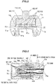
- the sliding surface 50e formed on the end surface of the flange portion 50b is made to come into contact with the sliding surface 40j formed on the lower portion of the middle stopper 40g serving as the rotation regulating portion illustrated in FIGS. 2A and 2B . That is, the sliding surface 40j and the sliding surface 50e function as rotation sliding surfaces in the direction of the longitudinal axis CL serving as the rotational axis when the distal end knob 50 (cap 60) is rotationally operated with respect to the middle 40 serving as the fixing portion.
- the rotation regulating portion e.g., the middle stopper surface 40k
- the rotation sliding surface e.g., the sliding surface 40j
Landscapes
- Engineering & Computer Science (AREA)
- Mechanical Engineering (AREA)
- Switches With Compound Operations (AREA)
- Rotary Switch, Piano Key Switch, And Lever Switch (AREA)
- Mechanical Control Devices (AREA)
Applications Claiming Priority (1)
| Application Number | Priority Date | Filing Date | Title |
|---|---|---|---|
| JP2015035194A JP6218188B2 (ja) | 2015-02-25 | 2015-02-25 | スイッチ装置 |
Publications (2)
| Publication Number | Publication Date |
|---|---|
| EP3061652A1 true EP3061652A1 (fr) | 2016-08-31 |
| EP3061652B1 EP3061652B1 (fr) | 2017-08-30 |
Family
ID=55699316
Family Applications (1)
| Application Number | Title | Priority Date | Filing Date |
|---|---|---|---|
| EP16157152.6A Active EP3061652B1 (fr) | 2015-02-25 | 2016-02-24 | Dispositif de commutation |
Country Status (4)
| Country | Link |
|---|---|
| US (1) | US9679717B2 (fr) |
| EP (1) | EP3061652B1 (fr) |
| JP (1) | JP6218188B2 (fr) |
| CN (1) | CN105914082B (fr) |
Families Citing this family (7)
| Publication number | Priority date | Publication date | Assignee | Title |
|---|---|---|---|---|
| JP6511332B2 (ja) * | 2015-05-13 | 2019-05-15 | 株式会社ヴァレオジャパン | 回転伝達機構、および回転伝達機構を採用したレバースイッチ |
| JP6632890B2 (ja) * | 2016-01-25 | 2020-01-22 | 古野電気株式会社 | 操作装置 |
| JP7029661B2 (ja) * | 2017-12-08 | 2022-03-04 | パナソニックIpマネジメント株式会社 | レバースイッチ装置 |
| WO2019111537A1 (fr) * | 2017-12-08 | 2019-06-13 | パナソニックIpマネジメント株式会社 | Dispositif commutateur à levier |
| JP7029660B2 (ja) * | 2017-12-08 | 2022-03-04 | パナソニックIpマネジメント株式会社 | レバースイッチ装置 |
| JP7598196B2 (ja) | 2020-01-10 | 2024-12-11 | キヤノンメディカルシステムズ株式会社 | X線診断装置及びx線診断装置用のコンソール装置 |
| CN116649799B (zh) * | 2023-01-16 | 2023-10-31 | 浙江山山家食品产业发展有限公司 | 糕点烘烤装置及烘烤工艺 |
Citations (5)
| Publication number | Priority date | Publication date | Assignee | Title |
|---|---|---|---|---|
| US5107243A (en) * | 1989-08-18 | 1992-04-21 | Alps Electric Co., Ltd. | Lever switch |
| WO1997020335A1 (fr) * | 1995-11-27 | 1997-06-05 | Kabushiki Kaisha Tokai-Rika-Denki-Seisakusho | Interrupteur a levier |
| JPH09198968A (ja) | 1996-01-18 | 1997-07-31 | Niles Parts Co Ltd | 自動車用複合スイッチレバー装置 |
| US5665948A (en) * | 1995-04-11 | 1997-09-09 | Niles Parts Co., Ltd. | Automobile knob switch |
| US6025564A (en) * | 1999-05-11 | 2000-02-15 | Eaton Corporation | Single stalk steering column switch |
Family Cites Families (3)
| Publication number | Priority date | Publication date | Assignee | Title |
|---|---|---|---|---|
| DE19631208A1 (de) * | 1996-08-02 | 1998-02-05 | Eaton Controls Gmbh | Lenkstockschalter für ein Kraftfahrzeug |
| JP2828045B2 (ja) * | 1996-08-02 | 1998-11-25 | 松下電器産業株式会社 | 車両用レバースイッチおよびその製造方法 |
| JP5752395B2 (ja) * | 2010-11-09 | 2015-07-22 | 矢崎総業株式会社 | 操作ユニット |
-
2015
- 2015-02-25 JP JP2015035194A patent/JP6218188B2/ja active Active
-
2016
- 2016-02-23 CN CN201610099000.0A patent/CN105914082B/zh active Active
- 2016-02-24 EP EP16157152.6A patent/EP3061652B1/fr active Active
- 2016-02-25 US US15/053,034 patent/US9679717B2/en active Active
Patent Citations (5)
| Publication number | Priority date | Publication date | Assignee | Title |
|---|---|---|---|---|
| US5107243A (en) * | 1989-08-18 | 1992-04-21 | Alps Electric Co., Ltd. | Lever switch |
| US5665948A (en) * | 1995-04-11 | 1997-09-09 | Niles Parts Co., Ltd. | Automobile knob switch |
| WO1997020335A1 (fr) * | 1995-11-27 | 1997-06-05 | Kabushiki Kaisha Tokai-Rika-Denki-Seisakusho | Interrupteur a levier |
| JPH09198968A (ja) | 1996-01-18 | 1997-07-31 | Niles Parts Co Ltd | 自動車用複合スイッチレバー装置 |
| US6025564A (en) * | 1999-05-11 | 2000-02-15 | Eaton Corporation | Single stalk steering column switch |
Also Published As
| Publication number | Publication date |
|---|---|
| EP3061652B1 (fr) | 2017-08-30 |
| US20160247644A1 (en) | 2016-08-25 |
| JP2016157615A (ja) | 2016-09-01 |
| JP6218188B2 (ja) | 2017-10-25 |
| CN105914082B (zh) | 2018-06-05 |
| CN105914082A (zh) | 2016-08-31 |
| US9679717B2 (en) | 2017-06-13 |
Similar Documents
| Publication | Publication Date | Title |
|---|---|---|
| EP3061652A1 (fr) | Dispositif de commutation | |
| EP3062325B1 (fr) | Dispositif de commutation | |
| EP3062324A1 (fr) | Dispositif de commutation | |
| JP6674540B2 (ja) | 車両用マルチオペレーティングスイッチユニット | |
| JPH11506992A (ja) | 方向指示キャンセル機構 | |
| KR20170051704A (ko) | 차량용 멀티 오퍼레이팅 스위치 유니트 | |
| US7482545B2 (en) | In-vehicle knob switch | |
| EP1312503B1 (fr) | Interrupteur à levier pour véhicule | |
| JP4695310B2 (ja) | 車両用レバースイッチ | |
| CN106133868A (zh) | 开关装置 | |
| KR20190071501A (ko) | 차량용 멀티 오퍼레이팅 스위치 유닛 | |
| KR101414293B1 (ko) | 차량용 레버 스위치 장치 | |
| US20250178659A1 (en) | Paddle switch | |
| KR102675895B1 (ko) | 차량용 멀티 오퍼레이팅 스위치 유니트 | |
| JP4289452B2 (ja) | コンビネーションスイッチ及びその組み付け装置 | |
| JPH11306924A (ja) | コンビネーションスイッチ | |
| JP2010049995A (ja) | スイッチ装置 | |
| KR100862003B1 (ko) | 레버 스위치 장치 | |
| JP2022127193A (ja) | レバースイッチ | |
| JP3717662B2 (ja) | レバーコンビネーションスイッチ | |
| JPH06302249A (ja) | レバースイッチ | |
| JPH11306926A (ja) | ウインカスイッチのキャンセル装置 | |
| JP2000173738A (ja) | 回転コネクタ | |
| JPH0658541U (ja) | レバースイッチ構造 |
Legal Events
| Date | Code | Title | Description |
|---|---|---|---|
| PUAI | Public reference made under article 153(3) epc to a published international application that has entered the european phase |
Free format text: ORIGINAL CODE: 0009012 |
|
| AK | Designated contracting states |
Kind code of ref document: A1 Designated state(s): AL AT BE BG CH CY CZ DE DK EE ES FI FR GB GR HR HU IE IS IT LI LT LU LV MC MK MT NL NO PL PT RO RS SE SI SK SM TR |
|
| AX | Request for extension of the european patent |
Extension state: BA ME |
|
| 17P | Request for examination filed |
Effective date: 20170228 |
|
| RBV | Designated contracting states (corrected) |
Designated state(s): AL AT BE BG CH CY CZ DE DK EE ES FI FR GB GR HR HU IE IS IT LI LT LU LV MC MK MT NL NO PL PT RO RS SE SI SK SM TR |
|
| GRAP | Despatch of communication of intention to grant a patent |
Free format text: ORIGINAL CODE: EPIDOSNIGR1 |
|
| INTG | Intention to grant announced |
Effective date: 20170519 |
|
| GRAS | Grant fee paid |
Free format text: ORIGINAL CODE: EPIDOSNIGR3 |
|
| GRAA | (expected) grant |
Free format text: ORIGINAL CODE: 0009210 |
|
| AK | Designated contracting states |
Kind code of ref document: B1 Designated state(s): AL AT BE BG CH CY CZ DE DK EE ES FI FR GB GR HR HU IE IS IT LI LT LU LV MC MK MT NL NO PL PT RO RS SE SI SK SM TR |
|
| REG | Reference to a national code |
Ref country code: GB Ref legal event code: FG4D |
|
| REG | Reference to a national code |
Ref country code: CH Ref legal event code: EP |
|
| REG | Reference to a national code |
Ref country code: AT Ref legal event code: REF Ref document number: 923180 Country of ref document: AT Kind code of ref document: T Effective date: 20170915 |
|
| REG | Reference to a national code |
Ref country code: IE Ref legal event code: FG4D |
|
| REG | Reference to a national code |
Ref country code: DE Ref legal event code: R096 Ref document number: 602016000303 Country of ref document: DE |
|
| REG | Reference to a national code |
Ref country code: NL Ref legal event code: MP Effective date: 20170830 |
|
| REG | Reference to a national code |
Ref country code: LT Ref legal event code: MG4D |
|
| REG | Reference to a national code |
Ref country code: AT Ref legal event code: MK05 Ref document number: 923180 Country of ref document: AT Kind code of ref document: T Effective date: 20170830 |
|
| PG25 | Lapsed in a contracting state [announced via postgrant information from national office to epo] |
Ref country code: FI Free format text: LAPSE BECAUSE OF FAILURE TO SUBMIT A TRANSLATION OF THE DESCRIPTION OR TO PAY THE FEE WITHIN THE PRESCRIBED TIME-LIMIT Effective date: 20170830 Ref country code: SE Free format text: LAPSE BECAUSE OF FAILURE TO SUBMIT A TRANSLATION OF THE DESCRIPTION OR TO PAY THE FEE WITHIN THE PRESCRIBED TIME-LIMIT Effective date: 20170830 Ref country code: NO Free format text: LAPSE BECAUSE OF FAILURE TO SUBMIT A TRANSLATION OF THE DESCRIPTION OR TO PAY THE FEE WITHIN THE PRESCRIBED TIME-LIMIT Effective date: 20171130 Ref country code: AT Free format text: LAPSE BECAUSE OF FAILURE TO SUBMIT A TRANSLATION OF THE DESCRIPTION OR TO PAY THE FEE WITHIN THE PRESCRIBED TIME-LIMIT Effective date: 20170830 Ref country code: HR Free format text: LAPSE BECAUSE OF FAILURE TO SUBMIT A TRANSLATION OF THE DESCRIPTION OR TO PAY THE FEE WITHIN THE PRESCRIBED TIME-LIMIT Effective date: 20170830 Ref country code: LT Free format text: LAPSE BECAUSE OF FAILURE TO SUBMIT A TRANSLATION OF THE DESCRIPTION OR TO PAY THE FEE WITHIN THE PRESCRIBED TIME-LIMIT Effective date: 20170830 |
|
| REG | Reference to a national code |
Ref country code: FR Ref legal event code: PLFP Year of fee payment: 3 |
|
| PG25 | Lapsed in a contracting state [announced via postgrant information from national office to epo] |
Ref country code: BG Free format text: LAPSE BECAUSE OF FAILURE TO SUBMIT A TRANSLATION OF THE DESCRIPTION OR TO PAY THE FEE WITHIN THE PRESCRIBED TIME-LIMIT Effective date: 20171130 Ref country code: LV Free format text: LAPSE BECAUSE OF FAILURE TO SUBMIT A TRANSLATION OF THE DESCRIPTION OR TO PAY THE FEE WITHIN THE PRESCRIBED TIME-LIMIT Effective date: 20170830 Ref country code: ES Free format text: LAPSE BECAUSE OF FAILURE TO SUBMIT A TRANSLATION OF THE DESCRIPTION OR TO PAY THE FEE WITHIN THE PRESCRIBED TIME-LIMIT Effective date: 20170830 Ref country code: GR Free format text: LAPSE BECAUSE OF FAILURE TO SUBMIT A TRANSLATION OF THE DESCRIPTION OR TO PAY THE FEE WITHIN THE PRESCRIBED TIME-LIMIT Effective date: 20171201 Ref country code: RS Free format text: LAPSE BECAUSE OF FAILURE TO SUBMIT A TRANSLATION OF THE DESCRIPTION OR TO PAY THE FEE WITHIN THE PRESCRIBED TIME-LIMIT Effective date: 20170830 Ref country code: IS Free format text: LAPSE BECAUSE OF FAILURE TO SUBMIT A TRANSLATION OF THE DESCRIPTION OR TO PAY THE FEE WITHIN THE PRESCRIBED TIME-LIMIT Effective date: 20171230 |
|
| PG25 | Lapsed in a contracting state [announced via postgrant information from national office to epo] |
Ref country code: NL Free format text: LAPSE BECAUSE OF FAILURE TO SUBMIT A TRANSLATION OF THE DESCRIPTION OR TO PAY THE FEE WITHIN THE PRESCRIBED TIME-LIMIT Effective date: 20170830 |
|
| PG25 | Lapsed in a contracting state [announced via postgrant information from national office to epo] |
Ref country code: DK Free format text: LAPSE BECAUSE OF FAILURE TO SUBMIT A TRANSLATION OF THE DESCRIPTION OR TO PAY THE FEE WITHIN THE PRESCRIBED TIME-LIMIT Effective date: 20170830 Ref country code: CZ Free format text: LAPSE BECAUSE OF FAILURE TO SUBMIT A TRANSLATION OF THE DESCRIPTION OR TO PAY THE FEE WITHIN THE PRESCRIBED TIME-LIMIT Effective date: 20170830 Ref country code: RO Free format text: LAPSE BECAUSE OF FAILURE TO SUBMIT A TRANSLATION OF THE DESCRIPTION OR TO PAY THE FEE WITHIN THE PRESCRIBED TIME-LIMIT Effective date: 20170830 Ref country code: PL Free format text: LAPSE BECAUSE OF FAILURE TO SUBMIT A TRANSLATION OF THE DESCRIPTION OR TO PAY THE FEE WITHIN THE PRESCRIBED TIME-LIMIT Effective date: 20170830 |
|
| PG25 | Lapsed in a contracting state [announced via postgrant information from national office to epo] |
Ref country code: EE Free format text: LAPSE BECAUSE OF FAILURE TO SUBMIT A TRANSLATION OF THE DESCRIPTION OR TO PAY THE FEE WITHIN THE PRESCRIBED TIME-LIMIT Effective date: 20170830 Ref country code: SM Free format text: LAPSE BECAUSE OF FAILURE TO SUBMIT A TRANSLATION OF THE DESCRIPTION OR TO PAY THE FEE WITHIN THE PRESCRIBED TIME-LIMIT Effective date: 20170830 Ref country code: SK Free format text: LAPSE BECAUSE OF FAILURE TO SUBMIT A TRANSLATION OF THE DESCRIPTION OR TO PAY THE FEE WITHIN THE PRESCRIBED TIME-LIMIT Effective date: 20170830 Ref country code: IT Free format text: LAPSE BECAUSE OF FAILURE TO SUBMIT A TRANSLATION OF THE DESCRIPTION OR TO PAY THE FEE WITHIN THE PRESCRIBED TIME-LIMIT Effective date: 20170830 |
|
| REG | Reference to a national code |
Ref country code: DE Ref legal event code: R097 Ref document number: 602016000303 Country of ref document: DE |
|
| PLBE | No opposition filed within time limit |
Free format text: ORIGINAL CODE: 0009261 |
|
| STAA | Information on the status of an ep patent application or granted ep patent |
Free format text: STATUS: NO OPPOSITION FILED WITHIN TIME LIMIT |
|
| 26N | No opposition filed |
Effective date: 20180531 |
|
| PG25 | Lapsed in a contracting state [announced via postgrant information from national office to epo] |
Ref country code: SI Free format text: LAPSE BECAUSE OF FAILURE TO SUBMIT A TRANSLATION OF THE DESCRIPTION OR TO PAY THE FEE WITHIN THE PRESCRIBED TIME-LIMIT Effective date: 20170830 |
|
| PG25 | Lapsed in a contracting state [announced via postgrant information from national office to epo] |
Ref country code: MC Free format text: LAPSE BECAUSE OF FAILURE TO SUBMIT A TRANSLATION OF THE DESCRIPTION OR TO PAY THE FEE WITHIN THE PRESCRIBED TIME-LIMIT Effective date: 20170830 |
|
| REG | Reference to a national code |
Ref country code: IE Ref legal event code: MM4A |
|
| REG | Reference to a national code |
Ref country code: BE Ref legal event code: MM Effective date: 20180228 |
|
| PG25 | Lapsed in a contracting state [announced via postgrant information from national office to epo] |
Ref country code: LU Free format text: LAPSE BECAUSE OF NON-PAYMENT OF DUE FEES Effective date: 20180224 |
|
| PG25 | Lapsed in a contracting state [announced via postgrant information from national office to epo] |
Ref country code: IE Free format text: LAPSE BECAUSE OF NON-PAYMENT OF DUE FEES Effective date: 20180224 |
|
| PG25 | Lapsed in a contracting state [announced via postgrant information from national office to epo] |
Ref country code: BE Free format text: LAPSE BECAUSE OF NON-PAYMENT OF DUE FEES Effective date: 20180228 |
|
| REG | Reference to a national code |
Ref country code: CH Ref legal event code: PL |
|
| PG25 | Lapsed in a contracting state [announced via postgrant information from national office to epo] |
Ref country code: LI Free format text: LAPSE BECAUSE OF NON-PAYMENT OF DUE FEES Effective date: 20190228 Ref country code: CH Free format text: LAPSE BECAUSE OF NON-PAYMENT OF DUE FEES Effective date: 20190228 |
|
| PG25 | Lapsed in a contracting state [announced via postgrant information from national office to epo] |
Ref country code: MT Free format text: LAPSE BECAUSE OF NON-PAYMENT OF DUE FEES Effective date: 20180224 |
|
| PG25 | Lapsed in a contracting state [announced via postgrant information from national office to epo] |
Ref country code: TR Free format text: LAPSE BECAUSE OF FAILURE TO SUBMIT A TRANSLATION OF THE DESCRIPTION OR TO PAY THE FEE WITHIN THE PRESCRIBED TIME-LIMIT Effective date: 20170830 |
|
| PGFP | Annual fee paid to national office [announced via postgrant information from national office to epo] |
Ref country code: GB Payment date: 20200212 Year of fee payment: 5 |
|
| PG25 | Lapsed in a contracting state [announced via postgrant information from national office to epo] |
Ref country code: PT Free format text: LAPSE BECAUSE OF FAILURE TO SUBMIT A TRANSLATION OF THE DESCRIPTION OR TO PAY THE FEE WITHIN THE PRESCRIBED TIME-LIMIT Effective date: 20170830 |
|
| PG25 | Lapsed in a contracting state [announced via postgrant information from national office to epo] |
Ref country code: MK Free format text: LAPSE BECAUSE OF NON-PAYMENT OF DUE FEES Effective date: 20170830 Ref country code: HU Free format text: LAPSE BECAUSE OF FAILURE TO SUBMIT A TRANSLATION OF THE DESCRIPTION OR TO PAY THE FEE WITHIN THE PRESCRIBED TIME-LIMIT; INVALID AB INITIO Effective date: 20160224 Ref country code: CY Free format text: LAPSE BECAUSE OF FAILURE TO SUBMIT A TRANSLATION OF THE DESCRIPTION OR TO PAY THE FEE WITHIN THE PRESCRIBED TIME-LIMIT Effective date: 20170830 |
|
| PGFP | Annual fee paid to national office [announced via postgrant information from national office to epo] |
Ref country code: FR Payment date: 20200113 Year of fee payment: 5 |
|
| PG25 | Lapsed in a contracting state [announced via postgrant information from national office to epo] |
Ref country code: AL Free format text: LAPSE BECAUSE OF FAILURE TO SUBMIT A TRANSLATION OF THE DESCRIPTION OR TO PAY THE FEE WITHIN THE PRESCRIBED TIME-LIMIT Effective date: 20170830 |
|
| GBPC | Gb: european patent ceased through non-payment of renewal fee |
Effective date: 20210224 |
|
| PG25 | Lapsed in a contracting state [announced via postgrant information from national office to epo] |
Ref country code: GB Free format text: LAPSE BECAUSE OF NON-PAYMENT OF DUE FEES Effective date: 20210224 Ref country code: FR Free format text: LAPSE BECAUSE OF NON-PAYMENT OF DUE FEES Effective date: 20210228 |
|
| PGFP | Annual fee paid to national office [announced via postgrant information from national office to epo] |
Ref country code: DE Payment date: 20260102 Year of fee payment: 11 |