EP3061950A2 - Moteur à combustion interne avec un vilebrequin fendu - Google Patents
Moteur à combustion interne avec un vilebrequin fendu Download PDFInfo
- Publication number
- EP3061950A2 EP3061950A2 EP16152383.2A EP16152383A EP3061950A2 EP 3061950 A2 EP3061950 A2 EP 3061950A2 EP 16152383 A EP16152383 A EP 16152383A EP 3061950 A2 EP3061950 A2 EP 3061950A2
- Authority
- EP
- European Patent Office
- Prior art keywords
- crankshaft
- portions
- engine
- cvt
- engine according
- Prior art date
- Legal status (The legal status is an assumption and is not a legal conclusion. Google has not performed a legal analysis and makes no representation as to the accuracy of the status listed.)
- Withdrawn
Links
- 238000002485 combustion reaction Methods 0.000 title claims abstract description 11
- 230000005540 biological transmission Effects 0.000 claims abstract description 27
- 230000008878 coupling Effects 0.000 claims abstract description 21
- 238000010168 coupling process Methods 0.000 claims abstract description 21
- 238000005859 coupling reaction Methods 0.000 claims abstract description 21
- 238000000034 method Methods 0.000 claims abstract description 19
- 239000003054 catalyst Substances 0.000 claims description 8
- 230000007246 mechanism Effects 0.000 claims description 8
- 230000001360 synchronised effect Effects 0.000 claims description 5
- 238000006073 displacement reaction Methods 0.000 claims description 3
- 230000002706 hydrostatic effect Effects 0.000 claims description 3
- 230000009849 deactivation Effects 0.000 abstract description 3
- 230000008929 regeneration Effects 0.000 abstract description 2
- 238000011069 regeneration method Methods 0.000 abstract description 2
- 230000000694 effects Effects 0.000 description 11
- 230000008859 change Effects 0.000 description 5
- 239000010705 motor oil Substances 0.000 description 5
- 230000009471 action Effects 0.000 description 3
- 238000001816 cooling Methods 0.000 description 3
- 239000007789 gas Substances 0.000 description 2
- 238000005461 lubrication Methods 0.000 description 2
- 230000007704 transition Effects 0.000 description 2
- 230000001133 acceleration Effects 0.000 description 1
- 238000006243 chemical reaction Methods 0.000 description 1
- 238000001514 detection method Methods 0.000 description 1
- 230000009977 dual effect Effects 0.000 description 1
- 238000010304 firing Methods 0.000 description 1
- 238000009499 grossing Methods 0.000 description 1
- 238000005086 pumping Methods 0.000 description 1
- 238000000926 separation method Methods 0.000 description 1
Images


Classifications
-
- F—MECHANICAL ENGINEERING; LIGHTING; HEATING; WEAPONS; BLASTING
- F02—COMBUSTION ENGINES; HOT-GAS OR COMBUSTION-PRODUCT ENGINE PLANTS
- F02D—CONTROLLING COMBUSTION ENGINES
- F02D17/00—Controlling engines by cutting out individual cylinders; Rendering engines inoperative or idling
- F02D17/02—Cutting-out
-
- F—MECHANICAL ENGINEERING; LIGHTING; HEATING; WEAPONS; BLASTING
- F16—ENGINEERING ELEMENTS AND UNITS; GENERAL MEASURES FOR PRODUCING AND MAINTAINING EFFECTIVE FUNCTIONING OF MACHINES OR INSTALLATIONS; THERMAL INSULATION IN GENERAL
- F16H—GEARING
- F16H15/00—Gearings for conveying rotary motion with variable gear ratio, or for reversing rotary motion, by friction between rotary members
- F16H15/02—Gearings for conveying rotary motion with variable gear ratio, or for reversing rotary motion, by friction between rotary members without members having orbital motion
- F16H15/04—Gearings providing a continuous range of gear ratios
-
- F—MECHANICAL ENGINEERING; LIGHTING; HEATING; WEAPONS; BLASTING
- F02—COMBUSTION ENGINES; HOT-GAS OR COMBUSTION-PRODUCT ENGINE PLANTS
- F02B—INTERNAL-COMBUSTION PISTON ENGINES; COMBUSTION ENGINES IN GENERAL
- F02B73/00—Combinations of two or more engines, not otherwise provided for
-
- F—MECHANICAL ENGINEERING; LIGHTING; HEATING; WEAPONS; BLASTING
- F02—COMBUSTION ENGINES; HOT-GAS OR COMBUSTION-PRODUCT ENGINE PLANTS
- F02D—CONTROLLING COMBUSTION ENGINES
- F02D17/00—Controlling engines by cutting out individual cylinders; Rendering engines inoperative or idling
-
- F—MECHANICAL ENGINEERING; LIGHTING; HEATING; WEAPONS; BLASTING
- F16—ENGINEERING ELEMENTS AND UNITS; GENERAL MEASURES FOR PRODUCING AND MAINTAINING EFFECTIVE FUNCTIONING OF MACHINES OR INSTALLATIONS; THERMAL INSULATION IN GENERAL
- F16H—GEARING
- F16H15/00—Gearings for conveying rotary motion with variable gear ratio, or for reversing rotary motion, by friction between rotary members
- F16H15/48—Gearings for conveying rotary motion with variable gear ratio, or for reversing rotary motion, by friction between rotary members with members having orbital motion
-
- F—MECHANICAL ENGINEERING; LIGHTING; HEATING; WEAPONS; BLASTING
- F16—ENGINEERING ELEMENTS AND UNITS; GENERAL MEASURES FOR PRODUCING AND MAINTAINING EFFECTIVE FUNCTIONING OF MACHINES OR INSTALLATIONS; THERMAL INSULATION IN GENERAL
- F16H—GEARING
- F16H3/00—Toothed gearings for conveying rotary motion with variable gear ratio or for reversing rotary motion
- F16H3/44—Toothed gearings for conveying rotary motion with variable gear ratio or for reversing rotary motion using gears having orbital motion
- F16H3/72—Toothed gearings for conveying rotary motion with variable gear ratio or for reversing rotary motion using gears having orbital motion with a secondary drive, e.g. regulating motor, in order to vary speed continuously
- F16H3/724—Toothed gearings for conveying rotary motion with variable gear ratio or for reversing rotary motion using gears having orbital motion with a secondary drive, e.g. regulating motor, in order to vary speed continuously using externally powered electric machines
-
- F—MECHANICAL ENGINEERING; LIGHTING; HEATING; WEAPONS; BLASTING
- F16—ENGINEERING ELEMENTS AND UNITS; GENERAL MEASURES FOR PRODUCING AND MAINTAINING EFFECTIVE FUNCTIONING OF MACHINES OR INSTALLATIONS; THERMAL INSULATION IN GENERAL
- F16H—GEARING
- F16H37/00—Combinations of mechanical gearings, not provided for in groups F16H1/00 - F16H35/00
- F16H37/02—Combinations of mechanical gearings, not provided for in groups F16H1/00 - F16H35/00 comprising essentially only toothed or friction gearings
- F16H37/021—Combinations of mechanical gearings, not provided for in groups F16H1/00 - F16H35/00 comprising essentially only toothed or friction gearings toothed gearing combined with continuously variable friction gearing
-
- F—MECHANICAL ENGINEERING; LIGHTING; HEATING; WEAPONS; BLASTING
- F16—ENGINEERING ELEMENTS AND UNITS; GENERAL MEASURES FOR PRODUCING AND MAINTAINING EFFECTIVE FUNCTIONING OF MACHINES OR INSTALLATIONS; THERMAL INSULATION IN GENERAL
- F16H—GEARING
- F16H47/00—Combinations of mechanical gearing with fluid clutches or fluid gearing
- F16H47/02—Combinations of mechanical gearing with fluid clutches or fluid gearing the fluid gearing being of the volumetric type
Definitions
- the present disclosure relates to a split crankshaft of, for example, an internal combustion engine and particularly, but not exclusively, to an apparatus and method for connection of a split crankshaft by variable transmission and clutch means. Aspects of the invention relate to an engine, to a method and to a vehicle.
- US4069803A (General Motors Corporation) discloses a clutch mechanism which is located between portions of a split crankshaft in an internal combustion engine and which allows a portion of the engine to be stopped and the remaining portion to supply power to drive a motor vehicle.
- Several other mechanisms have previously been published which allow for connection and disconnection of a partitioned or split crankshaft and control the relative position when connected in order to provide a regular torque output from the engine.
- Embodiments of the invention may enable a smooth transition from a disconnected condition of a split crankshaft to a connected condition and achieve the correct angular relationship between crankshaft portions when connected.
- the control of secondary systems, including valve actuation and balancer shafts, is also considered for synchronisation with the crankshaft connection or disconnection.
- aspects of the present invention relate to a drive mechanism for controlling the relative rotation of the portions of a split crankshaft in an internal combustion engine, a variable balancer shaft and a method for control of a continuously variable valve system for an internal combustion engine.
- an internal combustion engine comprising: a crankshaft comprising at least first and second portions; coupling means for selectively coupling the first and second portions together; and transmission means operable to synchronise connection of said first and second portions.
- This apparatus may allow deactivation of a number of cylinders while the remaining cylinders provide torque to the flywheel. Additionally, synchronisation of the two portions of said crankshaft during connection or disconnection may be facilitated by the use of a CVT as the transmission means.
- a CVT as the transmission means.
- a six cylinder engine may have a crankshaft in two portions, each connected to three pistons. This would allow the engine to operate as a three or six cylinder unit. When the engine operates in the three cylinder mode, the inactive cylinders would be allowed to stop and the frictional losses associated with these cylinders would be removed.
- Various engine configurations may allow various modes of operation with some cylinders active and others inactive. Additionally, the synchronisation apparatus may be applied one or more times to an engine.
- the coupling means may comprise a clutch such as a friction or dog clutch. This may allow transmission of driving torque without the use of the CVT. Because the CVT is required to transmit synchronisation torque rather than full drive torque, the size, weight and torque capacity of the CVT may be reduced.
- CVT apparatus are available with configurations which have either coaxial or offset input and output axes.
- the apparatus may optionally comprise any CVT mechanism with the location of the variator (ratio varying apparatus) aligned with the crankshaft axis, an offset parallel axis or both.
- the input to the variator may be directly driven from one portion of the crankshaft or may be driveably connected through gears or an endless drive such as a chain or belt.
- the output from the variator may directly drive another portion of the crankshaft or may be driveably connected through gears or an endless drive such as a chain or belt.
- CVT transmissions are well known with drive mechanisms employing rollers, spheres, belts, chains, gears, magnets, hydrodynamic or hydrostatic means.
- the apparatus may comprise a hydrostatic CVT consisting of a hydraulic pump driveably connected to the permanently driving crankshaft portion and a variable displacement hydraulic motor driveably connected to another crankshaft portion.
- the hydraulic pump may also be used as an engine oil pump to provide lubrication and cooling flow of engine oil and may also have variable displacement.
- the hydraulic motor may be configured to supply engine oil for lubrication and cooling in addition to another engine oil pump.
- this may allow said engine oil pump to be a smaller size or more efficient in operation because it no longer needs to fulfil the entire performance envelope.
- the apparatus may comprise an electrically driven powersplit transmission configured as the CVT to synchronise the crankshaft portions.
- Powersplit transmissions are known within the context of automotive transmissions and may comprise epicyclic, bevel or magnetic gearing.
- the powersplit may comprise an epicyclic gear with connections to the two crankshaft parts and an electric machine.
- the epicyclic gearset imposes a speed balance between three elements (a sun gear, one or more planet gears supported on a carrier and an annular gear). By enforcing a speed on one of the elements by control of the electric machine, the speed ratio of the remaining two is fixed. This configuration may support the synchronisation and positional alignment of the crankshaft portions.
- the speeds of the remaining two elements are no longer controlled and may be allowed to diverge.
- the inactive part of the crank may be stationary and the active part rotating. In this state the electric machine will be freely rotating at a speed between the two crank parts, the exact speed being calculated by the ratio of gear teeth. By energising the electric machine and controlling it to match the speed of the active part of the crank, it will drive the inactive part to also match the speed of the active part.
- the apparatus may comprise a secondary connection such as a dog clutch, spline or other torque connection.
- This secondary connection may provide a positive link between the crankshaft portions maintaining relative rotational position and allowing high torque transfer when the engine is required to supply drive torque across the connection.
- locking this connection may additionally allow electrical drive or electrical regeneration from the engine, vehicle or both.
- the apparatus may include one or more exhaust catalysts in order to reduce emission of undesirable gases.
- the exhaust paths from groups of cylinders associated with the portions of the crankshaft may be separately routed to portions of the catalyst and may be combined after the catalyst. This separation allows the exhaust gases to interact with an appropriately configured catalyst in the cases where the crankshaft is connected or disconnected. For example, this may allow a smaller catalyst to be active when a reduced number of cylinders are active, improving warm up time and catalyst temperature.
- the apparatus may comprise a four stroke engine
- the apparatus may comprise a two stroke or rotary engine. It is also possible to combine differing engine cycles or configurations with the ability to connect or disconnect the linking crankshaft. For example one or more four stroke cylinders may be engaged for drive through a portion of the crankshaft and assisted at high load by one or more two stroke cylinders through another portion of the crankshaft and it will be apparent that various other combinations are possible.
- the apparatus may include one or more balancer shafts which may be driveably connected to the portions of the crankshaft. It will be apparent to a person skilled in the art that the disconnection of a portion of the crankshaft will change the engine balance and in general a reduced number of active cylinders will degrade the engine balance. The increased balance compensation required when portion of the crankshaft is disconnected would conventionally require the connection of an additional synchronised balancer shaft as the crankshaft coupling is disconnected.
- the balancer shaft or shafts may be permanently connected, but the action of the eccentric mass or masses may be modified by variation of their active radius. The actuation of this apparatus may be linked to the connection of the crankshaft or independently controlled.
- a balancer mass may be provided on a shaft rotating in a geared relationship with the crankshaft.
- this balancer mass its position relative to the rotating axis of its supporting shaft may be modified. So, if the balancer mass were moved to a small radius its effect would reduce. Alternatively, moving the balancer mass to a larger radius would increase its effect.
- This effect may be achieved by pivotally mounting the balancer mass to the balancer shaft and enforcing a change to the angle of the pivot. For example, if the angle of the pivot were 90° then the balancer mass would have a maximum effect whereas if the angle of the pivot were 0° then the balancer mass would have minimal effect.
- a method of controlling a CVT to smoothly accelerate a stationary crankshaft portion to closely match speed and relative position with a rotating crankshaft portion.
- Separate encoders or a differential encoder may be provided for the two portions of the crankshaft to provide speed and position information to a controller.
- the controller then actuates the apparatus to change the variator ratio and achieve the synchronisation of the crankshaft.
- the coupling means may be brought into engagement in order to maintain synchronisation.
- variable lift valves which may consist of conventional control for the valves operating the running portion of the engine and different operational modes for the portion of the valvetrain associated with the disconnected portion of the crankshaft.
- the modes of operation may include reducing the lift of the valves associated with the disconnected portion of the crankshaft. In this condition the actuation of some valves may not be synchronised with the piston movement and so valve contact with the piston may occur at full lift. Reducing the lift of the relevant valves may mitigate this error state and avoid the need for one or more secondary camshafts and associated drive apparatus.
- the modes of operation may optionally extend the valve opening duration even to the extent of maintaining a small opening over a complete cycle of the crankshaft in order to reduce pumping reaction.
- This mode may be appropriate when the disconnected portion of the crankshaft is being accelerated.
- a further mode of operation may be to close one or more valves associated with the disconnected portion of the crankshaft. This mode may be used to reduce any undesirable cooling effect on deactivated cylinders and also more quickly slow the disconnected portion of the crankshaft.
- a method may be provided to control a secondary coupling, such as a dog clutch or friction clutch, in order to maintain the positional alignment of the crankshaft portions when the portions have been synchronised.
- a secondary coupling such as a dog clutch or friction clutch
- This may advantageously allow the use of a CVT with low torque capacity and associated higher control accuracy while the secondary coupling is able to transmit the required torque at high engine load. Because the synchronisation of the crankshaft portions is achieved by the CVT, it is not necessary for the coupling to provide this function although it may be advantageous.
- an electrical powersplit CVT may be controlled in conjunction with the operation of a secondary coupling.
- the electric machine may provide control of the synchronisation of the crankshaft portions when the secondary coupling is disconnected.
- the electric machine is then connected to the crankshaft and may be used to provide additional drive through the crankshaft.
- the electric machine may also be used to provide electrical generation taking drive from the crankshaft.
- a method may be provided to control the position of one or more balance weights on one or more balancer shafts.
- the method may include the detection of the balance requirement based on the connection status of the crankshaft and control of an actuator to change the acting radius of one or more balance weights.
- the method may further detect engine vibration caused by poor balance and control the position of one or more balance weights in order to improve overall balance and reduce associated engine vibration.
- Operation of the balance weights may be independently controlled by an electronic control unit or be linked to the control of other apparatus.
- the actuation of one or more balance weights may be hydraulically controlled using a control pressure linked to the actuation of the secondary coupling.
- 'flywheel' may not be strictly appropriate to all engines. For example, drive from an engine to an automatic transmission will conventionally be transmitted through a flexplate to the torque converter with no flywheel. In this application the term 'flywheel' is intended to describe either a single or dual mass flywheel or a flexplate.
- CVT continuously variable transmission
- IVVT infinitely variable transmission
- the CVT transmission may require a starting device such as a clutch to encourage a stationary member to begin to rotate.
- CVT is therefore intended to describe either a CVT transmission including a starting device or an IVT.
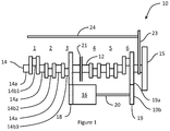
- the crankshaft comprises two coaxial portions 12,14.
- a first 'active' portion 12 of the crankshaft is associated with cylinders 4-6 of the engine (cylinders, connecting rods and pistons are not shown) and is driveably connected to a flywheel 15 configured to supply drive torque to a transmission.
- a second "passive" portion 14 of the crankshaft is similarly associated with cylinders 1 to 3 and is configured to be selectively disconnected from the first portion 12 so as to permit the deactivation of the associated cylinders 1-3.
- the second portion of the crankshaft 14 comprises a number of main bearing journals 14a and throws 14b1-14b3.
- crankshaft portion is thus constrained to rotate about the main bearing journals 14a and the connecting rod for piston 1 (not shown) is rotatably connected to throw 14b1.
- connecting rods for cylinders 2 and 3 are respectively connected to throws 14b2 and 14b3.
- the first portion of the crankshaft 12 is similarly configured. Disconnection of these cylinders allows them to cease rotation and so reduces the frictional losses associated with their movement.
- disconnection of the second portion 14 provides improved efficiency while meeting the driver demand.
- a CVT transmission 16 is configured to connect the first portion 12 of the crankshaft to the second portion 14 through gear trains 18, 19 and a shaft 20.
- Gear trains 18 and 19 may each comprise a first gear connected and concentrically mounted to the respective crankshaft portion 12, 14 and a second gear connected and concentrically mounted to the CVT 16 or shaft 20.
- gear train 19 comprises a first gear 19a connected to the first crankshaft portion 12 and a second gear 19b connected to the shaft 20.
- Gear trains 18 and 19 may comprise further idler gears and may have differing ratios.
- the transmission 16 is arranged to synchronise the two portions 12, 14 of the crankshaft and may be separate from a transmission driven through the flywheel 15 and providing drive to one or more wheels of the vehicle.
- a secondary connection is provided between the portions 12, 14 of the crankshaft.
- This secondary connection consists of a clutch 21 able to transmit the torque generated by cylinders 1-3 into the first portion of the crankshaft.
- the clutch 21 allows the CVT 16 to be reduced in size and weight and provides an efficient coupling between the crankshaft portions 12, 14. Because the CVT 16 is required to transmit synchronisation torque rather than full drive torque, its size, weight and torque capacity may be reduced. Losses associated with the CVT 16 and gear trains 18 and 19 may be reduced by the transmission of drive torque through the clutch 21 rather than the CVT 16, thereby improving efficiency.
- a drive mechanism 23 such as a belt, chain or gear train for one or more camshafts 24 is provided and the valves are conventionally controlled through a variable valve lift system.
- a variable valve lift system In the case of a six-cylinder, in-line engine, it is conventional to provide separate camshafts for inlet and exhaust valves and embodiments of the present invention may make use of this system with an enhanced control method to vary the valve lift to the disconnected portion of the crankshaft.
- one or more valves may be operated with reduced lift or duration in order to reduce the air mass contained in the cylinders.
- individual cylinders may be configured to contain different air masses in order to encourage the second crank portion 14 to stop in a specific angular position. This may also allow air to be entrapped in some cylinders, improving start time.
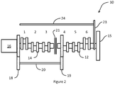
- the CVT 16 is located coaxially with the crankshaft parts 12, 14 providing synchronising drive through gear trains 18, 19 and a shaft 20 substantially parallel to the crankshaft. Operation of this embodiment is substantially identical to that of Figure 1 .
- the CVT or IVT (16) is configured with its input and output on different, substantially parallel axes.
- the synchronising drive between the crankshaft portions 12, 14 is then achieved through a shaft 20 and gears 19. Again, operation of this embodiment is substantially identical to that of Figure 1 .
- the synchronisation shaft 20 is additionally used to improve engine balance. This requires a 1:1 gear ratio for drive gears 19 so the shaft 20 turns at the same speed as the crankshaft in the opposite direction.
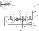
- a balance mass 33 is attached to the balancer shaft 20 by a hinged connection 32 in order to vary the radius of action of the balance weight.
- the hinged connection is connected to a sleeve 30 by a link 31. The sleeve 30 may then be actuated to move in the direction of arrow A and the balance mass 33 will then rotate in the direction of arrow B about the hinge 32 to a reduced radius of action.
- FIG. 4a shows the balance mass 33 in the actuated position where it has minimal balancing effect. In this position, sleeve 30 has moved to the left along shaft 20. This pulls link 31 which rotates the balance mass 33 about pivot 32. The balance mass 33 is now shown in a location concentric with balancer shaft 20.
- the CVT or IVT 16 consists of a power split arrangement including an electric machine 35 driving the carrier 34 of an epicyclic gearset.
- the carrier 34 supports planet gears 37 which mesh with a sun gear 36 and annulus 38 in a conventional manner.
- the sun gear 38 is driveably attached to the second crankshaft portion 14 and the annulus is geared through a shaft 20 and gearsets 18, 19 connecting to the first crankshaft portion 12.
- the electric machine is able to control the relative speed between the portions of the crankshaft.
- the electric machine 35 may be used as a motor or generator attached to the crankshaft.
- crankshaft portions 12, 14 are substantially parallel in a vee configuration engine. Transfer gears 39 are provided to connect the portions 12, 14 together and a clutch 21 is provided for disconnection of one portion.
- the CVT 16 connects between the crankshaft portions 12, 14 and is able to control the relative speed thereof.
- Figure 7 shows a schematic plan view of a vehicle 1 comprising a powertrain with an engine 10 according to an embodiment.
Landscapes
- Engineering & Computer Science (AREA)
- General Engineering & Computer Science (AREA)
- Mechanical Engineering (AREA)
- Chemical & Material Sciences (AREA)
- Combustion & Propulsion (AREA)
- Transmission Devices (AREA)
- Valve Device For Special Equipments (AREA)
Applications Claiming Priority (1)
| Application Number | Priority Date | Filing Date | Title |
|---|---|---|---|
| GB1501999.5A GB2534924B (en) | 2015-02-06 | 2015-02-06 | Split crankshaft with portions synchronized by a transmission |
Publications (2)
| Publication Number | Publication Date |
|---|---|
| EP3061950A2 true EP3061950A2 (fr) | 2016-08-31 |
| EP3061950A3 EP3061950A3 (fr) | 2016-11-16 |
Family
ID=52746247
Family Applications (1)
| Application Number | Title | Priority Date | Filing Date |
|---|---|---|---|
| EP16152383.2A Withdrawn EP3061950A3 (fr) | 2015-02-06 | 2016-01-22 | Moteur à combustion interne avec un vilebrequin fendu |
Country Status (2)
| Country | Link |
|---|---|
| EP (1) | EP3061950A3 (fr) |
| GB (1) | GB2534924B (fr) |
Cited By (2)
| Publication number | Priority date | Publication date | Assignee | Title |
|---|---|---|---|---|
| FR3083267A1 (fr) * | 2018-06-27 | 2020-01-03 | Renault S.A.S | Desactivation de cylindres de moteur thermique |
| CN117846790A (zh) * | 2024-03-06 | 2024-04-09 | 四川迅联达智能科技有限公司 | 一种活塞式发动机的变缸装置及变缸数系统 |
Family Cites Families (3)
| Publication number | Priority date | Publication date | Assignee | Title |
|---|---|---|---|---|
| DE3005343A1 (de) * | 1980-02-13 | 1981-08-20 | LuK Lamellen und Kupplungsbau GmbH, 7580 Bühl | Verfahren zum wahlweisen an- und abkuppeln von kurbelwellen |
| EP0184685A3 (fr) * | 1984-12-13 | 1987-04-08 | KANIUT, Herbert Maximilian | Moteur divisé avec vilebrequin divisé et un arbre-machine transversal pour l'entraínement des auxiliaires |
| DE102010007996B4 (de) * | 2010-02-15 | 2018-08-16 | Audi Ag | Kraftwagen sowie Verfahren zum Betreiben eines Antriebsstrangs eines Kraftwagens |
-
2015
- 2015-02-06 GB GB1501999.5A patent/GB2534924B/en active Active
-
2016
- 2016-01-22 EP EP16152383.2A patent/EP3061950A3/fr not_active Withdrawn
Cited By (3)
| Publication number | Priority date | Publication date | Assignee | Title |
|---|---|---|---|---|
| FR3083267A1 (fr) * | 2018-06-27 | 2020-01-03 | Renault S.A.S | Desactivation de cylindres de moteur thermique |
| CN117846790A (zh) * | 2024-03-06 | 2024-04-09 | 四川迅联达智能科技有限公司 | 一种活塞式发动机的变缸装置及变缸数系统 |
| CN117846790B (zh) * | 2024-03-06 | 2024-05-28 | 四川迅联达智能科技有限公司 | 一种活塞式发动机的变缸装置及变缸数系统 |
Also Published As
| Publication number | Publication date |
|---|---|
| EP3061950A3 (fr) | 2016-11-16 |
| GB2534924A (en) | 2016-08-10 |
| GB2534924B (en) | 2017-12-13 |
| GB201501999D0 (en) | 2015-03-25 |
Similar Documents
| Publication | Publication Date | Title |
|---|---|---|
| US11364784B2 (en) | Transmission for a motor vehicle, motor vehicle powertrain comprising said transmission, and method for operating the transmission | |
| CN101293476B (zh) | 具有反转发动机的混合动力系统 | |
| CN203511265U (zh) | 具有内燃发动机和起动机发电机的机动车辆的动力传动系 | |
| CN103118891B (zh) | 用于机动车辆的电驱动器 | |
| US7731617B2 (en) | Automated motor vehicle transmission and method of operating the same | |
| CN111823846B (zh) | 带有爪式离合器装置的多模式集成式启动机-发电机装置 | |
| WO2011138892A1 (fr) | Système de propulsion de véhicule hybride | |
| EP2383140A1 (fr) | Dispositif de transmission de puissance pour véhicule hybride | |
| US10384529B2 (en) | Power transmission apparatus for hybrid electric vehicle | |
| CN111828223B (zh) | 带有凸轮装置的多模式集成式启动机-发电机装置 | |
| US9334939B2 (en) | Power split transmission of a traction drive of a vehicle | |
| JP2000343966A (ja) | ドライブトレイン | |
| US20160305513A1 (en) | Accessory devices drive system | |
| WO2007138353A2 (fr) | Système de freinage régénérateur | |
| US10132397B2 (en) | Driving device and work machine device | |
| KR20150113968A (ko) | 오일 공급 장치 | |
| JP2004222435A (ja) | 電気自動車の駆動装置 | |
| US20130281244A1 (en) | Cold start clutch for cvt transmission | |
| US10641373B2 (en) | Power-split continuously variable transmission device | |
| CN107250484A (zh) | 内燃机 | |
| EP3061950A2 (fr) | Moteur à combustion interne avec un vilebrequin fendu | |
| EP3327310B1 (fr) | Un ensemble moteur a combustion avec arbres d'equilibrage utilisant des moteurs electriques | |
| CN102673557B (zh) | 具发动机、电机和它们间的行星传动机构的布置结构以及改变这种布置结构运行方式的方法 | |
| CN111712392B (zh) | 模块化的驱动组件 | |
| JP2012233573A (ja) | 振動補償装置 |
Legal Events
| Date | Code | Title | Description |
|---|---|---|---|
| PUAI | Public reference made under article 153(3) epc to a published international application that has entered the european phase |
Free format text: ORIGINAL CODE: 0009012 |
|
| AK | Designated contracting states |
Kind code of ref document: A2 Designated state(s): AL AT BE BG CH CY CZ DE DK EE ES FI FR GB GR HR HU IE IS IT LI LT LU LV MC MK MT NL NO PL PT RO RS SE SI SK SM TR |
|
| AX | Request for extension of the european patent |
Extension state: BA ME |
|
| PUAL | Search report despatched |
Free format text: ORIGINAL CODE: 0009013 |
|
| AK | Designated contracting states |
Kind code of ref document: A3 Designated state(s): AL AT BE BG CH CY CZ DE DK EE ES FI FR GB GR HR HU IE IS IT LI LT LU LV MC MK MT NL NO PL PT RO RS SE SI SK SM TR |
|
| AX | Request for extension of the european patent |
Extension state: BA ME |
|
| RIC1 | Information provided on ipc code assigned before grant |
Ipc: F16H 3/72 20060101ALN20161011BHEP Ipc: F16H 37/02 20060101ALN20161011BHEP Ipc: F16H 47/02 20060101ALN20161011BHEP Ipc: F02D 17/02 20060101AFI20161011BHEP |
|
| 17P | Request for examination filed |
Effective date: 20170516 |
|
| RBV | Designated contracting states (corrected) |
Designated state(s): AL AT BE BG CH CY CZ DE DK EE ES FI FR GB GR HR HU IE IS IT LI LT LU LV MC MK MT NL NO PL PT RO RS SE SI SK SM TR |
|
| STAA | Information on the status of an ep patent application or granted ep patent |
Free format text: STATUS: THE APPLICATION HAS BEEN WITHDRAWN |
|
| 18W | Application withdrawn |
Effective date: 20181220 |