EP3062171B1 - Armbanduhrgehäuse aus plastik oder galvanoplastisch erzeugtem material mit abnehmbarem uhrenglas - Google Patents
Armbanduhrgehäuse aus plastik oder galvanoplastisch erzeugtem material mit abnehmbarem uhrenglas Download PDFInfo
- Publication number
- EP3062171B1 EP3062171B1 EP15156978.7A EP15156978A EP3062171B1 EP 3062171 B1 EP3062171 B1 EP 3062171B1 EP 15156978 A EP15156978 A EP 15156978A EP 3062171 B1 EP3062171 B1 EP 3062171B1
- Authority
- EP
- European Patent Office
- Prior art keywords
- crystal
- case
- stop means
- angular
- case middle
- Prior art date
- Legal status (The legal status is an assumption and is not a legal conclusion. Google has not performed a legal analysis and makes no representation as to the accuracy of the status listed.)
- Active
Links
Images




Classifications
-
- G—PHYSICS
- G04—HOROLOGY
- G04B—MECHANICALLY-DRIVEN CLOCKS OR WATCHES; MECHANICAL PARTS OF CLOCKS OR WATCHES IN GENERAL; TIME PIECES USING THE POSITION OF THE SUN, MOON OR STARS
- G04B37/00—Cases
- G04B37/0008—Cases for pocket watches and wrist watches
-
- G—PHYSICS
- G04—HOROLOGY
- G04B—MECHANICALLY-DRIVEN CLOCKS OR WATCHES; MECHANICAL PARTS OF CLOCKS OR WATCHES IN GENERAL; TIME PIECES USING THE POSITION OF THE SUN, MOON OR STARS
- G04B37/00—Cases
- G04B37/08—Hermetic sealing of openings, joints, passages or slits
- G04B37/11—Hermetic sealing of openings, joints, passages or slits of the back cover of pocket or wrist watches
-
- G—PHYSICS
- G04—HOROLOGY
- G04B—MECHANICALLY-DRIVEN CLOCKS OR WATCHES; MECHANICAL PARTS OF CLOCKS OR WATCHES IN GENERAL; TIME PIECES USING THE POSITION OF THE SUN, MOON OR STARS
- G04B37/00—Cases
- G04B37/22—Materials or processes of manufacturing pocket watch or wrist watch cases
- G04B37/225—Non-metallic cases
-
- G—PHYSICS
- G04—HOROLOGY
- G04B—MECHANICALLY-DRIVEN CLOCKS OR WATCHES; MECHANICAL PARTS OF CLOCKS OR WATCHES IN GENERAL; TIME PIECES USING THE POSITION OF THE SUN, MOON OR STARS
- G04B37/00—Cases
- G04B37/22—Materials or processes of manufacturing pocket watch or wrist watch cases
- G04B37/225—Non-metallic cases
- G04B37/226—Non-metallic cases coated with a metallic layer
-
- G—PHYSICS
- G04—HOROLOGY
- G04B—MECHANICALLY-DRIVEN CLOCKS OR WATCHES; MECHANICAL PARTS OF CLOCKS OR WATCHES IN GENERAL; TIME PIECES USING THE POSITION OF THE SUN, MOON OR STARS
- G04B39/00—Watch crystals; Fastening or sealing of crystals; Clock glasses
-
- G—PHYSICS
- G04—HOROLOGY
- G04B—MECHANICALLY-DRIVEN CLOCKS OR WATCHES; MECHANICAL PARTS OF CLOCKS OR WATCHES IN GENERAL; TIME PIECES USING THE POSITION OF THE SUN, MOON OR STARS
- G04B39/00—Watch crystals; Fastening or sealing of crystals; Clock glasses
- G04B39/004—Watch crystals; Fastening or sealing of crystals; Clock glasses from a material other than glass
-
- G—PHYSICS
- G04—HOROLOGY
- G04B—MECHANICALLY-DRIVEN CLOCKS OR WATCHES; MECHANICAL PARTS OF CLOCKS OR WATCHES IN GENERAL; TIME PIECES USING THE POSITION OF THE SUN, MOON OR STARS
- G04B39/00—Watch crystals; Fastening or sealing of crystals; Clock glasses
- G04B39/02—Sealing crystals or glasses
-
- G—PHYSICS
- G04—HOROLOGY
- G04B—MECHANICALLY-DRIVEN CLOCKS OR WATCHES; MECHANICAL PARTS OF CLOCKS OR WATCHES IN GENERAL; TIME PIECES USING THE POSITION OF THE SUN, MOON OR STARS
- G04B43/00—Protecting clockworks by shields or other means against external influences, e.g. magnetic fields
-
- G—PHYSICS
- G04—HOROLOGY
- G04B—MECHANICALLY-DRIVEN CLOCKS OR WATCHES; MECHANICAL PARTS OF CLOCKS OR WATCHES IN GENERAL; TIME PIECES USING THE POSITION OF THE SUN, MOON OR STARS
- G04B19/00—Indicating the time by visual means
- G04B19/28—Adjustable guide marks or pointers for indicating determined points of time
- G04B19/283—Adjustable guide marks or pointers for indicating determined points of time on rotatable rings, i.e. bezel
-
- G—PHYSICS
- G04—HOROLOGY
- G04B—MECHANICALLY-DRIVEN CLOCKS OR WATCHES; MECHANICAL PARTS OF CLOCKS OR WATCHES IN GENERAL; TIME PIECES USING THE POSITION OF THE SUN, MOON OR STARS
- G04B47/00—Time-pieces combined with other articles which do not interfere with the running or the time-keeping of the time-piece
- G04B47/04—Time-pieces combined with other articles which do not interfere with the running or the time-keeping of the time-piece with attached ornaments or amusement apparatus
- G04B47/046—Changeable decorations and parts thereof, decorations for the case which change the external appearance of the clockwork
Definitions
- the invention relates to a watch case, comprising a middle of plastic or electroformed material and a removable ice.
- the invention also relates to a watch comprising such a box.
- the invention relates to the field of the protection of watch movements, and more particularly watch cases.
- a component such as ice, or background ice, or the bottom
- this component is usually banded on the caseband or box. This type of fixation is possible only when the middle part or box is metallic. Indeed, if it is plastic, it flue under the stress exerted by the ring, and the component falls alone.
- the invention proposes to avoid resorting to such an additional metal part.
- the invention relates to a watch case according to claim 1.
- the invention also relates to a watch comprising such a box.
- the invention relates to a watch case 1, comprising a middle part 2, preferably made of plastic or electroformed or thin section, and an ice cream 3 removable.
- ice is here a generic term that can designate an ice, a background ice, a bottom, or any similar component attached to the middle part.
- the invention consists in making the ice-cream 3 removable, without resorting to an additional piece of metal to stiffen the middle part / box.
- the ice 3 is mounted by bayonet, in vertical maintenance, and is fixed by clipping a rotation stop means 6, which prevents the ice 3 from rotating relative to the middle part 2.
- this mirror 3 or respectively this case 2, comprises a plurality of bent lugs 4, each insertable frontally in a corresponding recess 5 which comprises in correspondence the middle part 2 or respectively the mirror 3, in a first angular position relative between the middle 2 and the ice 3 said first position of insertion or extraction.
- both the window 3 and the middle part 2 may each comprise lugs 4 and recesses 5.
- Each such lug 4 is arranged to occupy, in the first insertion or extraction angular position, a first position driven into a clearance 5, when the distance between the middle 2 and the ice 3 is minimal.
- the caseband 2 and the window 3 are arranged to pivot relative to each other, in this first depressed position of the lugs 4, to a second angular holding position, where a part, depending on the case wing or elbow , each lug 4 is immobilized frontally behind a holding surface forming a detent that includes the middle part 2 or respectively the ice 3.
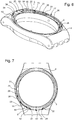
- the figure 6 illustrates a partition 21 of the middle part 2, which thus immobilizes a lug forming lug 4 of the ice 3, after its bayonet mounting in a groove 22 defined parallel to an upper side by this partition 21, and on the other lower side by a lower bearing surface 55 of the middle part 2, and peripherally by a surface 54.
- the partition 21 stops on an end face 23 at the level of the clearance 5. The latter is limited on the opposite side to the groove 22 by a projection 52.
- the top of the partition 21 forms an intermediate bearing surface 28 delimited peripherally by a surface 29, and which is arranged to cooperate with Some parts of the window 3. Beyond, an upper support surface 27 of the middle part 2 is arranged to cooperate with certain parts of a window 7.
- This intermediate support surface 28 is interrupted by a solid portion 26, which also constitutes the bottom of the throat 22.
- the cooperation between at least one lug 4 and a corresponding partition 21 is accompanied by an elastic deformation of at least one of these two constituents, so as to exert a friction ensuring a holding in position, in the absence of particular constraints.
- This cooperation can also include a cooperation between a notch and a notch, or between complementary surfaces similarly, for indexing in the second angular position of maintenance, or / and a brake requiring the application of a higher torque during the disassembly.
- the lug 4 (or / and the corresponding partition 21) is corrugated, or notched, or fluted, or the like.
- the lug 4 comprises at least one end face 41, 42, visible on the figure 9 , in a variant, an angular stop of the ice 3 on the middle part 2, in the bottom 51 of the groove 22.
- the box 1 comprises a rotation stop means 6, which is arranged to angularly secure the middle part 2 and the ice 3 in this second angular position of maintenance.
- this rotation stop means 6 is arranged to allow easy dismantling of the ice 3 relative to the middle part 2.
- the rotation stop means 6 is clipped frontally on the middle part 2 and / or the ice 3 by clipping means that comprises the rotation stop means 6.
- these clipping means are clipping fingers 61, at the distal end of the elastic tabs 70, and which are arranged to cooperate with at least one stop surface complementary, or with complementary clipping fingers, that comprises the middle part 2 and / or the ice 3.
- the clipping fingers 61 cooperate in stop with a second lower surface 32 that includes a second wide peripheral rib 46
- This second lower surface 32 may advantageously comprise a relief complementary to that of the clipping fingers 61; it may also consist of the surface of an elastic element participating in clipping, in addition to the elasticity proper to the tabs 70.
- the rotation stop means 6 is made of plastics material.
- the rotation stop means 6 is a window 7.
- this window 7 is attached to both the middle part 2 and the ice 3.
- the invention is illustrated in a configuration where the ice 3 is, conventionally, an ice covering the main display on an anterior face of the watch, it is understood that the invention is used for the rear face of the watch.
- the component here called “ice 3" can be constituted by a bottom ice, or by an opaque bottom, or other.
- the ice 3 is made of plastic.
- the invention is preferably, but not exclusively, intended for use with plastic uprights, since it has the advantage of avoiding the deformation or even breakage of such layers during the assembly of an ice cream or the like it is also very suitable for electro-formed squares of small section, especially close to 0.5 mm or less than this value, and in particular to 18K gold alloy squares having a section of 0, 5 mm.
- the invention is also advantageous for assembling an ice cream 3 in a material that is also sensitive to shrinkage stresses, such as a plastic ice-cream, or an electroformed bottom, or the like.
- the second angular holding position is delimited by first angular stop means, which comprises the middle part 2, which are arranged to cooperate in abutment abutment with first complementary means of angular stop, that includes the ice 3
- first angular stop means which comprises the middle part 2, which are arranged to cooperate in abutment abutment with first complementary means of angular stop, that includes the ice 3
- the bottom 51 of the groove 22 of the middle 2 constituting these first angular stop means
- a complementary abutment surface 45 that includes the second wide peripheral rib 46 of the lens 3 can also cooperate in abutment with a edge of the solid portion 26 of the caseband 2.
- the rotational stop means 6 advantageously comprises second angular stop means, which are arranged to cooperate in abutment abutment with second complementary middle angular stop means, which comprises the middle part 2, and / or with second complementary means of angular stop ice, which comprises the ice 3.
- the lateral edges 66, 67 of the clipping fingers 61 constitute such second means of angular stop, and are provided to limit the angular deflection of the telescope 7 with respect to the lateral surfaces 24, 25 of the housings 50 of the middle part 2, which constitute these second complementary middle angular stop means.
- These edges 66 and 67 are provided to prevent the pivoting of the ice 3 once the bezel is clipped in position: they constitute stops for the end faces 41, 42, lugs 4.
- the bezel could comprise surfaces separate angular stop, but the realization is simpler with tabs 70 and clipping fingers 61 performing both clipping and holding functions in angular position.
- the edge 68 rests, by its edge 63, on the intermediate bearing surface 28 of the middle part 2, and the edges of this edge 68 can cooperate in abutting abutment with the edges of the solid parts 26, 53 of the middle part 2.
- the telescope 7 may, again, comprise projecting or reentrant parts, with respect to its frustoconical zone 74, which cooperate with a circumferential clearance defined with reentrant portions, respectively protruding, that includes the frustoconical zone 34 of the ice 3.
- the middle part 2 and the window 3 together compress at least one seal, not shown in the figures, housed in a groove 9 that includes the middle part 2 and / or the ice 3.
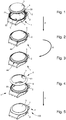
- the Figures 1 to 5 show the kinematics of assembly, that of disassembly being symmetrical.
- the figure 1 shows the presentation of the lugs 4 of the ice 3 facing the notches forming the clearances 5 of the middle part 2.
- the middle 2 comprises, at these partitions, the groove bottom, or the solid part, has end surfaces 23, 25, 51 arranged to abut with complementary abutment surfaces 41, 42, 45 of the 3.
- the relative bayonet cooperation of the middle part 2 and the ice 3 is in one direction, then only an end surface 51 and a complementary abutment surface 42 to ensure the stop in position.
- the figure 4 shows the preferred embodiment, wherein a bezel 7, provided with tabs 70 having clipping fingers 61, is the rotational stop means 6.
- the middle part 2 comprises housing 50, which are arranged to allow the insertion of tabs 70 and clipping fingers 61. As visible on the sections of the figure 15 , these clipping fingers 61 cooperate in clipping support with a return surface 32, which includes the ice 3.
- a frontal force F on the bezel 7 allows the clip on the middle part 2, as visible on the figure 5 .
- the Figures 6 to 8 detail the middle part 2, and its clearances 5, and housing 50, located between projections 52 or solid parts 53 or 26, and laterally bordered by end surfaces 24, 24 for guiding the tabs 70 at the same time. insertion of the telescope 7, and at the bottom by a bottom surface 56 which can be at the same level as the bottom surface 55 of the recesses 5, as in the case of the figures.
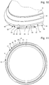
- the Figures 9 to 11 show a mirror 3, with, around the functional central portion for display and closure, a truncated cone portion 34, surrounded by a flange 36, terminated by a lower surface 33 which is flat here.
- the ice 3 has four lugs 4 in the form of flat fins.
- the ice 3 may also comprise plates, or here notches 44, forming a support for a screwing or unscrewing tool, and facilitating the execution by injection of the ice 3 with its lugs 4 or fins.
- This lug 4 projecting radially from the flange 36, is surmounted by a first narrow peripheral rib 40, which has a first lower surface 35, and which is extended by a second wide peripheral rib 46, which has a second lower surface 32 on which The clip 4 of the bezel 7 and the first narrow peripheral rib 40 together define a groove 39.
- the lugs 4, the first narrow peripheral ribs 40, and the second wide peripheral ribs 46 are substantially parallel.
- the figure 10 shows an end face 45 of a second wide peripheral rib 46
- the first narrow peripheral rib 40 bears an impression 43 in the extension of the operating notch 44.
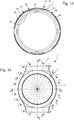
- the Figures 12 to 14 show a bezel 7 equipped with two tabs 70 provided with clipping fingers 61, the edges 66, 67 of these clipping fingers 61 are provided to limit the angular displacement of the bezel 7 with respect to the lateral surfaces 24, 25 of the housings 50 of 2.
- the remainder of the periphery of the bezel 7 has skirts forming curbs 68 interrupted by passages 69, separated from the tabs 70 by narrow passages 65 and wide 69, and having end surfaces forming angular stops.
- the bottom 62 of the passages 65 and 69 form a flat bearing surface.
- the edge 63 of curbs 68 forms another flat bearing surface, parallel to the previous one.
- the tabs 70 comprise, directed towards the center, a substantially cylindrical surface 64.
- the bezel 7 further comprises a frustoconical surface 74, arranged to cooperate with the corresponding frustoconical portion 34 of the ice 3.
- Sections of Figures 15 AA to 15 LL show in detail the cooperation of the different surfaces in the assembled position of the figure 5 .
- the frustoconical surfaces 34 and 74 of the window and the window are provided with a strictly complementary profile.
- the bezel 7 On its larger diameter portion, the bezel 7 is supported on the upper bearing surface 27 of the middle part 2, and thus covers the housing 50 and clipping areas.
- clipping cooperation areas are visible on sections A-A, G-G, H-H.
- the cooperations of the lugs 4 in the grooves 22 are visible on sections E-E, F-F, K-K, L-L.
- the other sections are not all exactly identical, since the borders 68 are interrupted by the passages 65 and 69, and the telescope 7 bears resting, as the case may be, on the surface 27 of the solid section 26, or / and on the intermediate support surface 28, middle 2.
- the bezel 7 bears by its surface 62 on the surface 27 of the solid section 26, while on the left side the edge 63 of the edge 68 of the bezel 7 is further supported on the intermediate bearing surface 28 of the middle part 2.
- the invention also relates to a watch 100 comprising such a box 1.
- the invention makes it possible to have a removable glass and bezel, without resorting to additional components, either to stiffen the middle part or to band the ice.
- This solution generates a cost saving, as well as a saving of space.
Landscapes
- Physics & Mathematics (AREA)
- General Physics & Mathematics (AREA)
- Engineering & Computer Science (AREA)
- Manufacturing & Machinery (AREA)
- Chemical & Material Sciences (AREA)
- Crystallography & Structural Chemistry (AREA)
- Electric Clocks (AREA)
- Mirrors, Picture Frames, Photograph Stands, And Related Fastening Devices (AREA)
- Refrigerator Housings (AREA)
Claims (12)
- Uhrengehäuse (1), umfassend ein aus Kunststoff oder durch Elektroformung gebildetes Mittelteil (2) und ein abnehmbares Glas (3), wobei das Glas (3) oder entsprechend das Mittelteil (2) eine Mehrzahl von gebogenen Vorsprüngen (4) aufweist, die jeweils in einer ersten relativen Winkelposition zwischen dem Mittelteil (2) und dem Glas (3), die erste Einsetz- oder Entnahmeposition genannt wird, von vorn in eine entsprechende Aussparung (5), die das Mittelteil (2) oder entsprechend das Glas (3) aufweist, einsetzbar sind, und wobei jeder Vorsprung (4) dafür ausgelegt ist, in der ersten Einsetz- oder Entnahmewinkelposition eine erste Einsteckposition einzunehmen, wenn der Abstand zwischen dem Mittelteil (2) und dem Glas (3) minimal ist, wobei das Mittelteil (2) und das Glas (3) dafür ausgelegt sind, sich in der ersten Einsteckposition der Vorsprünge (4) relativ zueinander bis in eine zweite Haltewinkelposition zu drehen, in der ein Teil jedes Vorsprungs (4) von vorn hinter einer Halteoberfläche, die eine Halteraste bildet, die das Mittelteil (2) oder entsprechend das Glas (3) aufweist, arretiert wird, wobei das Gehäuse (1) ein Drehblockiermittel (6) aufweist, dadurch gekennzeichnet, dass das Drehblockiermittel- außerhalb des Mittelteils (2) und des Glases (3) angeordnet ist; und- dafür ausgelegt ist, durch Einrasten befestigt zu werden und zu verhindern, dass sich das Glas (3) in Bezug auf das Mittelteil (2) dreht; und- dafür ausgelegt ist, das Mittelteil (2) und das Glas (3) in der zweiten Haltewinkelposition in Winkelrichtung zu befestigen; und- dafür ausgelegt ist, von vorn am Mittelteil (2) und/oder am Glas (3) durch Einrastfinger (61) am distalen Ende von elastischen Klammern (70), die das Drehblockiermittel (6) aufweist, eingerastet zu werden, wobei die Einrastfinger (61) dafür ausgelegt sind, mit mindestens einer komplementären Anschlagoberfläche oder mit komplementären Einrastfingern, die das Mittelteil (2) und/oder das Glas (3) aufweisen, zusammenzuwirken.
- Uhrengehäuse (1) nach Anspruch 1, dadurch gekennzeichnet, dass das Drehblockiermittel (6) dafür ausgelegt ist, von vorn am Mittelteil (2) und am Glas (3) eingerastet zu werden.
- Uhrengehäuse (1) nach Anspruch 1 oder 2, dadurch gekennzeichnet, dass das Drehblockiermittel (6) aus Kunststoff hergestellt ist.
- Uhrengehäuse (1) nach einem der Ansprüche 1 bis 3, dadurch gekennzeichnet, dass das Drehblockiermittel (6) eine Lünette (7) ist, die sowohl an das Mittelteil (2) als auch an das Glas (3) angefügt ist.
- Uhrengehäuse (1) nach einem der Ansprüche 1 bis 4, dadurch gekennzeichnet, dass das Glas (2) ein Bodenglas ist.
- Uhrengehäuse (1) nach einem der Ansprüche 1 bis 4, dadurch gekennzeichnet, dass das Glas (3) ein lichtundurchlässiger Boden ist.
- Uhrengehäuse (1) nach einem der Ansprüche 1 bis 6, dadurch gekennzeichnet, dass das Glas (3) aus Kunststoff hergestellt ist.
- Uhrengehäuse (1) nach einem der Ansprüche 1 bis 7, dadurch gekennzeichnet, dass die zweite Haltewinkelposition begrenzt ist durch erste Winkelblockiermittel, die das Mittelteil (2) aufweist und die dafür ausgelegt sind, sich an ersten komplementären Winkelblockiermitteln, die das Glas (3) aufweist, anschlagend abzustützen.
- Uhrengehäuse (1) nach einem der Ansprüche 1 bis 8, dadurch gekennzeichnet, dass das Drehblockiermittel (6) zwei Winkelblockiermittel (66, 67) aufweist, die dafür ausgelegt sind, mit zweiten komplementären Winkelblockiermitteln (24, 25) des Mittelteils, die das Mittelteil (2) aufweist, und/oder mit zweiten komplementären Winkelblockiermitteln des Glases, die das Glas (3) aufweist, anschlagend abstützend zusammenzuwirken.
- Uhrengehäuse (1) nach Anspruch 9, dadurch gekennzeichnet, dass die Einrastfinger (61) Seitenkanten (66, 67) aufweisen, die zweite Winkelblockiermittel (66, 67) bilden und dafür ausgelegt sind, mit Stirnflächen (41, 42), die die Vorsprünge (4) aufweisen, anschlagend abstützend zusammenzuwirken.
- Uhrengehäuse (1) nach einem der Ansprüche 1 bis 10, dadurch gekennzeichnet, dass in der ersten Einsteckposition dann, wenn der Abstand zwischen dem Mittelteil (2) und dem Glas (3) minimal ist, das Mittelteil (2) und das Glas (3) zusammen mindestens eine Dichtung komprimieren, die in einer Kehle (9) angeordnet ist, die das Mittelteil (2) und/oder das Glas (3) aufweist.
- Uhr (100), umfassend ein Gehäuse (1) nach einem der vorhergehenden Ansprüche.
Priority Applications (5)
| Application Number | Priority Date | Filing Date | Title |
|---|---|---|---|
| EP15156978.7A EP3062171B1 (de) | 2015-02-27 | 2015-02-27 | Armbanduhrgehäuse aus plastik oder galvanoplastisch erzeugtem material mit abnehmbarem uhrenglas |
| US15/014,774 US9618904B2 (en) | 2015-02-27 | 2016-02-03 | Plastic or electroformed watch case with removable crystal |
| JP2016019501A JP6224748B2 (ja) | 2015-02-27 | 2016-02-04 | 取り外し可能な風防を備えたプラスチック製又は電気鋳造された腕時計用ケース |
| CN201620147968.1U CN205594319U (zh) | 2015-02-27 | 2016-02-26 | 手表外壳和包括该手表外壳的手表 |
| CN201610108654.5A CN105929667B (zh) | 2015-02-27 | 2016-02-26 | 带有可移除表镜的塑料或电铸成型的手表外壳 |
Applications Claiming Priority (1)
| Application Number | Priority Date | Filing Date | Title |
|---|---|---|---|
| EP15156978.7A EP3062171B1 (de) | 2015-02-27 | 2015-02-27 | Armbanduhrgehäuse aus plastik oder galvanoplastisch erzeugtem material mit abnehmbarem uhrenglas |
Publications (2)
| Publication Number | Publication Date |
|---|---|
| EP3062171A1 EP3062171A1 (de) | 2016-08-31 |
| EP3062171B1 true EP3062171B1 (de) | 2017-12-13 |
Family
ID=52595151
Family Applications (1)
| Application Number | Title | Priority Date | Filing Date |
|---|---|---|---|
| EP15156978.7A Active EP3062171B1 (de) | 2015-02-27 | 2015-02-27 | Armbanduhrgehäuse aus plastik oder galvanoplastisch erzeugtem material mit abnehmbarem uhrenglas |
Country Status (4)
| Country | Link |
|---|---|
| US (1) | US9618904B2 (de) |
| EP (1) | EP3062171B1 (de) |
| JP (1) | JP6224748B2 (de) |
| CN (2) | CN205594319U (de) |
Families Citing this family (13)
| Publication number | Priority date | Publication date | Assignee | Title |
|---|---|---|---|---|
| EP3062171B1 (de) * | 2015-02-27 | 2017-12-13 | ETA SA Manufacture Horlogère Suisse | Armbanduhrgehäuse aus plastik oder galvanoplastisch erzeugtem material mit abnehmbarem uhrenglas |
| JP1570040S (de) * | 2016-01-28 | 2017-02-20 | ||
| USD886643S1 (en) * | 2017-10-25 | 2020-06-09 | Swatch Ag | Watch case |
| JP6825611B2 (ja) * | 2018-10-03 | 2021-02-03 | カシオ計算機株式会社 | 機器ケース及び時計 |
| USD917310S1 (en) * | 2020-01-31 | 2021-04-27 | Citizen Watch Co., Ltd. | Watch |
| JP7111193B2 (ja) | 2021-01-12 | 2022-08-02 | カシオ計算機株式会社 | 機器ケースの製造方法及び時計の製造方法 |
| CH718341B1 (fr) * | 2021-02-15 | 2023-09-15 | Richemont Int Sa | Boite de montre à lunette amovible. |
| EP4163738B1 (de) * | 2021-10-08 | 2024-03-20 | Louis Lang S.A. | Armbanduhrengehäuse mit einer bajonettverbindung |
| EP4191347B1 (de) | 2021-12-01 | 2025-09-17 | The Swatch Group Research and Development Ltd | Armbanduhrengehäuse mit einem boden, der in einer vordefinierten winkelposition ausgerichtet ist |
| EP4194968A1 (de) * | 2021-12-07 | 2023-06-14 | The Swatch Group Research and Development Ltd | Vorrichtung zur befestigung und ausrichtung eines bodens auf einem gehäuserahmen einer uhr |
| EP4194967B1 (de) * | 2021-12-07 | 2025-05-28 | The Swatch Group Research and Development Ltd | Vorrichtung zur befestigung eines bodens auf einem gehäuserahmen einer uhr |
| EP4513277A1 (de) * | 2023-08-22 | 2025-02-26 | Aima Innovation Sàrl | Halterung für eine abnehmbare uhr |
| EP4645001A1 (de) * | 2024-04-30 | 2025-11-05 | Omega SA | Uhr mit auswechselbarem aussenring |
Family Cites Families (22)
| Publication number | Priority date | Publication date | Assignee | Title |
|---|---|---|---|---|
| CH399335A (fr) * | 1963-09-30 | 1965-04-30 | Gunzinger Freres S A Fabrique | Boîte de montre |
| US3386239A (en) * | 1966-06-16 | 1968-06-04 | Shiffman Jerome | Combination plastic watch case and crystal |
| CH622151B (fr) * | 1977-07-15 | Hans Ulrich Klingenberg | Boite de montre. | |
| CH628771B (fr) | 1978-07-17 | Gen Watch Co Ltd | Boite de montre et montre comportant une telle boite. | |
| US4397567A (en) * | 1980-11-06 | 1983-08-09 | Timex Corporation | Timepiece construction with a caseback removable using a credit card |
| US4627738A (en) * | 1985-01-28 | 1986-12-09 | Kao Chung Fu | Watchcase and watchframe assembly |
| CH666783GA3 (de) * | 1986-12-17 | 1988-08-31 | ||
| US5005161A (en) * | 1990-04-17 | 1991-04-02 | Trans-Action Marketing Corp. | Changeable watch bezel locking mechanism |
| JPH0743251U (ja) * | 1991-12-06 | 1995-08-18 | カシオ計算機株式会社 | 腕時計のベゼル取付構造 |
| CH684297B5 (fr) | 1993-04-20 | 1995-02-28 | Blancpain Sa | Boîte de montre présentant une lunette amovible. |
| US6084504A (en) * | 1998-12-30 | 2000-07-04 | Remind Cap Pte. Ltd. | Timing |
| TW468096B (en) * | 1999-11-04 | 2001-12-11 | Asulab Sa | Case for an instrument of small volume including a manually removable back cover |
| TW468098B (en) * | 1999-11-17 | 2001-12-11 | Rado Montres Sa | Device for assembling a cover made of hard material on the middle part of a watch |
| EP1249741A1 (de) * | 2001-04-12 | 2002-10-16 | Yacht Diamond Watches Ltd. | Mit einem abnehmbaren dekorativen Glasreif ausgerüstetes Uhrengehäuse |
| JP4426899B2 (ja) * | 2004-05-10 | 2010-03-03 | 矢崎総業株式会社 | 部材同士の組付け構造 |
| JP2007171129A (ja) * | 2005-12-26 | 2007-07-05 | Seiko Instruments Inc | 時計 |
| JP5003373B2 (ja) * | 2007-09-14 | 2012-08-15 | セイコーエプソン株式会社 | 時計 |
| US7628068B2 (en) * | 2007-10-24 | 2009-12-08 | Ashcroft, Inc. | Case, window and gasket for measuring device |
| EP2672331B1 (de) * | 2012-06-06 | 2017-11-15 | Omega SA | Uhrgehäuse mit Ausstattung mit verbesserter Fixierung |
| JP6122361B2 (ja) * | 2013-08-12 | 2017-04-26 | セイコーインスツル株式会社 | 携帯機器及び携帯時計 |
| EP3002639B1 (de) * | 2014-10-01 | 2018-01-31 | Montres Breguet SA | Spieluhrlunette mit verbesserter akustischer Leistung |
| EP3062171B1 (de) * | 2015-02-27 | 2017-12-13 | ETA SA Manufacture Horlogère Suisse | Armbanduhrgehäuse aus plastik oder galvanoplastisch erzeugtem material mit abnehmbarem uhrenglas |
-
2015
- 2015-02-27 EP EP15156978.7A patent/EP3062171B1/de active Active
-
2016
- 2016-02-03 US US15/014,774 patent/US9618904B2/en active Active
- 2016-02-04 JP JP2016019501A patent/JP6224748B2/ja active Active
- 2016-02-26 CN CN201620147968.1U patent/CN205594319U/zh not_active Withdrawn - After Issue
- 2016-02-26 CN CN201610108654.5A patent/CN105929667B/zh active Active
Non-Patent Citations (1)
| Title |
|---|
| None * |
Also Published As
| Publication number | Publication date |
|---|---|
| JP2016161566A (ja) | 2016-09-05 |
| US20160252882A1 (en) | 2016-09-01 |
| US9618904B2 (en) | 2017-04-11 |
| CN105929667B (zh) | 2018-06-08 |
| EP3062171A1 (de) | 2016-08-31 |
| JP6224748B2 (ja) | 2017-11-01 |
| CN105929667A (zh) | 2016-09-07 |
| CN205594319U (zh) | 2016-09-21 |
Similar Documents
| Publication | Publication Date | Title |
|---|---|---|
| EP3062171A1 (de) | Armbanduhrgehäuse aus plastik oder galvanoplastisch erzeugtem material mit abnehmbarem uhrenglas | |
| CA2644335C (fr) | Etage de turbine ou de compresseur, en particulier de turbomachine | |
| FR2656391A1 (fr) | Systeme pour l'assemblage coaxial de deux pieces de revolution. | |
| CA2472301C (fr) | Dispositif de fixation par vis et ecrous | |
| FR2528925A1 (fr) | Mecanisme d'embrayage, notamment pour vehicule automobile | |
| FR2735545A1 (fr) | Assemblage de joint universel | |
| EP0359665A1 (de) | Vorrichtung und Verfahren, um einen Wasserzähler auf einem Sockel zu befestigen | |
| EP0722542B1 (de) | Schwimmsattel- scheibenbremse und stift dafür | |
| EP3147525B2 (de) | Reibscheibe, insbesondere für kraftfahrzeug | |
| FR2712951A1 (fr) | Amortisseur d'oscillations de torsion à anneau de friction serré axialement, dans une transmission d'un véhicule automobile. | |
| EP4163738B1 (de) | Armbanduhrengehäuse mit einer bajonettverbindung | |
| CH710789A2 (fr) | Boîte de montre en matière plastique ou électroformée avec glace démontable. | |
| FR3047528A1 (fr) | Dispositif de progressivite pour disque de friction d'embrayage et disque de friction integrant un tel dispositif | |
| EP0237377A1 (de) | Ölabstreifring und Einheit mit in Zylindern gleitenden Kolben sowie ein Verbrennungsmotor mit derartigen Ölabstreifringen | |
| EP2342404B1 (de) | Mechanisches modul für einen fahrzeugschlüssel und herstellungsverfahren dafür | |
| FR3029245A1 (fr) | Piece et systeme d'etancheite pour roulements, et roulement muni de tels pieces et systemes | |
| EP0778427A1 (de) | Drehschwingungsdämpfer,insbesondere für Kraftfahrzeuge | |
| CH716943A2 (fr) | Dispositif de fixation d'un élément d'affichage ou d'habillage d'horlogerie. | |
| EP4323667B1 (de) | Deckel für getriebemotorgruppe für einen elektrischen aktor einer scheibenbremse und getriebemotorgruppe einschliessend eines derartigen deckels | |
| EP4191347B1 (de) | Armbanduhrengehäuse mit einem boden, der in einer vordefinierten winkelposition ausgerichtet ist | |
| FR2602557A1 (fr) | Element d'accouplement destine a absorber un couple dans une colonne de direction de vehicule et colonne de direction de vehicule utilisant un tel accouplement | |
| FR3056460A1 (fr) | Porte de vehicule avec habillage de porte | |
| EP0914567A1 (de) | Scheibe mit reibbelägen für mechanische kupplung | |
| FR2756021A1 (fr) | Motoventilateur a montage d'helice simplifie | |
| EP1649472B1 (de) | Elektromagnetisches ventil, verfahren zum anbringen einer solenoidspule an dem elektromagnetischen ventil und verfahren zum ablösen der solenoidspule von diesem elektromagnetischen ventil |
Legal Events
| Date | Code | Title | Description |
|---|---|---|---|
| PUAI | Public reference made under article 153(3) epc to a published international application that has entered the european phase |
Free format text: ORIGINAL CODE: 0009012 |
|
| AK | Designated contracting states |
Kind code of ref document: A1 Designated state(s): AL AT BE BG CH CY CZ DE DK EE ES FI FR GB GR HR HU IE IS IT LI LT LU LV MC MK MT NL NO PL PT RO RS SE SI SK SM TR |
|
| AX | Request for extension of the european patent |
Extension state: BA ME |
|
| 17P | Request for examination filed |
Effective date: 20170228 |
|
| RBV | Designated contracting states (corrected) |
Designated state(s): AL AT BE BG CH CY CZ DE DK EE ES FI FR GB GR HR HU IE IS IT LI LT LU LV MC MK MT NL NO PL PT RO RS SE SI SK SM TR |
|
| 17Q | First examination report despatched |
Effective date: 20170411 |
|
| GRAP | Despatch of communication of intention to grant a patent |
Free format text: ORIGINAL CODE: EPIDOSNIGR1 |
|
| INTG | Intention to grant announced |
Effective date: 20170802 |
|
| GRAS | Grant fee paid |
Free format text: ORIGINAL CODE: EPIDOSNIGR3 |
|
| GRAA | (expected) grant |
Free format text: ORIGINAL CODE: 0009210 |
|
| REG | Reference to a national code |
Ref country code: GB Ref legal event code: FG4D Free format text: NOT ENGLISH |
|
| REG | Reference to a national code |
Ref country code: AT Ref legal event code: REF Ref document number: 954978 Country of ref document: AT Kind code of ref document: T Effective date: 20171215 Ref country code: CH Ref legal event code: EP Ref country code: CH Ref legal event code: NV Representative=s name: ICB INGENIEURS CONSEILS EN BREVETS SA, CH |
|
| REG | Reference to a national code |
Ref country code: IE Ref legal event code: FG4D Free format text: LANGUAGE OF EP DOCUMENT: FRENCH |
|
| REG | Reference to a national code |
Ref country code: DE Ref legal event code: R096 Ref document number: 602015006556 Country of ref document: DE |
|
| REG | Reference to a national code |
Ref country code: FR Ref legal event code: PLFP Year of fee payment: 4 |
|
| REG | Reference to a national code |
Ref country code: NL Ref legal event code: MP Effective date: 20171213 |
|
| PG25 | Lapsed in a contracting state [announced via postgrant information from national office to epo] |
Ref country code: SE Free format text: LAPSE BECAUSE OF FAILURE TO SUBMIT A TRANSLATION OF THE DESCRIPTION OR TO PAY THE FEE WITHIN THE PRESCRIBED TIME-LIMIT Effective date: 20171213 Ref country code: NO Free format text: LAPSE BECAUSE OF FAILURE TO SUBMIT A TRANSLATION OF THE DESCRIPTION OR TO PAY THE FEE WITHIN THE PRESCRIBED TIME-LIMIT Effective date: 20180313 Ref country code: FI Free format text: LAPSE BECAUSE OF FAILURE TO SUBMIT A TRANSLATION OF THE DESCRIPTION OR TO PAY THE FEE WITHIN THE PRESCRIBED TIME-LIMIT Effective date: 20171213 |
|
| REG | Reference to a national code |
Ref country code: AT Ref legal event code: MK05 Ref document number: 954978 Country of ref document: AT Kind code of ref document: T Effective date: 20171213 |
|
| PG25 | Lapsed in a contracting state [announced via postgrant information from national office to epo] |
Ref country code: RS Free format text: LAPSE BECAUSE OF FAILURE TO SUBMIT A TRANSLATION OF THE DESCRIPTION OR TO PAY THE FEE WITHIN THE PRESCRIBED TIME-LIMIT Effective date: 20171213 Ref country code: HR Free format text: LAPSE BECAUSE OF FAILURE TO SUBMIT A TRANSLATION OF THE DESCRIPTION OR TO PAY THE FEE WITHIN THE PRESCRIBED TIME-LIMIT Effective date: 20171213 Ref country code: BG Free format text: LAPSE BECAUSE OF FAILURE TO SUBMIT A TRANSLATION OF THE DESCRIPTION OR TO PAY THE FEE WITHIN THE PRESCRIBED TIME-LIMIT Effective date: 20180313 Ref country code: GR Free format text: LAPSE BECAUSE OF FAILURE TO SUBMIT A TRANSLATION OF THE DESCRIPTION OR TO PAY THE FEE WITHIN THE PRESCRIBED TIME-LIMIT Effective date: 20180314 Ref country code: LV Free format text: LAPSE BECAUSE OF FAILURE TO SUBMIT A TRANSLATION OF THE DESCRIPTION OR TO PAY THE FEE WITHIN THE PRESCRIBED TIME-LIMIT Effective date: 20171213 |
|
| PG25 | Lapsed in a contracting state [announced via postgrant information from national office to epo] |
Ref country code: NL Free format text: LAPSE BECAUSE OF FAILURE TO SUBMIT A TRANSLATION OF THE DESCRIPTION OR TO PAY THE FEE WITHIN THE PRESCRIBED TIME-LIMIT Effective date: 20171213 |
|
| PG25 | Lapsed in a contracting state [announced via postgrant information from national office to epo] |
Ref country code: EE Free format text: LAPSE BECAUSE OF FAILURE TO SUBMIT A TRANSLATION OF THE DESCRIPTION OR TO PAY THE FEE WITHIN THE PRESCRIBED TIME-LIMIT Effective date: 20171213 Ref country code: SK Free format text: LAPSE BECAUSE OF FAILURE TO SUBMIT A TRANSLATION OF THE DESCRIPTION OR TO PAY THE FEE WITHIN THE PRESCRIBED TIME-LIMIT Effective date: 20171213 Ref country code: CY Free format text: LAPSE BECAUSE OF FAILURE TO SUBMIT A TRANSLATION OF THE DESCRIPTION OR TO PAY THE FEE WITHIN THE PRESCRIBED TIME-LIMIT Effective date: 20171213 Ref country code: CZ Free format text: LAPSE BECAUSE OF FAILURE TO SUBMIT A TRANSLATION OF THE DESCRIPTION OR TO PAY THE FEE WITHIN THE PRESCRIBED TIME-LIMIT Effective date: 20171213 Ref country code: ES Free format text: LAPSE BECAUSE OF FAILURE TO SUBMIT A TRANSLATION OF THE DESCRIPTION OR TO PAY THE FEE WITHIN THE PRESCRIBED TIME-LIMIT Effective date: 20171213 |
|
| PG25 | Lapsed in a contracting state [announced via postgrant information from national office to epo] |
Ref country code: AT Free format text: LAPSE BECAUSE OF FAILURE TO SUBMIT A TRANSLATION OF THE DESCRIPTION OR TO PAY THE FEE WITHIN THE PRESCRIBED TIME-LIMIT Effective date: 20171213 Ref country code: IS Free format text: LAPSE BECAUSE OF FAILURE TO SUBMIT A TRANSLATION OF THE DESCRIPTION OR TO PAY THE FEE WITHIN THE PRESCRIBED TIME-LIMIT Effective date: 20180413 Ref country code: SM Free format text: LAPSE BECAUSE OF FAILURE TO SUBMIT A TRANSLATION OF THE DESCRIPTION OR TO PAY THE FEE WITHIN THE PRESCRIBED TIME-LIMIT Effective date: 20171213 Ref country code: IT Free format text: LAPSE BECAUSE OF FAILURE TO SUBMIT A TRANSLATION OF THE DESCRIPTION OR TO PAY THE FEE WITHIN THE PRESCRIBED TIME-LIMIT Effective date: 20171213 Ref country code: PL Free format text: LAPSE BECAUSE OF FAILURE TO SUBMIT A TRANSLATION OF THE DESCRIPTION OR TO PAY THE FEE WITHIN THE PRESCRIBED TIME-LIMIT Effective date: 20171213 Ref country code: RO Free format text: LAPSE BECAUSE OF FAILURE TO SUBMIT A TRANSLATION OF THE DESCRIPTION OR TO PAY THE FEE WITHIN THE PRESCRIBED TIME-LIMIT Effective date: 20171213 |
|
| REG | Reference to a national code |
Ref country code: DE Ref legal event code: R097 Ref document number: 602015006556 Country of ref document: DE |
|
| PG25 | Lapsed in a contracting state [announced via postgrant information from national office to epo] |
Ref country code: MC Free format text: LAPSE BECAUSE OF FAILURE TO SUBMIT A TRANSLATION OF THE DESCRIPTION OR TO PAY THE FEE WITHIN THE PRESCRIBED TIME-LIMIT Effective date: 20171213 Ref country code: MT Free format text: LAPSE BECAUSE OF FAILURE TO SUBMIT A TRANSLATION OF THE DESCRIPTION OR TO PAY THE FEE WITHIN THE PRESCRIBED TIME-LIMIT Effective date: 20171213 |
|
| PLBE | No opposition filed within time limit |
Free format text: ORIGINAL CODE: 0009261 |
|
| STAA | Information on the status of an ep patent application or granted ep patent |
Free format text: STATUS: NO OPPOSITION FILED WITHIN TIME LIMIT |
|
| 26N | No opposition filed |
Effective date: 20180914 |
|
| REG | Reference to a national code |
Ref country code: IE Ref legal event code: MM4A |
|
| REG | Reference to a national code |
Ref country code: BE Ref legal event code: MM Effective date: 20180228 |
|
| PG25 | Lapsed in a contracting state [announced via postgrant information from national office to epo] |
Ref country code: DK Free format text: LAPSE BECAUSE OF FAILURE TO SUBMIT A TRANSLATION OF THE DESCRIPTION OR TO PAY THE FEE WITHIN THE PRESCRIBED TIME-LIMIT Effective date: 20171213 Ref country code: LU Free format text: LAPSE BECAUSE OF NON-PAYMENT OF DUE FEES Effective date: 20180227 |
|
| PG25 | Lapsed in a contracting state [announced via postgrant information from national office to epo] |
Ref country code: IE Free format text: LAPSE BECAUSE OF NON-PAYMENT OF DUE FEES Effective date: 20180227 |
|
| PG25 | Lapsed in a contracting state [announced via postgrant information from national office to epo] |
Ref country code: BE Free format text: LAPSE BECAUSE OF NON-PAYMENT OF DUE FEES Effective date: 20180228 Ref country code: SI Free format text: LAPSE BECAUSE OF FAILURE TO SUBMIT A TRANSLATION OF THE DESCRIPTION OR TO PAY THE FEE WITHIN THE PRESCRIBED TIME-LIMIT Effective date: 20171213 |
|
| PG25 | Lapsed in a contracting state [announced via postgrant information from national office to epo] |
Ref country code: TR Free format text: LAPSE BECAUSE OF FAILURE TO SUBMIT A TRANSLATION OF THE DESCRIPTION OR TO PAY THE FEE WITHIN THE PRESCRIBED TIME-LIMIT Effective date: 20171213 |
|
| PG25 | Lapsed in a contracting state [announced via postgrant information from national office to epo] |
Ref country code: PT Free format text: LAPSE BECAUSE OF FAILURE TO SUBMIT A TRANSLATION OF THE DESCRIPTION OR TO PAY THE FEE WITHIN THE PRESCRIBED TIME-LIMIT Effective date: 20171213 |
|
| PG25 | Lapsed in a contracting state [announced via postgrant information from national office to epo] |
Ref country code: HU Free format text: LAPSE BECAUSE OF FAILURE TO SUBMIT A TRANSLATION OF THE DESCRIPTION OR TO PAY THE FEE WITHIN THE PRESCRIBED TIME-LIMIT; INVALID AB INITIO Effective date: 20150227 Ref country code: MK Free format text: LAPSE BECAUSE OF NON-PAYMENT OF DUE FEES Effective date: 20171213 Ref country code: LT Free format text: LAPSE BECAUSE OF FAILURE TO SUBMIT A TRANSLATION OF THE DESCRIPTION OR TO PAY THE FEE WITHIN THE PRESCRIBED TIME-LIMIT Effective date: 20171213 |
|
| PG25 | Lapsed in a contracting state [announced via postgrant information from national office to epo] |
Ref country code: AL Free format text: LAPSE BECAUSE OF FAILURE TO SUBMIT A TRANSLATION OF THE DESCRIPTION OR TO PAY THE FEE WITHIN THE PRESCRIBED TIME-LIMIT Effective date: 20171213 |
|
| P01 | Opt-out of the competence of the unified patent court (upc) registered |
Effective date: 20230701 |
|
| REG | Reference to a national code |
Ref country code: CH Ref legal event code: U11 Free format text: ST27 STATUS EVENT CODE: U-0-0-U10-U11 (AS PROVIDED BY THE NATIONAL OFFICE) Effective date: 20260301 |
|
| PGFP | Annual fee paid to national office [announced via postgrant information from national office to epo] |
Ref country code: GB Payment date: 20260121 Year of fee payment: 12 |
|
| PGFP | Annual fee paid to national office [announced via postgrant information from national office to epo] |
Ref country code: DE Payment date: 20260121 Year of fee payment: 12 |
|
| PGFP | Annual fee paid to national office [announced via postgrant information from national office to epo] |
Ref country code: FR Payment date: 20260121 Year of fee payment: 12 |
|
| PGFP | Annual fee paid to national office [announced via postgrant information from national office to epo] |
Ref country code: CH Payment date: 20260301 Year of fee payment: 12 |