EP3063261B1 - Couvercle pour conteneur de culture cellulaire - Google Patents
Couvercle pour conteneur de culture cellulaire Download PDFInfo
- Publication number
- EP3063261B1 EP3063261B1 EP14799361.2A EP14799361A EP3063261B1 EP 3063261 B1 EP3063261 B1 EP 3063261B1 EP 14799361 A EP14799361 A EP 14799361A EP 3063261 B1 EP3063261 B1 EP 3063261B1
- Authority
- EP
- European Patent Office
- Prior art keywords
- cover
- valve arrangement
- valve
- cell culture
- culture container
- Prior art date
- Legal status (The legal status is an assumption and is not a legal conclusion. Google has not performed a legal analysis and makes no representation as to the accuracy of the status listed.)
- Active
Links
Images



Classifications
-
- C—CHEMISTRY; METALLURGY
- C12—BIOCHEMISTRY; BEER; SPIRITS; WINE; VINEGAR; MICROBIOLOGY; ENZYMOLOGY; MUTATION OR GENETIC ENGINEERING
- C12M—APPARATUS FOR ENZYMOLOGY OR MICROBIOLOGY; APPARATUS FOR CULTURING MICROORGANISMS FOR PRODUCING BIOMASS, FOR GROWING CELLS OR FOR OBTAINING FERMENTATION OR METABOLIC PRODUCTS, i.e. BIOREACTORS OR FERMENTERS
- C12M23/00—Constructional details, e.g. recesses, hinges
- C12M23/38—Caps; Covers; Plugs; Pouring means
-
- C—CHEMISTRY; METALLURGY
- C12—BIOCHEMISTRY; BEER; SPIRITS; WINE; VINEGAR; MICROBIOLOGY; ENZYMOLOGY; MUTATION OR GENETIC ENGINEERING
- C12M—APPARATUS FOR ENZYMOLOGY OR MICROBIOLOGY; APPARATUS FOR CULTURING MICROORGANISMS FOR PRODUCING BIOMASS, FOR GROWING CELLS OR FOR OBTAINING FERMENTATION OR METABOLIC PRODUCTS, i.e. BIOREACTORS OR FERMENTERS
- C12M23/00—Constructional details, e.g. recesses, hinges
- C12M23/40—Manifolds; Distribution pieces
-
- C—CHEMISTRY; METALLURGY
- C12—BIOCHEMISTRY; BEER; SPIRITS; WINE; VINEGAR; MICROBIOLOGY; ENZYMOLOGY; MUTATION OR GENETIC ENGINEERING
- C12M—APPARATUS FOR ENZYMOLOGY OR MICROBIOLOGY; APPARATUS FOR CULTURING MICROORGANISMS FOR PRODUCING BIOMASS, FOR GROWING CELLS OR FOR OBTAINING FERMENTATION OR METABOLIC PRODUCTS, i.e. BIOREACTORS OR FERMENTERS
- C12M29/00—Means for introduction, extraction or recirculation of materials, e.g. pumps
-
- C—CHEMISTRY; METALLURGY
- C12—BIOCHEMISTRY; BEER; SPIRITS; WINE; VINEGAR; MICROBIOLOGY; ENZYMOLOGY; MUTATION OR GENETIC ENGINEERING
- C12M—APPARATUS FOR ENZYMOLOGY OR MICROBIOLOGY; APPARATUS FOR CULTURING MICROORGANISMS FOR PRODUCING BIOMASS, FOR GROWING CELLS OR FOR OBTAINING FERMENTATION OR METABOLIC PRODUCTS, i.e. BIOREACTORS OR FERMENTERS
- C12M37/00—Means for sterilizing, maintaining sterile conditions or avoiding chemical or biological contamination
-
- C—CHEMISTRY; METALLURGY
- C12—BIOCHEMISTRY; BEER; SPIRITS; WINE; VINEGAR; MICROBIOLOGY; ENZYMOLOGY; MUTATION OR GENETIC ENGINEERING
- C12M—APPARATUS FOR ENZYMOLOGY OR MICROBIOLOGY; APPARATUS FOR CULTURING MICROORGANISMS FOR PRODUCING BIOMASS, FOR GROWING CELLS OR FOR OBTAINING FERMENTATION OR METABOLIC PRODUCTS, i.e. BIOREACTORS OR FERMENTERS
- C12M41/00—Means for regulation, monitoring, measurement or control, e.g. flow regulation
-
- C—CHEMISTRY; METALLURGY
- C12—BIOCHEMISTRY; BEER; SPIRITS; WINE; VINEGAR; MICROBIOLOGY; ENZYMOLOGY; MUTATION OR GENETIC ENGINEERING
- C12M—APPARATUS FOR ENZYMOLOGY OR MICROBIOLOGY; APPARATUS FOR CULTURING MICROORGANISMS FOR PRODUCING BIOMASS, FOR GROWING CELLS OR FOR OBTAINING FERMENTATION OR METABOLIC PRODUCTS, i.e. BIOREACTORS OR FERMENTERS
- C12M41/00—Means for regulation, monitoring, measurement or control, e.g. flow regulation
- C12M41/40—Means for regulation, monitoring, measurement or control, e.g. flow regulation of pressure
Definitions
- the present invention relates to a cover for cell culture containers, such as are commonly used for the industrial cultivation of adherent cells in laboratories in the pharmaceutical and biotechnology industries.
- Cell culture containers are known in the field of cell culture, which are generally made of transparent plastic, are often disposable or single-use containers and have one or more screw caps.
- the cell culture containers are used to multiply or cultivate cells and to observe the growth. To do this, the cells to be cultivated are placed in the container (often in the form of a bottle) together with a suitable nutrient medium, where they can multiply under the appropriate environmental conditions.
- the interior of the cell culture vessel comprises a volume, which is therefore referred to as the culture volume.
- the ambient conditions are usually an ambient temperature of 37°C with a CO 2 content of 5% and a relative humidity (rH) of 95%.
- the cells either have to be harvested for further use or divided into several new cell culture containers. In some cases it is also necessary to exchange the culture medium during cultivation (cell maintenance).
- the term fluid is used herein to summarize the exchange of nutrient medium and/or the removal of adherent cells, optionally with or without nutrient medium.
- the above-mentioned process steps in the cell culture are carried out manually with the aid of hand pipettes under a sterile hood by appropriately trained technical assistants. i.e. the lids of the cell culture containers are unscrewed by hand and then closed again manually after filling or removal. Shaking machines and other laboratory equipment specially designed for this purpose are already replacing sub-processes so that all activities do not have to be carried out manually.
- the cell culture containers currently in use have screw caps or closures, which are optionally designed with or without a ventilation membrane to ensure a targeted CO 2 exchange with the cells inside the bottle.
- An important aspect of these ventilation or filter membranes is that the pore size of the membrane does not exceed 0.22 ⁇ m so that the membrane can still be considered a sterile membrane.
- cell culture containers with pierceable membranes which are designed, for example, as hydrophobic filter membranes, such as e.g. B. the "AutoFlask” cell culture flask offered by Greiner Bio-One.
- Cell culture containers of this type are optimized for automated processes, are compatible with a variety of cell culture and liquid handling systems and have, for example, a physical surface treatment for adherent cells.
- a disadvantage of such products is that the user is limited precisely to the design, the size and the surface properties. For this reason, such systems have hitherto only been used to a limited extent.
- the German patent application DE 10 2013 201 069 The applicant is directed to a cell culture system with a fluid supply interface and a cell culture container specially designed for this purpose, with the cell culture container having a filling and/or ventilation opening and at least one counter-coupling formation which is separate from the filling and/or ventilation opening and which is used for the production and is designed to release a coupling engagement with a corresponding coupling formation of the fluid supply interface.
- This cell culture system or this cell culture container is also specially adapted to the corresponding system or interface, which is why the standard cell culture containers used up to now can only be used in part or to a very limited extent. To a whole laboratory or a production with such Equipping new types of cell culture containers therefore requires very high investments.
- the U.S. 2011/223076 A1 discloses a fitting for a bioreactor vessel.
- the fitting includes a plurality of ports suitable for insertion of sensors or probes and for delivery of a sample, and a valve assembly for a cleaning port.
- the DE 42 07 346 A1 discloses a control device for a valve of a rotary filler for the beverage industry, which has a valve with a valve tappet mounted movably in a valve housing between an open and a closed position and a tappet magnet arranged in this. Furthermore, there is at least one control magnet arranged outside of the valve housing, which, when the rotary filler rotates, passes through a contact position that interacts with the tappet magnet.
- At least part of the valve housing is made of a magnetizable material, to which the plunger magnet adheres after passing through the contact point, and a reverse-magnetically polarized separating magnet is arranged downstream of the control magnet, which separates the plunger magnet solves, whereby the valve tappet can be arranged in a bistable manner.
- US5848622 discloses a closure for a bioreactor vessel, consisting of a cover (20) with a distribution element (24) and a valve element (28).
- the valve element (24) has the function that the bioreactor vessel is vented when the lid is opened manually.
- the object of the present invention to provide a technical teaching for a lid of a cell culture container, the lid not only overcoming the disadvantages described above, but also being able to be used with standard cell culture containers used to date, being inexpensive to produce and simple structure.
- a cover for a cell culture container which encloses a culture volume and has an opening with a valve arrangement, suitable for filling the cell culture container with a fluid and/or for pumping fluid out of the cell culture container, and an equalization opening for aerating the cell culture container and/or is suitable for pressure equalization during filling or pumping out, wherein the valve arrangement can be switched magnetically between an open position and a closed position and can be connected to a fluid supply interface and can be switched in a non-contact manner with magnetic elements.
- existing cell culture containers can easily be used in an automated cell culture system. Converting from manual processing to an essentially automated cell culture system only requires investing in new lids for existing cell culture vessels.
- the compensating opening integrated in the lid or closure eliminates the need for an additional opening in the cell culture container. A proper CO 2 exchange is thus guaranteed. This also ensures a sufficient volume flow when filling or emptying the cell culture container.
- the structure of the lid is simple and its production is inexpensive, in particular in comparison to the special production of an entire cell culture container for an automated cell culture system.
- Automated cell culture systems or installations with a cell culture container equipped with the lid according to the invention can be used in a simple manner by the valve arrangement, which is designed to be switchable without contact.
- the ability to switch without contact allows for a simple structure and particularly simple handling, since no cables or other connections have to be connected to the cover in order to open or close the valve arrangement.
- this makes it possible to clean an automated cell culture system in a simple manner, in contrast to switching mechanisms of valve arrangements, which can only be opened or closed by touch and can only be cleaned with great effort due to the complex structure.
- the equalization opening is designed either as an opening and/or as a membrane. The equalization opening can thus be opened or closed during the filling or emptying process, depending on whether the volume flow is to be increased or decreased.
- the design as a membrane is important for the CO 2 exchange in the resting state, ie when there is no removal, filling or pumping out.
- the compensating opening such as a membrane of this type, can also be protected from damage, for example by a grid, without having to accept any impairments in its function. If the cover has a substantially cylindrical shape, the Compensation opening may be arranged on the lateral surface or on the end face of the lid.
- valve arrangement and the opening of the cell culture container are particularly preferably arranged coaxially. This means that when the cover is cylindrical, the valve arrangement is arranged essentially in the middle of the end face of the cover, i.e. in the extension of the common axis. In this arrangement, the compensation opening is advantageously arranged on the lateral surface.
- the compensation opening is designed in such a way that it is closed when the valve arrangement is not connected to the fluid supply interface and is open when the valve arrangement is connected to the fluid supply interface.
- this is done by means of a mechanical sliding mechanism that has a return spring.
- the cover can be releasably connected to the opening of the cell culture container by means of a threaded connection, a bayonet connection, a press-fit connection, a snap or plug-in connection or a combination thereof.
- the connection by means of a thread i.e. the classic screw cap, will be the main connection option used because the cell culture containers used to date have an opening with a screw thread. It is noted at this point that the corresponding connection can also be provided with seals.
- the valve arrangement particularly advantageously comprises a magnetic ball valve, a magnetic element being arranged on the side of the valve arrangement near the container and a ball made of magnetic material being arranged on the side of the valve arrangement remote from the container.
- the magnetic ball valve has the advantage that it takes up hardly any space, is simple in design and the side of the lid with the ball that is far from the container can be cleaned relatively easily. This means that one of the essential requirements of an automatic cell culture system is met, namely contamination of the cell cultures as far as possible to reduce.
- the ball valve is controlled by the control unit within the fluid supply interface.
- the magnetic forces of the ball and the magnetic element act on the valve seat in such a way that the corresponding elements attract each other and the ball thus sits relatively firmly on the valve seat, preventing fluid from flowing into or out of the cell culture container.
- the magnetic elements controlled by the control unit of the fluid supply interface are arranged in the vicinity of the ball and dimensioned such that activation of the magnetic elements generates a magnetic field that moves the ball out of its closed position and thus the flow path is released for the fluid.
- the valve seat is preferably conical or hemispherical.
- the ball in the closed state, the ball is effectively held on the valve seat and can only be moved away from there with a corresponding minimal force.
- the valve seat it is also possible for the valve seat to be of flat design. Cleaning is then possible in a particularly effective manner since the intermediate spaces are more accessible for the cleaning liquid.
- the valve seat comprises a thermoplastic material such as TPE, silicone or the like, with the thermoplastic material preferably having a Shore A hardness of about 25 to about 50. Materials of this type give the valve seat an essentially easily deformable property and thus lead to an improved sealing effect of the valve arrangement. It is also possible that the valve seat is made from different materials by two-component injection molding.
- the cover is preferably produced in one piece from plastic by means of injection molding, and the valve arrangement can be pressed onto it with a press fit.
- injection molding is a proven, technically mature and very inexpensive manufacturing variant. A simple construction is provided by simply plugging on the valve arrangement.
- individual components of the valve arrangement can also be made of plastic using the injection molding process, including injection molding with two or more components. These can be easily assembled with the other components and the cover elements to form the cover according to the invention. That's it It is also possible to design the lid as a one-time/disposable item in order to avoid the expense of reprocessing after use.
- the cover has a further valve arrangement as a compensating opening.
- another valve arrangement can take over its function.
- a siphon for example, can be used to separate the valve assemblies.
- valve arrangements in the cover, preferably next to one another.
- the requirements for cleanliness and the avoidance of contamination can be met even more, e.g. by using one valve arrangement only for the introduction and another valve arrangement only for the pumping out or discharge.
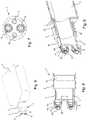
- FIG. 1 shows a perspective view of a preferred first embodiment of a lid 1 according to the invention, which has a substantially cylindrical lid housing 3 as the lateral surface, a connection piece 5 remote from the container, on the outer surface of which there is a compensation opening 7, and a valve arrangement 9 arranged at the other end of the connection piece 5.
- the valve assembly 9 includes a magnetic ball valve, which is explained in more detail with reference to the following figures.
- the compensating opening 7 is at least partially covered with a cover 11 which has a plurality of openings 13 and protects a membrane which may be underneath.
- the compensating opening 7 is arranged essentially on the peripheral or lateral surface of the connection piece 5 .
- the diameter of the cover housing 3 is dimensioned such that the connecting piece 5 and the valve arrangement 9 do not protrude beyond the outer surface in the radial direction.
- FIG. 12 shows a cross-sectional view of the embodiment of the lid 1 according to the invention 1 .
- the interior of the lid housing 3 is not shown threaded to mate with a corresponding threaded port stud or neck of a cell culture vessel.
- cover-container connections can also be used, such as bayonet lock connections, press-fit connections, plug-in connections or the like.
- the equalization opening 7 is equipped with a hydrophobic membrane 15, which enables an exchange of CO 2 (or other gases) between the interior of the cell culture container and the outside environment, in particular during storage of the cell culture container.
- the valve arrangement 9 comprises a socket or extension 19 at the end close to the container, which is connected to the connecting piece 5, and a valve housing 17 arranged at the end of the socket 19 remote from the container.
- a magnetic element 21 is arranged inside the valve housing 17 and at the end of the valve housing remote from the container
- a valve seat 25 is arranged at 17, which has a conical shape that tapers inwards, so that a magnetic ball 23 is arranged on the valve seat 25 from the outside.
- the valve seat 25 is formed from a thermoplastic plastics material. Examples of such a material are the thermoplastic elastomers (TPE) available under the trade name Mediprene 500300M from Elasto or under the trade name Thermolast M TM4RST from Kraiburg TPE. It goes without saying that the person skilled in the art can optionally also use similar plastic materials or composite materials with similar physical properties.
- the magnetic element 21 is designed as a permanent magnet, with ferromagnetic materials also being suitable.
- the ball 23 is also made of magnetic material, i.e. as a permanent magnet or as a ferromagnet, and it has a magnetic orientation which is opposite to the magnetic polarity of the magnetic element 21, in such a way that in the normal state, i.e. in the state in which the cover 1 is screwed or placed onto a cell culture container, the ball 23 and the magnetic element 21 attract each other and block the valve opening in the valve seat 25 sufficiently so that no fluid can get out of or into the cell culture container.
- all elements of the valve assembly 9, with the exception of the magnetically designed components, the magnetic element 21 and the ball 23, can be formed integrally with the other sections of the cover, e.g. embodied by a single injection molded component into which the magnetic element 21 are arranged from the inside and the ball 23 from the outside.
- a type of bellows element is arranged between the connecting piece 5 and the cover housing 3, which offers a certain degree of flexibility for the elements arranged on the connecting piece 5 in relation to the cover housing 3, but fluid-tightness between the connecting piece 5 and cover housing 3 is ensured at all times.
- the bellows element is not affected by the fact that the cover housing 3 is one piece with the connection piece 5 .
- FIG 3 shows a cross-sectional view of with reference to FIG Figures 1 and 2 described preferred embodiment of the lid according to the invention.
- a description of the elements is omitted at this point and the detailed description is referred to 2 referred.
- FIG. 4 shows a perspective representation of a further embodiment of the cover according to the invention.
- the compensating opening 7 is essentially integrated into the lateral surface of the cylindrical connecting piece 5 in that the openings 13 extend slit-like in the circumferential direction parallel to one another over a predetermined angular range of the circumference of the connecting piece 5 .
- the membrane 15 is arranged, for example, on the inner surface of the connection piece 5 in such a way that it covers the openings 13 from the inside.
- a cover 11 as in the first embodiment is the one in this embodiment 4 unavailable. All other elements of this second embodiment are the same as those with reference to FIG Figures 1 to 3 described elements of the first embodiment are identical.
- figure 5 shows a perspective representation of a lid according to the invention according to the first embodiment, which is screwed onto a cell culture container and docked at a fluid connection interface of a cell culture system.
- the cover 1 is fastened in a known manner inside its cover housing 3 by means of a thread on a corresponding threaded connector of an opening of the cell culture container.
- the valve assembly is 9 (in figure 5 not visible) docked to a corresponding connection formation of a fluid supply interface 6 of a cell culture system.
- the fluid supply interface 6 has four connection formations 8 to which corresponding supply containers for storing fluids or for receiving fluids in the operating state of the cell culture system are connected.
- connection formations 8 to which corresponding supply containers for storing fluids or for receiving fluids in the operating state of the cell culture system are connected.
- the control unit and the corresponding signaling means to control the valve arrangement 9 without contact, i.e. in particular to move the magnetic ball away from the valve seat of the valve arrangement 9 in such a way that a fluid flow path is made possible depending on the wiring or control of the fluid supply interface 6.
- the docking principle and the control within the fluid supply interface is described below with reference to the Figures 10 and 11 described in more detail.
- FIG. 6 shows a perspective view of a cell culture container with a lid according to a further embodiment of the present invention, in which a commercially available cell culture container 4 is equipped with a lid 1 according to the invention, which has not just one but two valve assemblies 9 as a significant difference from the previously described embodiments .
- the two valve arrangements 9 are arranged parallel to one another in the axial direction on the essentially cylindrical connection piece 5 , namely on the side of the lid 1 remote from the container.
- the valve arrangements 9 are of essentially identical design and are arranged essentially symmetrically with respect to the center point of the end face of the connection piece 5, which is circular in this case.
- FIG 7 is a front view of the lid 1 according to FIG 6 illustrated second embodiment. It can be seen that the end face of the connecting piece 5 has, in addition to the two valve arrangements 9, two indentations 10 which are suitable for automatically screwing on or unscrewing the cover 1 and/or for centering and thus aligning the cover 1 with respect to the cell culture container 4.
- the depressions are 10 also suitable for aligning the cover 1 with respect to the fluid supply interface 6. It should be noted at this point that the indentations 10 are not holes in the end face of the connection piece 5, but merely recesses with a sufficient depth to ensure the function described above.
- indentations 10 do not have to be arranged in the end face; there can also be more or only one depression 10 .
- shape of the recess 10 does not necessarily have to be circular. It can be rectangular, square, star-shaped, polygonal or of any other shape.
- FIG. 8 shows a cross-sectional view of a lid according to the in the Figures 6 and 7 illustrated further embodiment of the present invention.
- the cover 1 has two valve arrangements 9 in the axial direction, which are aligned parallel to one another and are of essentially identical design. Its elements are identical to those described in relation to the first preferred embodiment. For this reason, it will not be repeated here.
- valve arrangements 9 instead of one fluid flow path, two possible fluid flow paths can form when the cover 1 is docked, depending on whether the corresponding valve arrangements 9 are open or not. It is understood that the control of the two valve assemblies 9 from the 8 illustrated embodiment can be done independently. In particular, it is also possible that when one of the valve arrangements 9 is open and a fluid flows through, the other valve arrangement can be used as a pressure compensation opening in order to control the volume flow or its filling/emptying rate.
- the compensating opening 7 is provided by the membrane 15 which is arranged on the peripheral surface of the connecting piece 5 .
- the lid housing 3 is provided with a threaded section 12 in its interior which matches a corresponding threaded section on the threaded socket of the cell culture container.
- the radial expansion of the connection piece 5 provided with the two valve arrangements 9 does not protrude beyond the cover housing 3 .
- FIG. 9 shows a detail of a perspective cross-sectional view of the in 6 shown cover with connected cell culture container.
- the cover housing 3 of the cover 1 has a threaded section 12 on its inside, which fits together with a corresponding threaded section on the threaded socket 14 of the cell culture container 4 .
- the completely screwed-on state of the cover 1 is shown, whereby it can be seen that the open end of the threaded connector 14 of the cell culture container 4 abuts the stepped stop between the housing cover 3 and the connection piece 5 .
- the cover 1 is thus firmly screwed onto the cell culture container 4, with the stop described above providing additional stabilization of the connection.
- the lid according to the invention can also be used on cell culture containers which have more than one opening for attaching a lid.
- the main advantage of the present invention lies in equipping existing cell culture containers with a corresponding interface so that the existing cell culture containers can be connected to an automated cell culture system.
- the cover according to the invention in particular the valve arrangement, can include a device that prevents elements of the valve arrangement, such as the magnetic ball in the case of a magnetic ball valve, from getting lost, especially in the non-docked state.
- This can be a type of attachable or detachable (lattice) cage, preferably made of plastic, which is placed on the cover around the valve arrangement(s). It is conceivable that this cage automatically pivots to the side when the cover is docked onto the fluid supply interface or can also be removed by hand.
- valve arrangement 9 is shown on the right side of the inventive cover 1 according to the first embodiment shown here; the fluid supply interface 6 into which the valve arrangement 9 of the cover 1 is inserted can be seen on the left-hand side.
- the valve arrangement 9 is pushed into the empty space 18 , specifically in the center in such a way that the magnetic ball 23 of the valve arrangement 9 can still move essentially freely on the valve seat 25 .
- the valve arrangement 9 engages with the fluid supply interface 6 via the end ring surface of the valve seat 25 with a counter-sealing surface 20 of the fluid supply interface 6 . This fluid-tight contact of the end ring surface with the counter-sealing surface 20 ensures that no fluid can get outside the fluid flow path.
- the valve arrangement 9 is open, i.e.
- the control arrangement 24 comprises a switching arrangement 32 and a roller 28.
- the rotatable roller 28 has a (in 11 not shown) electromotive drive for rotation about the roll axis and a plurality of magnetic elements 30, which are designed as permanent magnets in the illustrated embodiment.
- the magnetic elements 30 are preferably oriented such that their NS polarization direction coincides with a radial direction extending from the roll axis. At the axial positions of the in 11 magnetic elements 30 shown, further magnetic elements 30 can be arranged along the circumference of the roller 28 .
- a switching arrangement 32 is provided between the fluid supply interface 6 and the roller 28 in order to enable precise switching of the valve arrangements docked at the fluid supply interface 6 .
- exactly one magnetic element 26 is provided on the switching arrangement 32, which is designed here as a permanent magnet.
- Each magnetic element 26 is arranged in a channel, the magnetic element 26 between a roll-near and is displaceably mounted in a position remote from the roller or closer to the valve arrangement.
- the magnetic elements 26 are selected in such a way that the magnetic field emanating from them and acting on the balls 23 of the corresponding valve arrangement 9 is stronger, at least in the position away from the roller, than the magnetic field emanating from the magnetic elements 21 on the valve seat 25 and acting on the ball 23. Furthermore, the magnetic elements 26 are preferably arranged polarized along their displacement axis, for example in such a way that a pole such as the north pole points to the associated valve arrangement and the respective opposite pole, i.e. the south pole, points to the roller 28 .
- the switching arrangement 32 is preferably arranged in such a way that the magnetic elements 26 in the channels are prestressed by gravity into their position closer to the rollers, in which, for example, the two 11 magnetic elements arranged on the right.
- the magnetic elements 26 can be shifted from their position closer to the roller to their position further away from the roller or closer to the valve arrangement by the magnetic fields emanating from the magnetic elements 30, for example by lying opposite one another of poles of the same orientation, i.e. of poles that repel each other.
- the magnetic elements 30 and the magnetic elements 26 will attract each other and thus exert an attractive force in addition to the force of gravity.
- electromagnets can also be used as actuators in order to cause the valves to open and close.
- piezoelectric valves can also be used or other valves known to the person skilled in the art, which are easy to clean, especially on the side remote from the container, in order to avoid contamination in the automated cell culture system as far as possible .
- a cover for a cell culture container which can be used with standard cell culture containers used to date, is inexpensive to produce and has a simple structure.
Landscapes
- Health & Medical Sciences (AREA)
- Chemical & Material Sciences (AREA)
- Life Sciences & Earth Sciences (AREA)
- Organic Chemistry (AREA)
- Wood Science & Technology (AREA)
- Engineering & Computer Science (AREA)
- Bioinformatics & Cheminformatics (AREA)
- Zoology (AREA)
- General Engineering & Computer Science (AREA)
- Sustainable Development (AREA)
- Microbiology (AREA)
- Biochemistry (AREA)
- Biomedical Technology (AREA)
- General Health & Medical Sciences (AREA)
- Genetics & Genomics (AREA)
- Biotechnology (AREA)
- Clinical Laboratory Science (AREA)
- Analytical Chemistry (AREA)
- Molecular Biology (AREA)
- Apparatus Associated With Microorganisms And Enzymes (AREA)
Claims (13)
- Couvercle (1) pour un contenant de culture cellulaire (4), qui renferme un volume de culture et présente un orifice, avecun ensemble formant soupape (9) adapté pour remplir le contenant de culture cellulaire (4) d'un fluide et/ou pour évacuer par pompage du fluide hors du contenant de culture cellulaire (4),caractérisé en ce queil présente un orifice de compensation (7) qui est adapté pour l'aération du contenant de culture cellulaire (4) et/ou pour la compensation de pression au cours du remplissage ou de l'évacuation par pompage, dans lequel l'ensemble formant soupape (9) peut être commuté magnétiquement entre une position de passage et une position de blocage et peut être raccordé à une interface d'alimentation en fluide (6) et est réalisé avec des éléments magnétiques de manière commutable sans contact.
- Couvercle (1) selon la revendication 1, caractérisé en ce que l'orifice de compensation (7) est réalisé au choix comme pouvant être ouvert et/ou comme une membrane (15).
- Couvercle (1) selon l'une quelconque des revendications précédentes, caractérisé en ce que l'ensemble formant soupape (9) et l'orifice du contenant de culture cellulaire (4) sont disposés de manière coaxiale.
- Couvercle (1) selon l'une quelconque des revendications précédentes, caractérisé en ce que l'orifice de compensation (7) est configuré de telle manière qu'il est fermé lorsque l'ensemble formant soupape (9) n'est pas raccordé à l'interface d'alimentation en fluide (6) et est ouvert lorsque l'ensemble formant soupape (9) est raccordé à l'interface d'alimentation en fluide (6).
- Couvercle (1) selon l'une quelconque des revendications précédentes, caractérisé en ce que le couvercle (1) peut être relié de manière amovible à l'orifice du contenant de culture cellulaire (4) au moyen d'une liaison par filetage, d'une liaison par fermeture à baïonnette, d'une liaison par ajustement serré, d'une liaison par déclic ou par enfichage ou d'une combinaison de celles-ci.
- Couvercle (1) selon l'une quelconque des revendications précédentes, caractérisé en ce que l'ensemble formant soupape (9) comprend une soupape sphérique magnétique, dans lequel un élément magnétique (21) est disposé sur le côté à proximité du contenant de l'ensemble formant soupape (9) sur le siège de soupape (25) et une sphère (23) composée d'un matériau magnétique est disposée sur le côté éloigné du contenant de l'ensemble formant soupape (9).
- Couvercle (1) selon la revendication 6, caractérisé en ce que le siège de soupape (25) présente un matériau synthétique thermoplastique tel que le TPE, le silicone ou similaire.
- Couvercle (1) selon la revendication 7, caractérisé en ce que le matériau synthétique thermoplastique présente une durée Shore A d'environ 25 à environ 50.
- Couvercle (1) selon l'une quelconque des revendications 6 à 8, caractérisé en ce que le siège de soupape (25) est réalisé de manière conique ou en forme de demi-sphère.
- Couvercle (1) selon l'une quelconque des revendications précédentes, caractérisé en ce qu'il est fabriqué, à l'exception de l'ensemble formant soupape (9), d'un seul tenant à partir de matière synthétique au moyen d'un moulage par injection, et que l'ensemble formant soupape (9) peut être emboîté sur celui-ci avec un ajustement serré.
- Couvercle (1) selon la revendication 10, caractérisé en ce qu'il est réalisé en tant qu'article à usage unique/jetable.
- Couvercle (1) selon l'une quelconque des revendications précédentes, caractérisé en ce qu'il présente en tant qu'orifice de compensation (7) un autre ensemble formant soupape (9).
- Contenant de culture cellulaire (4), qui renferme un volume de culture et présente un orifice, avec un couvercle (1) selon l'une quelconque des revendications précédentes.
Applications Claiming Priority (2)
| Application Number | Priority Date | Filing Date | Title |
|---|---|---|---|
| DE201310112049 DE102013112049A1 (de) | 2013-10-31 | 2013-10-31 | Deckel für Zellkulturbehälter |
| PCT/EP2014/073197 WO2015063136A1 (fr) | 2013-10-31 | 2014-10-29 | Couvercle pour conteneur de culture cellulaire |
Publications (2)
| Publication Number | Publication Date |
|---|---|
| EP3063261A1 EP3063261A1 (fr) | 2016-09-07 |
| EP3063261B1 true EP3063261B1 (fr) | 2022-11-30 |
Family
ID=51903876
Family Applications (1)
| Application Number | Title | Priority Date | Filing Date |
|---|---|---|---|
| EP14799361.2A Active EP3063261B1 (fr) | 2013-10-31 | 2014-10-29 | Couvercle pour conteneur de culture cellulaire |
Country Status (6)
| Country | Link |
|---|---|
| US (1) | US10465156B2 (fr) |
| EP (1) | EP3063261B1 (fr) |
| JP (1) | JP6322705B2 (fr) |
| CN (1) | CN105765052B (fr) |
| DE (1) | DE102013112049A1 (fr) |
| WO (1) | WO2015063136A1 (fr) |
Families Citing this family (10)
| Publication number | Priority date | Publication date | Assignee | Title |
|---|---|---|---|---|
| US10465809B2 (en) * | 2013-02-22 | 2019-11-05 | Nsi International, Inc. | Valve assembly for expandable bladder and method of manufacturing the same |
| DE102016210850A1 (de) * | 2016-06-17 | 2017-12-21 | Hamilton Bonaduz Ag | Fluidversorgungsschnittstelle mit Rückspülvorrichtung, Verwendung einer solchen Fluidversorgungsschnittstelle zur Bewirtschaftung von Zellkulturbehältern und Zellkultur-Bewirtschaftungsanlage |
| JP6907681B2 (ja) * | 2017-04-28 | 2021-07-21 | 横浜ゴム株式会社 | バイアスタイヤ |
| DE102020110209A1 (de) | 2020-04-14 | 2021-10-14 | Bürkert Werke GmbH & Co. KG | Fluidmodul, Fluidsystem und Verfahren zum Reinigen eines Fluidmoduls |
| US12606791B2 (en) * | 2023-01-19 | 2026-04-21 | Drsignal Biotechnology Co., Ltd. | Gravitational liquid-splitting device, cell passaging device with the same, and cell passaging method |
| WO2026022007A1 (fr) | 2024-07-24 | 2026-01-29 | Hamilton Bonaduz Ag | Dispositif de fonctionnement de récipient de culture cellulaire pour recevoir de manière amovible et sûre un récipient de culture cellulaire pendant la gestion de culture cellulaire |
| DE102024121072A1 (de) | 2024-07-24 | 2026-01-29 | Hamilton Bonaduz Ag | Taumelvorrichtung für eine Zellkultur-Bewirtschaftungsvorrichtung zur Benetzung von Oberflächen in einem Zellkulturbehälter |
| DE102024121067A1 (de) | 2024-07-24 | 2026-01-29 | Hamilton Bonaduz Ag | Zellkultur-Bewirtschaftungsvorrichtung mit einer Ventilblockanordnung mit wenigstens zwei gesondert voneinander ausgebildeten Ventilblöcken |
| DE102024121069A1 (de) | 2024-07-24 | 2026-01-29 | Hamilton Bonaduz Ag | Medienbehältersystem für eine Zellkultur-Bewirtschaftungsvorrichtung |
| DE102024121070A1 (de) | 2024-07-24 | 2026-01-29 | Hamilton Bonaduz Ag | Zellkultur-Bewirtschaftungsvorrichtung mit Medienförderung zwischen Zellkulturbehältern und Verfahren für einen Medientransfer zwischen Zellkulturbehältern |
Citations (1)
| Publication number | Priority date | Publication date | Assignee | Title |
|---|---|---|---|---|
| US5848622A (en) * | 1996-08-13 | 1998-12-15 | Argonaut Technologies Incorporated | Closure device and method for venting, cannulating and pressurizing a vessel |
Family Cites Families (29)
| Publication number | Priority date | Publication date | Assignee | Title |
|---|---|---|---|---|
| US4651574A (en) * | 1985-04-05 | 1987-03-24 | Spencer R Wilson | Sample injection means |
| DE3720049A1 (de) * | 1987-06-16 | 1988-12-29 | Braun Melsungen Ag | Bioreaktor |
| NL8702896A (nl) * | 1987-12-02 | 1989-07-03 | Douwes Vastgoed B V | Monsternemer. |
| US4823623A (en) * | 1988-04-06 | 1989-04-25 | Norton Company | Device for transfer of fluid into sealable vials |
| JPH02130481U (fr) * | 1989-04-06 | 1990-10-26 | ||
| CN2107468U (zh) * | 1991-12-31 | 1992-06-17 | 华中农业大学 | 一种小型液体深层通气培养装置 |
| DE4207346A1 (de) * | 1992-03-07 | 1993-09-09 | Kronseder Maschf Krones | Steuervorrichtung fuer ein ventil eines rotationsfuellers |
| US5350080A (en) * | 1993-02-10 | 1994-09-27 | Hyclone Laboratories | Multi-access port for use in a cell culture media system |
| US6066497A (en) * | 1994-08-16 | 2000-05-23 | Powell Biological Machines Limited | Cell culture apparatus |
| EP1099484B1 (fr) * | 1999-11-11 | 2006-06-07 | The Provost, Fellows And Scholars Of The College Of The Holy And Undivided Trinity Of Queen Elizabeth Near Dublin | Procédé et appareil de distribution de gouttes |
| WO2002034875A1 (fr) * | 2000-10-24 | 2002-05-02 | Alexander Robert Powell | Appareil de culture cellulaire |
| WO2005051682A2 (fr) * | 2003-11-21 | 2005-06-09 | Amtrol, Inc. | Valve destinee a un contenant sous pression non rechargeable |
| CN2680004Y (zh) * | 2004-02-06 | 2005-02-23 | 王深 | 植物组织培养简便式瓶盖 |
| EP1591517A1 (fr) * | 2004-04-30 | 2005-11-02 | Ismatec SA, Laboratoriumstechnik | Couvercle pour un bioréacteur en forme de bouteille et/ou des tubes de centrifuge |
| JP2006094758A (ja) * | 2004-09-29 | 2006-04-13 | Japan Science & Technology Agency | ボトルキャップ構造体 |
| US8822209B2 (en) * | 2007-07-12 | 2014-09-02 | Brooks Automation, Inc. | Disposable spinner flask |
| JP4831011B2 (ja) * | 2007-08-03 | 2011-12-07 | ニプロ株式会社 | 培養容器、培養容器用蓋体及び細胞培養方法 |
| TWI325401B (en) * | 2007-12-17 | 2010-06-01 | Duen Gang Mou | Vessel structure |
| US8999702B2 (en) * | 2008-06-11 | 2015-04-07 | Emd Millipore Corporation | Stirred tank bioreactor |
| EP2251407B1 (fr) * | 2009-05-12 | 2016-06-29 | Eppendorf AG | Bioréacteur jetable et son procédé de production |
| WO2011090781A1 (fr) * | 2010-01-19 | 2011-07-28 | Millipore Corporation | Système collecteur d'un bioréacteur de culture cellulaire à usage unique |
| CH702769B1 (de) * | 2010-02-22 | 2019-07-31 | Reseachem Gmbh | Dosiervorrichtung und Verfahren zur Dosierung eines Fluids in ein Reaktionsgefäss. |
| US8250937B2 (en) * | 2010-03-10 | 2012-08-28 | Asepco | Aseptic manifold and probe assembly |
| WO2011154886A1 (fr) * | 2010-06-07 | 2011-12-15 | Jean-Louis Roux Dit Buisson | Photobioréacteur à flux continu ou semi-continu et procédé d'utilisation |
| WO2012134778A1 (fr) * | 2011-03-28 | 2012-10-04 | Corning Incorporated | Bouchon de récipient avec connexion résistante au vrillage |
| US9005959B2 (en) * | 2011-05-01 | 2015-04-14 | Therapeutic Proteins International, LLC | Bioreactor exhaust |
| US9797006B2 (en) * | 2012-04-10 | 2017-10-24 | Keck Graduate Institute Of Applied Life Sciences | System and cartridge for efficient nucleic acid testing |
| CN102941962A (zh) * | 2012-10-30 | 2013-02-27 | 无锡耐思生物科技有限公司 | 透气的细胞培养瓶的瓶口瓶盖结构 |
| DE102013201069A1 (de) | 2013-01-23 | 2014-07-24 | Hamilton Bonaduz Ag | Zellkulturanlage zur Kultivierung adhärenter Zellen sowie Fluid-Versorgungsschnittstelle und Zellkulturbehälter für eine derartige Zellkulturanlage |
-
2013
- 2013-10-31 DE DE201310112049 patent/DE102013112049A1/de not_active Withdrawn
-
2014
- 2014-10-29 US US15/031,775 patent/US10465156B2/en active Active
- 2014-10-29 WO PCT/EP2014/073197 patent/WO2015063136A1/fr not_active Ceased
- 2014-10-29 CN CN201480059997.6A patent/CN105765052B/zh active Active
- 2014-10-29 EP EP14799361.2A patent/EP3063261B1/fr active Active
- 2014-10-29 JP JP2016526884A patent/JP6322705B2/ja active Active
Patent Citations (1)
| Publication number | Priority date | Publication date | Assignee | Title |
|---|---|---|---|---|
| US5848622A (en) * | 1996-08-13 | 1998-12-15 | Argonaut Technologies Incorporated | Closure device and method for venting, cannulating and pressurizing a vessel |
Also Published As
| Publication number | Publication date |
|---|---|
| WO2015063136A1 (fr) | 2015-05-07 |
| JP6322705B2 (ja) | 2018-05-09 |
| DE102013112049A1 (de) | 2015-04-30 |
| CN105765052A (zh) | 2016-07-13 |
| US10465156B2 (en) | 2019-11-05 |
| CN105765052B (zh) | 2018-05-25 |
| US20160244708A1 (en) | 2016-08-25 |
| EP3063261A1 (fr) | 2016-09-07 |
| JP2016534728A (ja) | 2016-11-10 |
Similar Documents
| Publication | Publication Date | Title |
|---|---|---|
| EP3063261B1 (fr) | Couvercle pour conteneur de culture cellulaire | |
| EP2948538B1 (fr) | Système de culture de cellules utilisé pour la culture de cellules adhérentes, et interface d'alimentation en fluide à récipient de culture de cellules | |
| EP3169767B1 (fr) | Système de manipulation équipé d'un ensemble de conduites de vanne | |
| DE60125914T2 (de) | Wegwerf-fluidtrenneinrichtung und verteilersystem mit leicht austauschbarem bestandteil | |
| EP2674479B2 (fr) | Bioréacteur jetable et plaque frontale, ainsi que procédés de fabrication | |
| EP2459148B1 (fr) | Système de fermeture pour une bouteille protégée au niveau de la sortie pour l'alimentation des enfants | |
| EP2361599A1 (fr) | Dispositif d'alimentation et d'extraction d'un liquide dans ou hors d'un récipient | |
| DE202016008866U1 (de) | Ventil, Ventilbetätigungsvorrichtung, Kartusche und Adapter für ein Flüssigkeitsbehandlungssystem | |
| DE102008050991B4 (de) | Filter- und Aufbereitungsvorrichtung | |
| EP2444117A1 (fr) | Cape de protection pour un connecteur | |
| EP2651471A1 (fr) | Dispositif permettant de prélever du liquide contenu dans un récipient | |
| WO2015051389A1 (fr) | Module de prélèvement, en particulier d'échantillons sanguins | |
| DE102016210850A1 (de) | Fluidversorgungsschnittstelle mit Rückspülvorrichtung, Verwendung einer solchen Fluidversorgungsschnittstelle zur Bewirtschaftung von Zellkulturbehältern und Zellkultur-Bewirtschaftungsanlage | |
| WO2017140849A1 (fr) | Unité de soupapes pour une installation de production d'une préparation médicale | |
| EP2030687A1 (fr) | Dispositif de fermeture doté d'un mécanisme à déclic | |
| DE102011050774A1 (de) | Magnetisch verschlossener Behälter | |
| EP2030688A1 (fr) | Dispositif de fermeture à soufflet | |
| EP1963193A1 (fr) | Dispositif de fermeture universelle | |
| EP2517974B1 (fr) | Bouteille à boire | |
| WO2005033565A1 (fr) | Dispositif repartiteur pour soupapes | |
| DE102009022417A1 (de) | Tropfkammer für ein Infusionsgerät und Infusionsgerät mit einer Tropfkammer | |
| DE102016108873B4 (de) | Vorrichtung zum Aufbewahren und dosierten Abgeben eines sterilen Fluids | |
| AT402634B (de) | Gerät zur behandlung eines fluids gerät zur behandlung eines fluids | |
| EP2395896B1 (fr) | Machine à laver la vaisselle domestique et procédé d'alimentation d'un ou plusieurs dispositifs de pulvérisation de liquide de lavage | |
| DE29518905U1 (de) | Behälter |
Legal Events
| Date | Code | Title | Description |
|---|---|---|---|
| PUAI | Public reference made under article 153(3) epc to a published international application that has entered the european phase |
Free format text: ORIGINAL CODE: 0009012 |
|
| 17P | Request for examination filed |
Effective date: 20160404 |
|
| AK | Designated contracting states |
Kind code of ref document: A1 Designated state(s): AL AT BE BG CH CY CZ DE DK EE ES FI FR GB GR HR HU IE IS IT LI LT LU LV MC MK MT NL NO PL PT RO RS SE SI SK SM TR |
|
| AX | Request for extension of the european patent |
Extension state: BA ME |
|
| DAX | Request for extension of the european patent (deleted) | ||
| STAA | Information on the status of an ep patent application or granted ep patent |
Free format text: STATUS: EXAMINATION IS IN PROGRESS |
|
| 17Q | First examination report despatched |
Effective date: 20190626 |
|
| GRAP | Despatch of communication of intention to grant a patent |
Free format text: ORIGINAL CODE: EPIDOSNIGR1 |
|
| STAA | Information on the status of an ep patent application or granted ep patent |
Free format text: STATUS: GRANT OF PATENT IS INTENDED |
|
| INTG | Intention to grant announced |
Effective date: 20220613 |
|
| GRAS | Grant fee paid |
Free format text: ORIGINAL CODE: EPIDOSNIGR3 |
|
| GRAA | (expected) grant |
Free format text: ORIGINAL CODE: 0009210 |
|
| STAA | Information on the status of an ep patent application or granted ep patent |
Free format text: STATUS: THE PATENT HAS BEEN GRANTED |
|
| AK | Designated contracting states |
Kind code of ref document: B1 Designated state(s): AL AT BE BG CH CY CZ DE DK EE ES FI FR GB GR HR HU IE IS IT LI LT LU LV MC MK MT NL NO PL PT RO RS SE SI SK SM TR |
|
| REG | Reference to a national code |
Ref country code: CH Ref legal event code: EP Ref country code: GB Ref legal event code: FG4D Free format text: NOT ENGLISH |
|
| REG | Reference to a national code |
Ref country code: AT Ref legal event code: REF Ref document number: 1534700 Country of ref document: AT Kind code of ref document: T Effective date: 20221215 Ref country code: DE Ref legal event code: R096 Ref document number: 502014016451 Country of ref document: DE |
|
| REG | Reference to a national code |
Ref country code: IE Ref legal event code: FG4D Free format text: LANGUAGE OF EP DOCUMENT: GERMAN |
|
| REG | Reference to a national code |
Ref country code: LT Ref legal event code: MG9D |
|
| REG | Reference to a national code |
Ref country code: NL Ref legal event code: MP Effective date: 20221130 |
|
| PG25 | Lapsed in a contracting state [announced via postgrant information from national office to epo] |
Ref country code: SE Free format text: LAPSE BECAUSE OF FAILURE TO SUBMIT A TRANSLATION OF THE DESCRIPTION OR TO PAY THE FEE WITHIN THE PRESCRIBED TIME-LIMIT Effective date: 20221130 Ref country code: PT Free format text: LAPSE BECAUSE OF FAILURE TO SUBMIT A TRANSLATION OF THE DESCRIPTION OR TO PAY THE FEE WITHIN THE PRESCRIBED TIME-LIMIT Effective date: 20230331 Ref country code: NO Free format text: LAPSE BECAUSE OF FAILURE TO SUBMIT A TRANSLATION OF THE DESCRIPTION OR TO PAY THE FEE WITHIN THE PRESCRIBED TIME-LIMIT Effective date: 20230228 Ref country code: LT Free format text: LAPSE BECAUSE OF FAILURE TO SUBMIT A TRANSLATION OF THE DESCRIPTION OR TO PAY THE FEE WITHIN THE PRESCRIBED TIME-LIMIT Effective date: 20221130 Ref country code: FI Free format text: LAPSE BECAUSE OF FAILURE TO SUBMIT A TRANSLATION OF THE DESCRIPTION OR TO PAY THE FEE WITHIN THE PRESCRIBED TIME-LIMIT Effective date: 20221130 Ref country code: ES Free format text: LAPSE BECAUSE OF FAILURE TO SUBMIT A TRANSLATION OF THE DESCRIPTION OR TO PAY THE FEE WITHIN THE PRESCRIBED TIME-LIMIT Effective date: 20221130 |
|
| PG25 | Lapsed in a contracting state [announced via postgrant information from national office to epo] |
Ref country code: RS Free format text: LAPSE BECAUSE OF FAILURE TO SUBMIT A TRANSLATION OF THE DESCRIPTION OR TO PAY THE FEE WITHIN THE PRESCRIBED TIME-LIMIT Effective date: 20221130 Ref country code: PL Free format text: LAPSE BECAUSE OF FAILURE TO SUBMIT A TRANSLATION OF THE DESCRIPTION OR TO PAY THE FEE WITHIN THE PRESCRIBED TIME-LIMIT Effective date: 20221130 Ref country code: LV Free format text: LAPSE BECAUSE OF FAILURE TO SUBMIT A TRANSLATION OF THE DESCRIPTION OR TO PAY THE FEE WITHIN THE PRESCRIBED TIME-LIMIT Effective date: 20221130 Ref country code: IS Free format text: LAPSE BECAUSE OF FAILURE TO SUBMIT A TRANSLATION OF THE DESCRIPTION OR TO PAY THE FEE WITHIN THE PRESCRIBED TIME-LIMIT Effective date: 20230330 Ref country code: HR Free format text: LAPSE BECAUSE OF FAILURE TO SUBMIT A TRANSLATION OF THE DESCRIPTION OR TO PAY THE FEE WITHIN THE PRESCRIBED TIME-LIMIT Effective date: 20221130 Ref country code: GR Free format text: LAPSE BECAUSE OF FAILURE TO SUBMIT A TRANSLATION OF THE DESCRIPTION OR TO PAY THE FEE WITHIN THE PRESCRIBED TIME-LIMIT Effective date: 20230301 |
|
| P01 | Opt-out of the competence of the unified patent court (upc) registered |
Effective date: 20230521 |
|
| PG25 | Lapsed in a contracting state [announced via postgrant information from national office to epo] |
Ref country code: NL Free format text: LAPSE BECAUSE OF FAILURE TO SUBMIT A TRANSLATION OF THE DESCRIPTION OR TO PAY THE FEE WITHIN THE PRESCRIBED TIME-LIMIT Effective date: 20221130 |
|
| PG25 | Lapsed in a contracting state [announced via postgrant information from national office to epo] |
Ref country code: SM Free format text: LAPSE BECAUSE OF FAILURE TO SUBMIT A TRANSLATION OF THE DESCRIPTION OR TO PAY THE FEE WITHIN THE PRESCRIBED TIME-LIMIT Effective date: 20221130 Ref country code: RO Free format text: LAPSE BECAUSE OF FAILURE TO SUBMIT A TRANSLATION OF THE DESCRIPTION OR TO PAY THE FEE WITHIN THE PRESCRIBED TIME-LIMIT Effective date: 20221130 Ref country code: EE Free format text: LAPSE BECAUSE OF FAILURE TO SUBMIT A TRANSLATION OF THE DESCRIPTION OR TO PAY THE FEE WITHIN THE PRESCRIBED TIME-LIMIT Effective date: 20221130 Ref country code: DK Free format text: LAPSE BECAUSE OF FAILURE TO SUBMIT A TRANSLATION OF THE DESCRIPTION OR TO PAY THE FEE WITHIN THE PRESCRIBED TIME-LIMIT Effective date: 20221130 Ref country code: CZ Free format text: LAPSE BECAUSE OF FAILURE TO SUBMIT A TRANSLATION OF THE DESCRIPTION OR TO PAY THE FEE WITHIN THE PRESCRIBED TIME-LIMIT Effective date: 20221130 |
|
| PG25 | Lapsed in a contracting state [announced via postgrant information from national office to epo] |
Ref country code: SK Free format text: LAPSE BECAUSE OF FAILURE TO SUBMIT A TRANSLATION OF THE DESCRIPTION OR TO PAY THE FEE WITHIN THE PRESCRIBED TIME-LIMIT Effective date: 20221130 Ref country code: AL Free format text: LAPSE BECAUSE OF FAILURE TO SUBMIT A TRANSLATION OF THE DESCRIPTION OR TO PAY THE FEE WITHIN THE PRESCRIBED TIME-LIMIT Effective date: 20221130 |
|
| REG | Reference to a national code |
Ref country code: DE Ref legal event code: R097 Ref document number: 502014016451 Country of ref document: DE |
|
| PLBE | No opposition filed within time limit |
Free format text: ORIGINAL CODE: 0009261 |
|
| STAA | Information on the status of an ep patent application or granted ep patent |
Free format text: STATUS: NO OPPOSITION FILED WITHIN TIME LIMIT |
|
| 26N | No opposition filed |
Effective date: 20230831 |
|
| PG25 | Lapsed in a contracting state [announced via postgrant information from national office to epo] |
Ref country code: SI Free format text: LAPSE BECAUSE OF FAILURE TO SUBMIT A TRANSLATION OF THE DESCRIPTION OR TO PAY THE FEE WITHIN THE PRESCRIBED TIME-LIMIT Effective date: 20221130 |
|
| PG25 | Lapsed in a contracting state [announced via postgrant information from national office to epo] |
Ref country code: IT Free format text: LAPSE BECAUSE OF FAILURE TO SUBMIT A TRANSLATION OF THE DESCRIPTION OR TO PAY THE FEE WITHIN THE PRESCRIBED TIME-LIMIT Effective date: 20221130 Ref country code: MC Free format text: LAPSE BECAUSE OF FAILURE TO SUBMIT A TRANSLATION OF THE DESCRIPTION OR TO PAY THE FEE WITHIN THE PRESCRIBED TIME-LIMIT Effective date: 20221130 |
|
| REG | Reference to a national code |
Ref country code: BE Ref legal event code: MM Effective date: 20231031 |
|
| PG25 | Lapsed in a contracting state [announced via postgrant information from national office to epo] |
Ref country code: LU Free format text: LAPSE BECAUSE OF NON-PAYMENT OF DUE FEES Effective date: 20231029 |
|
| PG25 | Lapsed in a contracting state [announced via postgrant information from national office to epo] |
Ref country code: LU Free format text: LAPSE BECAUSE OF NON-PAYMENT OF DUE FEES Effective date: 20231029 |
|
| PG25 | Lapsed in a contracting state [announced via postgrant information from national office to epo] |
Ref country code: BE Free format text: LAPSE BECAUSE OF NON-PAYMENT OF DUE FEES Effective date: 20231031 |
|
| PG25 | Lapsed in a contracting state [announced via postgrant information from national office to epo] |
Ref country code: IE Free format text: LAPSE BECAUSE OF NON-PAYMENT OF DUE FEES Effective date: 20231029 |
|
| PG25 | Lapsed in a contracting state [announced via postgrant information from national office to epo] |
Ref country code: IE Free format text: LAPSE BECAUSE OF NON-PAYMENT OF DUE FEES Effective date: 20231029 |
|
| PG25 | Lapsed in a contracting state [announced via postgrant information from national office to epo] |
Ref country code: BG Free format text: LAPSE BECAUSE OF FAILURE TO SUBMIT A TRANSLATION OF THE DESCRIPTION OR TO PAY THE FEE WITHIN THE PRESCRIBED TIME-LIMIT Effective date: 20221130 |
|
| PG25 | Lapsed in a contracting state [announced via postgrant information from national office to epo] |
Ref country code: BG Free format text: LAPSE BECAUSE OF FAILURE TO SUBMIT A TRANSLATION OF THE DESCRIPTION OR TO PAY THE FEE WITHIN THE PRESCRIBED TIME-LIMIT Effective date: 20221130 |
|
| REG | Reference to a national code |
Ref country code: AT Ref legal event code: MM01 Ref document number: 1534700 Country of ref document: AT Kind code of ref document: T Effective date: 20231029 |
|
| PG25 | Lapsed in a contracting state [announced via postgrant information from national office to epo] |
Ref country code: AT Free format text: LAPSE BECAUSE OF NON-PAYMENT OF DUE FEES Effective date: 20231029 |
|
| PG25 | Lapsed in a contracting state [announced via postgrant information from national office to epo] |
Ref country code: AT Free format text: LAPSE BECAUSE OF NON-PAYMENT OF DUE FEES Effective date: 20231029 |
|
| PG25 | Lapsed in a contracting state [announced via postgrant information from national office to epo] |
Ref country code: CY Free format text: LAPSE BECAUSE OF FAILURE TO SUBMIT A TRANSLATION OF THE DESCRIPTION OR TO PAY THE FEE WITHIN THE PRESCRIBED TIME-LIMIT; INVALID AB INITIO Effective date: 20141029 |
|
| PG25 | Lapsed in a contracting state [announced via postgrant information from national office to epo] |
Ref country code: HU Free format text: LAPSE BECAUSE OF FAILURE TO SUBMIT A TRANSLATION OF THE DESCRIPTION OR TO PAY THE FEE WITHIN THE PRESCRIBED TIME-LIMIT; INVALID AB INITIO Effective date: 20141029 |
|
| PGFP | Annual fee paid to national office [announced via postgrant information from national office to epo] |
Ref country code: GB Payment date: 20250923 Year of fee payment: 12 |
|
| PGFP | Annual fee paid to national office [announced via postgrant information from national office to epo] |
Ref country code: FR Payment date: 20250925 Year of fee payment: 12 |
|
| REG | Reference to a national code |
Ref country code: CH Ref legal event code: U11 Free format text: ST27 STATUS EVENT CODE: U-0-0-U10-U11 (AS PROVIDED BY THE NATIONAL OFFICE) Effective date: 20251101 |
|
| PG25 | Lapsed in a contracting state [announced via postgrant information from national office to epo] |
Ref country code: TR Free format text: LAPSE BECAUSE OF FAILURE TO SUBMIT A TRANSLATION OF THE DESCRIPTION OR TO PAY THE FEE WITHIN THE PRESCRIBED TIME-LIMIT Effective date: 20221130 |
|
| PGFP | Annual fee paid to national office [announced via postgrant information from national office to epo] |
Ref country code: DE Payment date: 20250923 Year of fee payment: 12 |
|
| PGFP | Annual fee paid to national office [announced via postgrant information from national office to epo] |
Ref country code: CH Payment date: 20251101 Year of fee payment: 12 |