EP3064857B1 - Capot d'appareil - Google Patents
Capot d'appareil Download PDFInfo
- Publication number
- EP3064857B1 EP3064857B1 EP16158142.6A EP16158142A EP3064857B1 EP 3064857 B1 EP3064857 B1 EP 3064857B1 EP 16158142 A EP16158142 A EP 16158142A EP 3064857 B1 EP3064857 B1 EP 3064857B1
- Authority
- EP
- European Patent Office
- Prior art keywords
- hood
- locking element
- parts
- groove
- rotation
- Prior art date
- Legal status (The legal status is an assumption and is not a legal conclusion. Google has not performed a legal analysis and makes no representation as to the accuracy of the status listed.)
- Active
Links
Images




Classifications
-
- F—MECHANICAL ENGINEERING; LIGHTING; HEATING; WEAPONS; BLASTING
- F24—HEATING; RANGES; VENTILATING
- F24H—FLUID HEATERS, e.g. WATER OR AIR HEATERS, HAVING HEAT-GENERATING MEANS, e.g. HEAT PUMPS, IN GENERAL
- F24H9/00—Details
- F24H9/02—Casings; Cover lids; Ornamental panels
-
- F—MECHANICAL ENGINEERING; LIGHTING; HEATING; WEAPONS; BLASTING
- F24—HEATING; RANGES; VENTILATING
- F24H—FLUID HEATERS, e.g. WATER OR AIR HEATERS, HAVING HEAT-GENERATING MEANS, e.g. HEAT PUMPS, IN GENERAL
- F24H4/00—Fluid heaters characterised by the use of heat pumps
- F24H4/02—Water heaters
- F24H4/04—Storage heaters
-
- F—MECHANICAL ENGINEERING; LIGHTING; HEATING; WEAPONS; BLASTING
- F16—ENGINEERING ELEMENTS AND UNITS; GENERAL MEASURES FOR PRODUCING AND MAINTAINING EFFECTIVE FUNCTIONING OF MACHINES OR INSTALLATIONS; THERMAL INSULATION IN GENERAL
- F16B—DEVICES FOR FASTENING OR SECURING CONSTRUCTIONAL ELEMENTS OR MACHINE PARTS TOGETHER, e.g. NAILS, BOLTS, CIRCLIPS, CLAMPS, CLIPS OR WEDGES; JOINTS OR JOINTING
- F16B5/00—Joining sheets or plates, e.g. panels, to one another or to strips or bars parallel to them
- F16B5/0004—Joining sheets, plates or panels in abutting relationship
- F16B5/0084—Joining sheets, plates or panels in abutting relationship characterised by particular locking means
- F16B5/0092—Joining sheets, plates or panels in abutting relationship characterised by particular locking means with locking means rotating about an axis parallel to the main plane and perpendicular to the abutting edge, e.g. screw, bayonet
-
- F—MECHANICAL ENGINEERING; LIGHTING; HEATING; WEAPONS; BLASTING
- F16—ENGINEERING ELEMENTS AND UNITS; GENERAL MEASURES FOR PRODUCING AND MAINTAINING EFFECTIVE FUNCTIONING OF MACHINES OR INSTALLATIONS; THERMAL INSULATION IN GENERAL
- F16B—DEVICES FOR FASTENING OR SECURING CONSTRUCTIONAL ELEMENTS OR MACHINE PARTS TOGETHER, e.g. NAILS, BOLTS, CIRCLIPS, CLAMPS, CLIPS OR WEDGES; JOINTS OR JOINTING
- F16B5/00—Joining sheets or plates, e.g. panels, to one another or to strips or bars parallel to them
- F16B5/10—Joining sheets or plates, e.g. panels, to one another or to strips or bars parallel to them by means of bayonet connections
-
- F—MECHANICAL ENGINEERING; LIGHTING; HEATING; WEAPONS; BLASTING
- F24—HEATING; RANGES; VENTILATING
- F24H—FLUID HEATERS, e.g. WATER OR AIR HEATERS, HAVING HEAT-GENERATING MEANS, e.g. HEAT PUMPS, IN GENERAL
- F24H1/00—Water heaters, e.g. boilers, continuous-flow heaters or water-storage heaters
- F24H1/18—Water-storage heaters
Definitions
- the invention relates to a device hood, which extends in an axial direction and comprises a first and a second hood part, wherein the hood parts abut each other in the assembled state at separating edges and in a connecting direction perpendicular to the axial direction are pulled apart, wherein for fixing the hood parts together assembled state, a releasable lock with at least one rotatable locking element is arranged.
- Such a device hood is commonly used as a cover and / or protection of components or components of a device.
- the device hood is often a part of a housing or housing of the device.
- a heat pump has a base body with a water tank and additional components, such as a fan, an evaporator or electronics, which are mounted on the base body. To encase the components, these are then covered with a device hood.
- the device hood sometimes also display and / or controls or recesses for those by means of which the operation of the device can be monitored and / or adjusted from the outside.
- the device hood is in particular a separate component, which is placed accordingly during assembly and then bolted to the base body, for example. Especially for maintenance and / or repair of the components, the device cover is usefully removable and finally put back.
- the device cover also connections for example, air or water and the connections are connected to corresponding pipes, which are not part of the device, but for example, an integral part of a house in which the device is installed.
- the device hood for example. for maintenance.
- From the GB 2 348 924 A is to remove a device for connecting two parts, in particular room divider, over which the room divider can be repeatedly connected to each other.
- the device has a rotatable latch, which is used frontally in the one room divider.
- a pin is arranged, which is encompassed by a rotation of the bolt of this.
- the invention has for its object to provide an improved device hood.
- the device hood should in particular be as easy to assemble and disassemble.
- the device hood is designed in particular for use in a heat pump.
- the heat pump comprises a base body, which in particular comprises a water reservoir and / or on which in particular a number of components of the heat pump, in particular an evaporator and / or a fan are arranged and concealed by the device hood.
- the device hood extends in an axial direction and has a first and a second hood part. These hood parts are in the assembled state at separating edges to each other and are in a connecting direction perpendicular to the axial direction apart, with a releasable locking is arranged to fix the hood parts in particular in the assembled state.
- This has at least one rotatable locking element, in particular a
- the locking element is reversibly reversible by rotation, preferably by a quarter turn about an axis of rotation between an open and a closed position.
- the hood parts can be pulled apart in the open position.
- the closed position is in particular a fixing position in which the two hood parts are not expandable, but are fixed to each other.
- the advantages achieved by the invention are, in particular, that the housed under the hood device components of the heat pump, generally a device, are particularly easy to access in particular for the purpose of maintenance.
- the locking element needs to be brought by rotation in the open position, which then the hood parts are pulled apart.
- the hood parts are pulled apart.
- only one of the hood parts, namely the first needs to be withdrawn while the other, i. the second hood part initially remains on the device.
- pipes and / or lines which are possibly led into the device via the device hood, in particular via the second hood part, must not be dismantled, which considerably simplifies maintenance of the device.
- This is particularly advantageous in connection with a heat pump, to which pipes or lines are connected, which are firmly connected to the environment, such as a building.
- the locking element is made of metal or plastic, for example.
- the locking element is integrally formed, i. one-piece and made of only one material, for example as an injection molded part.
- the hood parts each have a preferably C-shaped groove.
- the respective groove is accessible via the respective separating edge, wherein the grooves form a common, in particular annular, guide groove for guiding the locking element when transferring between the open and the closed state.
- a guide for a rotatable locking element is realized in a particularly simple manner.
- the locking element has an axis of rotation about which the respective C-shaped groove runs.
- the C-shaped groove follows a circular arc-shaped course, which has a center which lies on the axis of rotation. The axis of rotation then passes through the center of the annular guide groove.
- the two grooves are accessible in each case via two groove openings, which are formed in the separating edge of the respective hood part.
- the groove openings of one hood part lie directly opposite those of the other hood part, so that the grooves adjoin one another and in this way form the guide groove.
- the grooves in particular each form a half ring.
- the locking element comprises a particular C-shaped, i. circular arc-shaped contact bar, which is guided in the guide groove and in particular in a circumferential direction around the axis of rotation, preferably slightly more than halfway.
- the contact web then engages in the guide groove and is guided particularly securely along the guide groove.
- the guide groove is executed only partially in one of the hood parts.
- the guide is interrupted in particular preferably in two sections.
- the guide groove forms at least one stop, preferably two stops for the contact bar.
- the guide groove is correspondingly formed part-ring-shaped, ie annular with a solid executed section, which then forms the stops as two ends of the part-annular course.
- the groove in the one of the hood parts in particular in the two sections divided.
- the subsections are of different lengths in the direction of rotation, the subsection for receiving the abutment web being longer in the closed position than the other subsection.
- the locking element is held captive on one of the hood parts when pulling apart, whereby in particular the disassembly and a mounting of the two hood parts to each other is significantly simplified because the locking element does not have to be removed or provided separately.
- the locking element is arranged in the assembled state of the hood parts between the separating edges, in particular encompassed by these.
- a particularly space-saving arrangement is realized.
- a captive retention of the locking element is realized in a particularly simple manner.
- the captive mounting is dispensed with additional elements such as fasteners or magnets, i. the locking element is held captive directly and only by means of a hood part.
- the locking element comprises in particular a central pin, also referred to as a bolt, which extends in the direction, ie along the axis of rotation and is cylindrical.
- a head is attached end, in particular in the manner of a disc. Starting from this head then extends the contact web parallel to the axis of rotation, for example, about a quarter of the length of the bolt and in the circumferential direction around the central pin around. In this way, the contact web forms a C-shaped or circular-shaped Anformung on the locking element.
- the bolt forms, for example, a central pin, which is surrounded by the landing stage sections and wall-like.
- the contact web is retracted in the open position in the groove of a hood part.
- This is understood to mean, in particular, that the contact bar occupies predominantly one of the slots.
- the assembly of the hood parts is then advantageously such that in the open position, the other hood part is attached in the connecting direction to a hood part and then screwed by rotation of the locking element of the contact web out of a groove out into the other groove, whereby the hood parts connected together become.
- the contact web forms at least one guide extension, which protrudes in the open position into the groove of the second hood part.
- the guide extension is formed by the axis of rotation about a little more than half encircling contact web through that end portion which extends beyond half the distance of the circumferential direction. When viewed in the direction of rotation about the axis of rotation, the guide extension is thus an end section of the abutment web.
- the guide pin is advantageously used to guide the second hood part when attaching to the first hood part by the guide extension is inserted via the corresponding groove opening in the groove of the second hood part.
- the contact web comprises two guide pins, which are arranged on a respectively lying in the circumferential direction of the end of the plant web.
- the system web moves during the transfer from the open to the closed position partially, in particular half of the groove of a hood part in the groove of the other hood part.
- a fixation or even locking of the two hood parts together is realized in a particularly simple manner.
- the guide pin then penetrates during rotation further into the groove of the second hood part, so that the system web is partially retracted into the second hood part.
- a particularly secure fixation is then when retracting by about half of the plant web scored, which then sits about half of each in the two grooves of the hood parts. This is achieved in particular by a quarter turn.
- the locking element is preferably mirror-symmetrical, with respect to a mirror plane which is parallel to the axis of rotation.
- the mirror plane thus divides the locking element into two mutually mirror-symmetrical halves.
- the contact web engages in the closed position for fixing in both hood parts a particular circular sector-shaped holding contour, which is formed by the guide groove and in particular between the contact web and the axis of rotation is arranged.
- the retaining contour is in particular a part of the inner wall of the guide groove.
- the system web is designed split, to form a plurality, in particular two partial webs.
- the abutment web is split in such a way that, in the closed position, one of the partial webs is seated in each case in one of the hood parts. Due to the split design, in particular, an omission is formed, which then leads in the closed position over the two separating edges, so that the locking element is thinner in this area and in particular mechanically less heavily loaded.
- the locking element along the axis of rotation comprises a pin with a particular end arranged Anformung, also referred to as a holding head.
- a holding head This is preferably cylindrical, for example, disc-shaped or a full circle.
- the holding head is used in particular in the connecting direction in a suitably semicylindrical receiving chamber in the separation edge of the hood parts and / or used.
- the holding head allows a particularly secure hold when inserting the locking element in one of the hood parts. Initially, the guide pins are inserted into the groove of the hood part and the holding head inserted into the receiving chamber. By sitting in the receiving chamber, the locking element is then held securely, although this is initially seated in the groove only with the guide pin.
- the contact web is then substantially, i. in particular, except for the guide pin, screwed into the groove of the hood part, in particular by a half turn, so that now the other hood part can be attached.
- the holding head is, in particular, spaced along the axis of rotation, measured from the contact bar, i. not arranged at the same height with this, but offset this.
- the locking element is mounted positively in the inserted state in the direction of the axis of rotation, in particular by means of the Anformung.
- both hood parts each have a preferably semi-cylindrical receiving chamber in the separating edge and the receiving chambers form a preferably cylindrical receptacle in the mounted state, in which the locking element, in particular its Anformung is held positively and thereby in particular only about the rotation axis is rotatable.
- the locking element has an open and a closed side and a contact bar, which is arranged only on the closed side.
- the contact web defines and forms the closed side, which is then closed in particular by the fact that the contact web forms a wall arranged in the radial direction as seen from the axis of rotation.
- the locking element can be used with the open side in the separating edge of one of the hood parts.
- the guide extensions can then be inserted into the corresponding groove.
- the locking element in particular at the end along the axis of rotation on a tool engagement.
- a tool engagement advantageously makes rotation by means of a tool possible, e.g. by means of a screwdriver.
- the tool engagement is introduced in particular as a recess end in the central pin.
- the tool engagement with respect to the device hood preferably to the outside and is therefore particularly easy to access.
- the hood parts are each formed in a semi-cylindrical shape and in particular form a continuation of the main body in the axial direction.
- a round device hood is particularly flexible in alignment, i. especially when mounting the device, for example in a room. Due to the semi-cylindrical configuration, the separating edges each follow a particular U-shaped course.
- the device cover includes the semi-cylindrical design of the hood parts in particular a cylindrical interior, in which then the components of the device are housed.
- the device cover comprises two hood parts, one of which has a number of preferably two air connections and the other is in particular free of air connections.
- an opening of the device hood for example, for the purpose of maintenance particularly simplified by the fact that only the hood part without air connections to expose the underlying components. Since the air connections are often associated with correspondingly fixed pipes, disassembly of the device hood would be associated with a disassembly of the pipes, particularly in a one-piece design correspondingly expensive. Due to the two-part design, in which one of the parts, ie one of the hood parts is free of connections, in particular air connections, eliminates such an expense. The same applies to the attachment of the hood part.
- the air connections are arranged pointing on a lateral surface of the one hood part, in particular in a radial direction.
- the assembly and / or disassembly of the hood part with the air connections is particularly simplified, in particular in contrast to a design with arranged on an upper side of the hood part air connections.
- the air connections then point away to the side of the device, so that in unconnected pipes lifting the hood part upwards is possible.
- the air connections are arranged in a circumferential direction about the device hood at an angle of approximately, preferably exactly 90 °, resulting in a particularly high flexibility in the connection of pipes.
- an angled connection piece, in particular adapter piece is connected to one, preferably in each case at both air connections, which or preferably follows an angle of either 45 ° or 90 °.
- This embodiment advantageously makes it possible to adapt the air connections to any local conditions.
- a respective air connection is provided with a respective adapter piece, so that the air connection now points in a different direction.
- a multiplicity of configurations in particular in the alignment of the air connections to one another, is possible.
- both air connections by means of 90 ° -winkliger adapter pieces each either up or down, ie in particular in the axial direction of the device hood to lead.
- the connecting pieces are each rotatable on the air connection, which results in an advantageous manner increased flexibility, especially during assembly.
- the connecting pieces are each oriented either upwards, downwards or to the side.
- air connections then advantageously the device can be connected in other directions. Even with a given example, due to the accessibility of the controls of the device arrangement thereof in a room, the device by means of the particular freely orientable connection piece is still connected.
- the Fig. 1a and 1b each show in an oblique view a device 4, here a heat pump, according to the prior art.
- the device 4 comprises a main body 6 with therein arranged, not shown in more detail water tank or hot water tank and arranged on the base body 6 device hood 2. This has on the upper side 46 two air ports 42.
- the device 4 in the whole and the device hood 2 in detail are each cylindrical in shape and extend in an axial direction A.
- Under the device cover 2 various not visible here in detail components 8 of the device 4 are arranged and are covered by the device cover 2.
- To expose the components 8 first screws must be solved and then the device cover 2 as in Fig. 1b shown in the axial direction A are lifted. This is particularly difficult when attached to the air ports 42 pipes.
- Fig. 1c the device 4 is shown with the device cover 2 removed, so that the underlying components 8 are accessible, here a fan or fan and an evaporator.
- a device hood 2 according to the invention is shown in each case in an oblique view.
- the device hood 2 is here designed in two parts, with two hood parts 10, 10a, 10b, namely a first and a second hood part 10a, 10b, which are formed here in a semi-cylindrical shape.
- the two hood parts 10a, 10b are perpendicular to the axial direction in a connecting direction Direction A, ie in a radial direction R of the device 4 can be pulled apart, as in Fig. 2b is shown.
- Fig. 2a shows the hood parts 10a, 10b in the assembled and juxtaposed state.
- the hood parts 10a, 10b are attached to separation edges 12 to each other.
- the separating edges 12 are here each approximately U-shaped and are in the assembled state in a parting plane E to each other.
- a number of locking elements 14 in the region of the separating edges 12 is arranged. These locking elements 14 are arranged in particular laterally and in each case between the two separating edges 12.
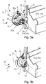
- Fig. 3a shows the assembly and mode of action of the locking elements 14 in the Fig. 3a to 3d . 4, 5a and 5d explained in more detail. So shows Fig. 3a first, as the locking element 14 is inserted in particular in the connecting direction V in the separating edge 12 of a hood part 10a, 10b.
- the construction of the locking element 14 itself is also clearly recognizable.
- This first comprises a central pin 30, which extends in the direction of an axis of rotation D of the locking element 14.
- a disc-like head is attached to the pin 30, from which a contact web 22 extends in the direction of the axis of rotation D and over approximately one third of the length of the pin 30.
- the contact web 22 is C-shaped or circular arc-shaped and comprises two separate by an omission sub-webs 22a, 22b, which extend in the direction of rotation U about the axis of rotation D around. In this case, the contact web 22 rotates the pin 30 by a little more than half.
- the contact web 22 thus forms a closed side 38 of the locking element 14; in Fig. 3a the closed side 38 is arranged according to the left.
- the hood part 10a, 10b facing the right side is then an open side 36th
- the partial webs 22a, 22b each form at the end of the contact web 22 a guide extension 24, which is oriented for insertion into the hood part 10a, 10b in such a way that it points towards the hood part 10a, 10b.
- these guide extensions 24 are oriented for insertion into the hood part 10a, 10b in such a way that it points towards the hood part 10a, 10b.
- a cylindrical Anformung 32 is arranged as a holding head 32.
- the locking element 14 is made in one piece.
- the holding head 32 is as in Fig. 3a shown a receiving chamber 34a, 34b inserted into the separating edge 12 of a hood part 10a, 10b and is held there in a form-fitting manner in the direction of the rotation axis D.
- the two receiving chambers 34a, 34b of the two hood parts 10a, 10b form a common receiving chamber 34 in the assembled state.
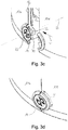
- Fig. 3c It is shown how the two hood parts 10a, 10b are placed against one another in the direction of connection V.
- the other hood part 10a, 10b a C-shaped groove 16, in which engage the guide projections 24 when fitting.
- Fig. 3d shows finally the juxtaposed and mounted hood parts 10a, 10b, wherein for fixing the two hood parts 10a, 10b to each other, the locking element 14 has been transferred by 90 °, ie by means of a quarter turn, in a closed position.
- the two hood part 10a, 10b are now firmly connected.
- Fig. 4 shows the device cover 2 in a plan view, ie the top 46.
- Die Fig. 5a and 5b show the device cover 2 in a sectional view along the in Fig. 4 marked section plane A - A. showing Fig. 5a the locking element 14 in the open position while Fig. 5b the locking element 14 in the closed position shows.
- the guide groove 20 is here also divided by a solid portion, whereby the guide groove 20 is formed only partially annular.
- two stops 28 are formed for the contact web 22, in particular to prevent over-rotation.
- the groove 16 in the second hood part 10b is divided into two sections 20a, 20b. In each one of the two positions open and closed is then in each case a guide extension 24 on the corresponding stop 28 at.
- the device 4 also includes two air ports 42, which are as in the in Fig. 6 shown top view of the device cover 2 are arranged at an angle W1 of 90 ° to each other.
- the air connections 42 are arranged on a lateral surface 44 of the device hood 2 and point in the radial direction R with respect to the device 4.
- connecting pieces 48 or adapters are attached to the air connections 42, as in FIGS Fig. 7a to 7d and 8a to 8d is shown.
- the two air connections 42 are hereby formed on only one of the two hood parts 10a, 10b, while the other hood part 10a, 10b is free of air connections 42. This results in various combination options for setting the direction in which a respective air connection 42 has.
- the connecting pieces 48 are themselves each formed at an angle with an angle W2.
- Fig. 7a to 7d 90 ° angled connection piece 48 connected to the air ports 42, so that either a connection from above or from below is possible.
- the Fig. 8a to d show in each case the device cover 2 in a plan view, with 45 ° angled connection piece 48 to the air ports 42.
- a connection of pipes from various lateral directions is possible.
- Fig. 8c a connection of both air ports 42 in the rearward direction of the device 4, in Fig. 8d but both times from the side.
- the Fig. 8a and b show combinations of lateral and rearward orientation of the air ports 42.
Landscapes
- Engineering & Computer Science (AREA)
- Physics & Mathematics (AREA)
- Thermal Sciences (AREA)
- Chemical & Material Sciences (AREA)
- Combustion & Propulsion (AREA)
- Mechanical Engineering (AREA)
- General Engineering & Computer Science (AREA)
- Snaps, Bayonet Connections, Set Pins, And Snap Rings (AREA)
Claims (12)
- Capot d'appareil (2), en particulier pour une pompe à chaleur (4) qui s'étend dans une direction axiale (A) et qui présente une première et une deuxième partie de capot (10, 10a, 10b), les parties de capot (10a, 10b) s'appliquant l'une contre l'autre dans l'état monté au niveau de bords de séparation (12), et pouvant être écartées l'une de l'autre dans une direction de connexion (V) perpendiculairement à la direction axiale (A), un verrouillage desserrable avec au moins un élément de verrouillage rotatif (14) étant disposé dans l'état monté pour la fixation l'une à l'autre des parties de capot (10a, 10b),
caractérisé en ce que
l'élément de verrouillage (14) peut être transféré de manière réversible par rotation autour d'un axe de rotation (D) entre une position ouverte et une position fermée et en ce que, dans la position ouverte, les parties de capot (10a, 10b) peuvent être écartées l'une de l'autre, en ce que les parties de capot (10a, 10b) présentent chacune une rainure (16) qui est accessible par le biais du bord de séparation (12), les rainures (16) formant une rainure de guidage commune (20) pour guider l'élément de verrouillage (14) lors du transfert entre l'état ouvert et l'état fermé, en ce que l'élément de verrouillage (14) présente une nervure d'appui (22) qui est guidée dans la rainure de guidage (20) et qui s'étend autour de l'axe de rotation (D) et en ce que la rainure de guidage (20) est réalisée seulement en partie dans l'une des parties de capot (10a, 10b) et est interrompue dans deux portions partielles (20a, 20b) et constitue au moins une butée (28) pour la nervure d'appui (22). - Capot d'appareil (2) selon la revendication précédente,
caractérisé en ce que
l'élément de verrouillage (14), lors de l'écartement, est retenu de manière imperdable au niveau de l'une des parties de capot (10a, 10b) et de préférence en ce que l'élément de verrouillage (14) est retenu par engagement par correspondance de formes dans l'état inséré dans la direction de l'axe de rotation (D). - Capot d'appareil (2) selon l'une quelconque des revendications précédentes,
caractérisé en ce que
l'élément de verrouillage (14), dans l'état monté des parties de capot (10a, 10b), est disposé entre les bords de séparation (12), en particulier est saisi sur son pourtour par ceux-ci. - Capot d'appareil (2) selon l'une quelconque des revendications précédentes,
caractérisé en ce que
la nervure d'appui (22), dans la position ouverte, est introduite dans la rainure (16) de l'une des parties de capot (10a, 10b). - Capot d'appareil (2) selon l'une quelconque des revendications précédentes,
caractérisé en ce que
la nervure d'appui (22) constitue au moins une saillie de guidage (24) qui, dans la position ouverte, pénètre dans la rainure (16) de la deuxième partie de capot (10b). - Capot d'appareil (2) selon l'une quelconque des revendications précédentes,
caractérisé en ce que
la nervure d'appui (22), lors du transfert de la position ouverte dans la position fermée, entre en partie depuis la rainure (16) de l'une des parties de capot (10a, 10b) dans la rainure (16) de l'autre partie de capot (10a, 10b). - Capot d'appareil (2) selon l'une quelconque des revendications précédentes,
caractérisé en ce que
pour la fixation dans les deux parties de capot (10a, 10b), un contour de retenue vient en prise par l'arrière dans la position fermée de la nervure d'appui (22), lequel est réalisé par la rainure de guidage (20). - Capot d'appareil (2) selon l'une quelconque des revendications précédentes,
caractérisé en ce que
la nervure d'appui (22) est réalisée sous forme fendue, pour réaliser plusieurs, en particulier deux, nervures partielles (22a, 22b). - Capot d'appareil (2) selon l'une quelconque des revendications précédentes,
caractérisé en ce que
les deux parties de capot (10a, 10b) présentent à chaque fois une chambre de réception (34,a 34b) dans le bord de séparation (12) et les chambres de réception (34a, 34b) forment un logement (34) dans l'état monté, dans lequel est retenu par engagement par correspondance de formes l'élément de verrouillage (14) qui peut de ce fait tourner autour de l'axe de rotation (D). - Capot d'appareil (2) selon l'une quelconque des revendications précédentes,
caractérisé en ce que
l'élément de verrouillage (14) présente un côté ouvert et un côté fermé (36, 38), et une nervure d'appui (22) qui est disposée seulement sur le côté fermé (38), et
en ce que l'élément de verrouillage (14) peut être inséré avec le côté ouvert (36) dans le bord de séparation (12) de l'une des parties de capot (10a, 10b). - Capot d'appareil (2) selon l'une quelconque des revendications précédentes,
caractérisé en ce que
l'une des parties de capot (10a, 10b) présente une pluralité de raccords d'air (42) et l'autre est exempte de raccords d'air (42). - Pompe à chaleur (4) comprenant un corps de base (6) qui comprend un accumulateur d'eau et sur lequel sont disposés une pluralité de composants (8), les composants (8) étant recouverts par un capot d'appareil (2) selon l'une quelconque des revendications précédentes.
Applications Claiming Priority (1)
| Application Number | Priority Date | Filing Date | Title |
|---|---|---|---|
| DE102015203780 | 2015-03-03 |
Publications (2)
| Publication Number | Publication Date |
|---|---|
| EP3064857A1 EP3064857A1 (fr) | 2016-09-07 |
| EP3064857B1 true EP3064857B1 (fr) | 2018-06-13 |
Family
ID=55650061
Family Applications (1)
| Application Number | Title | Priority Date | Filing Date |
|---|---|---|---|
| EP16158142.6A Active EP3064857B1 (fr) | 2015-03-03 | 2016-03-01 | Capot d'appareil |
Country Status (1)
| Country | Link |
|---|---|
| EP (1) | EP3064857B1 (fr) |
Cited By (4)
| Publication number | Priority date | Publication date | Assignee | Title |
|---|---|---|---|---|
| CN108895725A (zh) * | 2018-07-24 | 2018-11-27 | 珠海格力电器股份有限公司 | 一种蒸发器换热装置及整体式空气能热水器 |
| EP4191078A1 (fr) * | 2021-12-02 | 2023-06-07 | Hilti Aktiengesellschaft | Système de connexion comprenant un connecteur de panneau de type rotatif |
| EP4428468A1 (fr) * | 2023-03-10 | 2024-09-11 | Stiebel Eltron GmbH & Co. KG | Pompe à chaleur à eau chaude |
| EP4600578A4 (fr) * | 2023-12-18 | 2025-11-05 | Wuhu Midea Smart Kitchen Appliance Mfg Co Ltd | Ensemble tête pour chauffe-eau à pompe à chaleur, et chauffe-eau à pompe à chaleur |
Families Citing this family (1)
| Publication number | Priority date | Publication date | Assignee | Title |
|---|---|---|---|---|
| CN107202421A (zh) * | 2017-05-25 | 2017-09-26 | 海宁金能热水器有限公司 | 一种具有减震功能的便移式空气源热水器 |
Family Cites Families (4)
| Publication number | Priority date | Publication date | Assignee | Title |
|---|---|---|---|---|
| DE9315116U1 (de) * | 1993-10-06 | 1995-02-09 | Sorg, Gottfried, 75378 Bad Liebenzell | Bauelemente |
| GB9903181D0 (en) * | 1999-02-13 | 1999-04-07 | Atkinson Design Ass Ltd | Fastener |
| DE202006004298U1 (de) * | 2006-03-17 | 2006-05-11 | Ik - Interklimat S.P.A. | Einfach zu bedienende Vorrichtung zum Einhängen von nebeneinanderliegenden Paneelen |
| US8991638B2 (en) | 2011-08-17 | 2015-03-31 | General Electric Company | Water seepage abatement in water heaters |
-
2016
- 2016-03-01 EP EP16158142.6A patent/EP3064857B1/fr active Active
Non-Patent Citations (1)
| Title |
|---|
| None * |
Cited By (5)
| Publication number | Priority date | Publication date | Assignee | Title |
|---|---|---|---|---|
| CN108895725A (zh) * | 2018-07-24 | 2018-11-27 | 珠海格力电器股份有限公司 | 一种蒸发器换热装置及整体式空气能热水器 |
| EP4191078A1 (fr) * | 2021-12-02 | 2023-06-07 | Hilti Aktiengesellschaft | Système de connexion comprenant un connecteur de panneau de type rotatif |
| WO2023099218A1 (fr) * | 2021-12-02 | 2023-06-08 | Hilti Aktiengesellschaft | Système de jonction comprenant un élément de jonction de panneau du type à rotation |
| EP4428468A1 (fr) * | 2023-03-10 | 2024-09-11 | Stiebel Eltron GmbH & Co. KG | Pompe à chaleur à eau chaude |
| EP4600578A4 (fr) * | 2023-12-18 | 2025-11-05 | Wuhu Midea Smart Kitchen Appliance Mfg Co Ltd | Ensemble tête pour chauffe-eau à pompe à chaleur, et chauffe-eau à pompe à chaleur |
Also Published As
| Publication number | Publication date |
|---|---|
| EP3064857A1 (fr) | 2016-09-07 |
Similar Documents
| Publication | Publication Date | Title |
|---|---|---|
| EP3064857B1 (fr) | Capot d'appareil | |
| DE3235554A1 (de) | Steckkupplung fuer mehradrige hydraulische oder pneumatische kabel | |
| EP3586415B1 (fr) | Accouplement à fiche avec antitraction pour un câble de raccordement | |
| EP2096973B1 (fr) | Raccord de tuyau télescopique pour tuyaux d'aspiration ou manches d'aspirateurs | |
| DE202019103390U1 (de) | Linearantrieb mit Lageausrichtungsmitteln zwischen Führungsrohr und Spindelmutter | |
| DE19837767C2 (de) | Einrichtung zum Verbinden von hydraulischen oder pneumatischen Komponenten, insbesondere von Elektromagnetventilen miteinander | |
| DE102016124805B4 (de) | Membranventil | |
| DE68923618T2 (de) | Befestigung eines Bündels von länglichen Gegenständen oder eines nichtkreisförmigen länglichen Gegenstandes auf einer Unterlage. | |
| EP2177690B1 (fr) | Dispositif de retenue pour un support de sécurité, notamment pour parois ou des filets de sécurité | |
| EP2196584A1 (fr) | Distributeur pour une installation de conduite d'eau | |
| EP0579578A1 (fr) | Plaque de raccordement à une structure de support | |
| EP3392419A1 (fr) | Système de fixation | |
| WO2004093603A1 (fr) | Element de liaison et systeme de bati | |
| DE10225403B4 (de) | Ständerwerk | |
| EP1382509A1 (fr) | Colonne de direction | |
| DE10240999A1 (de) | Vorrichtung zum winkligen Verbinden von Montageschienen | |
| AT523046B1 (de) | Vorrichtung zum Verbinden von Rohren | |
| EP0303905B1 (fr) | Raccord à brides | |
| EP0455972B1 (fr) | Dispositif support pour l'accouplement simultané de plusieurs raccords parallèles pour fluide | |
| EP2578891B1 (fr) | Adapteur | |
| DE29808857U1 (de) | Steckdosenleiste | |
| EP3045743A1 (fr) | Fixation de structure porteuse pour un repartiteur de fluide, agencement de montage et procede de montage d'un repartiteur de fluide | |
| EP3101318B1 (fr) | Module de vanne | |
| EP2905799B1 (fr) | Système constitué d'un appareil de base et d'un élément auxiliaire | |
| DE4222504A1 (de) | Halterung für Spinn- oder Zwirnspindeln |
Legal Events
| Date | Code | Title | Description |
|---|---|---|---|
| PUAI | Public reference made under article 153(3) epc to a published international application that has entered the european phase |
Free format text: ORIGINAL CODE: 0009012 |
|
| AK | Designated contracting states |
Kind code of ref document: A1 Designated state(s): AL AT BE BG CH CY CZ DE DK EE ES FI FR GB GR HR HU IE IS IT LI LT LU LV MC MK MT NL NO PL PT RO RS SE SI SK SM TR |
|
| AX | Request for extension of the european patent |
Extension state: BA ME |
|
| STAA | Information on the status of an ep patent application or granted ep patent |
Free format text: STATUS: REQUEST FOR EXAMINATION WAS MADE |
|
| 17P | Request for examination filed |
Effective date: 20170303 |
|
| RBV | Designated contracting states (corrected) |
Designated state(s): AL AT BE BG CH CY CZ DE DK EE ES FI FR GB GR HR HU IE IS IT LI LT LU LV MC MK MT NL NO PL PT RO RS SE SI SK SM TR |
|
| GRAP | Despatch of communication of intention to grant a patent |
Free format text: ORIGINAL CODE: EPIDOSNIGR1 |
|
| STAA | Information on the status of an ep patent application or granted ep patent |
Free format text: STATUS: GRANT OF PATENT IS INTENDED |
|
| RIC1 | Information provided on ipc code assigned before grant |
Ipc: F24H 9/02 20060101ALI20171206BHEP Ipc: F24H 1/18 20060101ALI20171206BHEP Ipc: F24H 4/04 20060101AFI20171206BHEP Ipc: F16B 5/10 20060101ALI20171206BHEP Ipc: F16B 5/00 20060101ALI20171206BHEP |
|
| INTG | Intention to grant announced |
Effective date: 20180109 |
|
| GRAS | Grant fee paid |
Free format text: ORIGINAL CODE: EPIDOSNIGR3 |
|
| GRAA | (expected) grant |
Free format text: ORIGINAL CODE: 0009210 |
|
| STAA | Information on the status of an ep patent application or granted ep patent |
Free format text: STATUS: THE PATENT HAS BEEN GRANTED |
|
| AK | Designated contracting states |
Kind code of ref document: B1 Designated state(s): AL AT BE BG CH CY CZ DE DK EE ES FI FR GB GR HR HU IE IS IT LI LT LU LV MC MK MT NL NO PL PT RO RS SE SI SK SM TR |
|
| REG | Reference to a national code |
Ref country code: GB Ref legal event code: FG4D Free format text: NOT ENGLISH |
|
| REG | Reference to a national code |
Ref country code: CH Ref legal event code: EP Ref country code: AT Ref legal event code: REF Ref document number: 1008906 Country of ref document: AT Kind code of ref document: T Effective date: 20180615 |
|
| REG | Reference to a national code |
Ref country code: IE Ref legal event code: FG4D Free format text: LANGUAGE OF EP DOCUMENT: GERMAN |
|
| REG | Reference to a national code |
Ref country code: DE Ref legal event code: R096 Ref document number: 502016001208 Country of ref document: DE |
|
| REG | Reference to a national code |
Ref country code: CH Ref legal event code: NV Representative=s name: E. BLUM AND CO. AG PATENT- UND MARKENANWAELTE , CH |
|
| REG | Reference to a national code |
Ref country code: NL Ref legal event code: MP Effective date: 20180613 |
|
| REG | Reference to a national code |
Ref country code: LT Ref legal event code: MG4D |
|
| PG25 | Lapsed in a contracting state [announced via postgrant information from national office to epo] |
Ref country code: CY Free format text: LAPSE BECAUSE OF FAILURE TO SUBMIT A TRANSLATION OF THE DESCRIPTION OR TO PAY THE FEE WITHIN THE PRESCRIBED TIME-LIMIT Effective date: 20180613 Ref country code: SE Free format text: LAPSE BECAUSE OF FAILURE TO SUBMIT A TRANSLATION OF THE DESCRIPTION OR TO PAY THE FEE WITHIN THE PRESCRIBED TIME-LIMIT Effective date: 20180613 Ref country code: FI Free format text: LAPSE BECAUSE OF FAILURE TO SUBMIT A TRANSLATION OF THE DESCRIPTION OR TO PAY THE FEE WITHIN THE PRESCRIBED TIME-LIMIT Effective date: 20180613 Ref country code: BG Free format text: LAPSE BECAUSE OF FAILURE TO SUBMIT A TRANSLATION OF THE DESCRIPTION OR TO PAY THE FEE WITHIN THE PRESCRIBED TIME-LIMIT Effective date: 20180913 Ref country code: NO Free format text: LAPSE BECAUSE OF FAILURE TO SUBMIT A TRANSLATION OF THE DESCRIPTION OR TO PAY THE FEE WITHIN THE PRESCRIBED TIME-LIMIT Effective date: 20180913 Ref country code: ES Free format text: LAPSE BECAUSE OF FAILURE TO SUBMIT A TRANSLATION OF THE DESCRIPTION OR TO PAY THE FEE WITHIN THE PRESCRIBED TIME-LIMIT Effective date: 20180613 Ref country code: LT Free format text: LAPSE BECAUSE OF FAILURE TO SUBMIT A TRANSLATION OF THE DESCRIPTION OR TO PAY THE FEE WITHIN THE PRESCRIBED TIME-LIMIT Effective date: 20180613 |
|
| PG25 | Lapsed in a contracting state [announced via postgrant information from national office to epo] |
Ref country code: GR Free format text: LAPSE BECAUSE OF FAILURE TO SUBMIT A TRANSLATION OF THE DESCRIPTION OR TO PAY THE FEE WITHIN THE PRESCRIBED TIME-LIMIT Effective date: 20180914 Ref country code: RS Free format text: LAPSE BECAUSE OF FAILURE TO SUBMIT A TRANSLATION OF THE DESCRIPTION OR TO PAY THE FEE WITHIN THE PRESCRIBED TIME-LIMIT Effective date: 20180613 Ref country code: HR Free format text: LAPSE BECAUSE OF FAILURE TO SUBMIT A TRANSLATION OF THE DESCRIPTION OR TO PAY THE FEE WITHIN THE PRESCRIBED TIME-LIMIT Effective date: 20180613 Ref country code: LV Free format text: LAPSE BECAUSE OF FAILURE TO SUBMIT A TRANSLATION OF THE DESCRIPTION OR TO PAY THE FEE WITHIN THE PRESCRIBED TIME-LIMIT Effective date: 20180613 |
|
| PG25 | Lapsed in a contracting state [announced via postgrant information from national office to epo] |
Ref country code: NL Free format text: LAPSE BECAUSE OF FAILURE TO SUBMIT A TRANSLATION OF THE DESCRIPTION OR TO PAY THE FEE WITHIN THE PRESCRIBED TIME-LIMIT Effective date: 20180613 |
|
| PG25 | Lapsed in a contracting state [announced via postgrant information from national office to epo] |
Ref country code: RO Free format text: LAPSE BECAUSE OF FAILURE TO SUBMIT A TRANSLATION OF THE DESCRIPTION OR TO PAY THE FEE WITHIN THE PRESCRIBED TIME-LIMIT Effective date: 20180613 Ref country code: CZ Free format text: LAPSE BECAUSE OF FAILURE TO SUBMIT A TRANSLATION OF THE DESCRIPTION OR TO PAY THE FEE WITHIN THE PRESCRIBED TIME-LIMIT Effective date: 20180613 Ref country code: PL Free format text: LAPSE BECAUSE OF FAILURE TO SUBMIT A TRANSLATION OF THE DESCRIPTION OR TO PAY THE FEE WITHIN THE PRESCRIBED TIME-LIMIT Effective date: 20180613 Ref country code: EE Free format text: LAPSE BECAUSE OF FAILURE TO SUBMIT A TRANSLATION OF THE DESCRIPTION OR TO PAY THE FEE WITHIN THE PRESCRIBED TIME-LIMIT Effective date: 20180613 Ref country code: IS Free format text: LAPSE BECAUSE OF FAILURE TO SUBMIT A TRANSLATION OF THE DESCRIPTION OR TO PAY THE FEE WITHIN THE PRESCRIBED TIME-LIMIT Effective date: 20181013 Ref country code: SK Free format text: LAPSE BECAUSE OF FAILURE TO SUBMIT A TRANSLATION OF THE DESCRIPTION OR TO PAY THE FEE WITHIN THE PRESCRIBED TIME-LIMIT Effective date: 20180613 |
|
| PG25 | Lapsed in a contracting state [announced via postgrant information from national office to epo] |
Ref country code: IT Free format text: LAPSE BECAUSE OF FAILURE TO SUBMIT A TRANSLATION OF THE DESCRIPTION OR TO PAY THE FEE WITHIN THE PRESCRIBED TIME-LIMIT Effective date: 20180613 Ref country code: SM Free format text: LAPSE BECAUSE OF FAILURE TO SUBMIT A TRANSLATION OF THE DESCRIPTION OR TO PAY THE FEE WITHIN THE PRESCRIBED TIME-LIMIT Effective date: 20180613 |
|
| REG | Reference to a national code |
Ref country code: DE Ref legal event code: R097 Ref document number: 502016001208 Country of ref document: DE |
|
| PLBE | No opposition filed within time limit |
Free format text: ORIGINAL CODE: 0009261 |
|
| STAA | Information on the status of an ep patent application or granted ep patent |
Free format text: STATUS: NO OPPOSITION FILED WITHIN TIME LIMIT |
|
| 26N | No opposition filed |
Effective date: 20190314 |
|
| PG25 | Lapsed in a contracting state [announced via postgrant information from national office to epo] |
Ref country code: SI Free format text: LAPSE BECAUSE OF FAILURE TO SUBMIT A TRANSLATION OF THE DESCRIPTION OR TO PAY THE FEE WITHIN THE PRESCRIBED TIME-LIMIT Effective date: 20180613 Ref country code: DK Free format text: LAPSE BECAUSE OF FAILURE TO SUBMIT A TRANSLATION OF THE DESCRIPTION OR TO PAY THE FEE WITHIN THE PRESCRIBED TIME-LIMIT Effective date: 20180613 |
|
| PG25 | Lapsed in a contracting state [announced via postgrant information from national office to epo] |
Ref country code: MC Free format text: LAPSE BECAUSE OF FAILURE TO SUBMIT A TRANSLATION OF THE DESCRIPTION OR TO PAY THE FEE WITHIN THE PRESCRIBED TIME-LIMIT Effective date: 20180613 |
|
| PG25 | Lapsed in a contracting state [announced via postgrant information from national office to epo] |
Ref country code: LU Free format text: LAPSE BECAUSE OF NON-PAYMENT OF DUE FEES Effective date: 20190301 Ref country code: AL Free format text: LAPSE BECAUSE OF FAILURE TO SUBMIT A TRANSLATION OF THE DESCRIPTION OR TO PAY THE FEE WITHIN THE PRESCRIBED TIME-LIMIT Effective date: 20180613 |
|
| REG | Reference to a national code |
Ref country code: BE Ref legal event code: MM Effective date: 20190331 |
|
| PG25 | Lapsed in a contracting state [announced via postgrant information from national office to epo] |
Ref country code: IE Free format text: LAPSE BECAUSE OF NON-PAYMENT OF DUE FEES Effective date: 20190301 |
|
| PG25 | Lapsed in a contracting state [announced via postgrant information from national office to epo] |
Ref country code: BE Free format text: LAPSE BECAUSE OF NON-PAYMENT OF DUE FEES Effective date: 20190331 |
|
| PG25 | Lapsed in a contracting state [announced via postgrant information from national office to epo] |
Ref country code: TR Free format text: LAPSE BECAUSE OF FAILURE TO SUBMIT A TRANSLATION OF THE DESCRIPTION OR TO PAY THE FEE WITHIN THE PRESCRIBED TIME-LIMIT Effective date: 20180613 |
|
| PG25 | Lapsed in a contracting state [announced via postgrant information from national office to epo] |
Ref country code: MT Free format text: LAPSE BECAUSE OF FAILURE TO SUBMIT A TRANSLATION OF THE DESCRIPTION OR TO PAY THE FEE WITHIN THE PRESCRIBED TIME-LIMIT Effective date: 20180613 Ref country code: PT Free format text: LAPSE BECAUSE OF FAILURE TO SUBMIT A TRANSLATION OF THE DESCRIPTION OR TO PAY THE FEE WITHIN THE PRESCRIBED TIME-LIMIT Effective date: 20181015 |
|
| GBPC | Gb: european patent ceased through non-payment of renewal fee |
Effective date: 20200301 |
|
| PG25 | Lapsed in a contracting state [announced via postgrant information from national office to epo] |
Ref country code: GB Free format text: LAPSE BECAUSE OF NON-PAYMENT OF DUE FEES Effective date: 20200301 |
|
| PG25 | Lapsed in a contracting state [announced via postgrant information from national office to epo] |
Ref country code: HU Free format text: LAPSE BECAUSE OF FAILURE TO SUBMIT A TRANSLATION OF THE DESCRIPTION OR TO PAY THE FEE WITHIN THE PRESCRIBED TIME-LIMIT; INVALID AB INITIO Effective date: 20160301 |
|
| PG25 | Lapsed in a contracting state [announced via postgrant information from national office to epo] |
Ref country code: MK Free format text: LAPSE BECAUSE OF FAILURE TO SUBMIT A TRANSLATION OF THE DESCRIPTION OR TO PAY THE FEE WITHIN THE PRESCRIBED TIME-LIMIT Effective date: 20180613 |
|
| P01 | Opt-out of the competence of the unified patent court (upc) registered |
Effective date: 20230527 |
|
| PGFP | Annual fee paid to national office [announced via postgrant information from national office to epo] |
Ref country code: DE Payment date: 20250326 Year of fee payment: 10 |
|
| PGFP | Annual fee paid to national office [announced via postgrant information from national office to epo] |
Ref country code: AT Payment date: 20250319 Year of fee payment: 10 |
|
| PGFP | Annual fee paid to national office [announced via postgrant information from national office to epo] |
Ref country code: FR Payment date: 20250324 Year of fee payment: 10 |
|
| PGFP | Annual fee paid to national office [announced via postgrant information from national office to epo] |
Ref country code: CH Payment date: 20250401 Year of fee payment: 10 |