EP4428468A1 - Pompe à chaleur à eau chaude - Google Patents
Pompe à chaleur à eau chaude Download PDFInfo
- Publication number
- EP4428468A1 EP4428468A1 EP24157540.6A EP24157540A EP4428468A1 EP 4428468 A1 EP4428468 A1 EP 4428468A1 EP 24157540 A EP24157540 A EP 24157540A EP 4428468 A1 EP4428468 A1 EP 4428468A1
- Authority
- EP
- European Patent Office
- Prior art keywords
- segment
- hot water
- heat pump
- water heat
- air
- Prior art date
- Legal status (The legal status is an assumption and is not a legal conclusion. Google has not performed a legal analysis and makes no representation as to the accuracy of the status listed.)
- Pending
Links
- XLYOFNOQVPJJNP-UHFFFAOYSA-N water Substances O XLYOFNOQVPJJNP-UHFFFAOYSA-N 0.000 title claims abstract description 64
- 239000003507 refrigerant Substances 0.000 claims description 15
- 238000009423 ventilation Methods 0.000 claims description 8
- 238000006073 displacement reaction Methods 0.000 claims description 3
- 239000002826 coolant Substances 0.000 abstract description 4
- 239000003570 air Substances 0.000 description 104
- 238000010438 heat treatment Methods 0.000 description 7
- 239000003651 drinking water Substances 0.000 description 4
- 235000020188 drinking water Nutrition 0.000 description 4
- 238000009434 installation Methods 0.000 description 4
- 238000012423 maintenance Methods 0.000 description 4
- 238000010257 thawing Methods 0.000 description 3
- 229910000831 Steel Inorganic materials 0.000 description 2
- 230000003287 optical effect Effects 0.000 description 2
- 239000010959 steel Substances 0.000 description 2
- 239000012080 ambient air Substances 0.000 description 1
- 230000000712 assembly Effects 0.000 description 1
- 238000000429 assembly Methods 0.000 description 1
- 230000015572 biosynthetic process Effects 0.000 description 1
- 230000007797 corrosion Effects 0.000 description 1
- 238000005260 corrosion Methods 0.000 description 1
- 230000007423 decrease Effects 0.000 description 1
- 230000001419 dependent effect Effects 0.000 description 1
- 239000002320 enamel (paints) Substances 0.000 description 1
- 239000000284 extract Substances 0.000 description 1
- 238000000605 extraction Methods 0.000 description 1
- 238000009413 insulation Methods 0.000 description 1
- 239000002184 metal Substances 0.000 description 1
- 230000001681 protective effect Effects 0.000 description 1
- 230000011664 signaling Effects 0.000 description 1
- 239000002918 waste heat Substances 0.000 description 1
Images


Classifications
-
- F—MECHANICAL ENGINEERING; LIGHTING; HEATING; WEAPONS; BLASTING
- F24—HEATING; RANGES; VENTILATING
- F24H—FLUID HEATERS, e.g. WATER OR AIR HEATERS, HAVING HEAT-GENERATING MEANS, e.g. HEAT PUMPS, IN GENERAL
- F24H4/00—Fluid heaters characterised by the use of heat pumps
- F24H4/02—Water heaters
- F24H4/04—Storage heaters
-
- F—MECHANICAL ENGINEERING; LIGHTING; HEATING; WEAPONS; BLASTING
- F24—HEATING; RANGES; VENTILATING
- F24D—DOMESTIC- OR SPACE-HEATING SYSTEMS, e.g. CENTRAL HEATING SYSTEMS; DOMESTIC HOT-WATER SUPPLY SYSTEMS; ELEMENTS OR COMPONENTS THEREFOR
- F24D17/00—Domestic hot-water supply systems
- F24D17/02—Domestic hot-water supply systems using heat pumps
-
- F—MECHANICAL ENGINEERING; LIGHTING; HEATING; WEAPONS; BLASTING
- F24—HEATING; RANGES; VENTILATING
- F24H—FLUID HEATERS, e.g. WATER OR AIR HEATERS, HAVING HEAT-GENERATING MEANS, e.g. HEAT PUMPS, IN GENERAL
- F24H9/00—Details
- F24H9/02—Casings; Cover lids; Ornamental panels
Definitions
- the present invention relates to a hot water heat pump and in particular to an indoor hot water heat pump.
- Heat pumps are generally well known. They absorb thermal energy from a reservoir with a lower temperature, particularly from the environment, using technical work, usually by means of a compressor, and transfer this as useful heat to a system to be heated at a higher temperature.
- An example of a well-known heat pump is the WWK hot water heat pump from the manufacturer Stiebel Eltron.
- Such a device enables efficient hot water supply to several outlets using renewable energy.
- the device extracts heat from the air it draws in.
- this heat is used to heat the water in the domestic hot water tank.
- the electrical energy requirement and the heating time for heating drinking water depend on the temperature of the air drawn in. As the air intake temperature drops, the heat pump's heating output drops and the heating time increases.
- the device is designed for indoor installation. The free choice of air inlet and outlet, from the side or from above, offers flexibility in terms of the installation location.
- the device can be installed as a recirculation device and thus efficiently use existing waste heat from, for example, a freezer or other heat generator.
- air ducts can be connected to use outside air as a heat source or to draw in air from another room.
- the ambient air can cool down by 1 °C to 3 °C due to the heat extraction.
- the device also removes moisture from the air, which accumulates as condensate.
- the condensate is Condensate drains out of the device.
- the device has an electronic control with an LC display, on which, for example, the currently available amount of 40 °C warm mixed water can be called up.
- the electronic control makes it easier to set energy-saving settings. Depending on the power supply and your usage behavior, the device automatically heats up to the set target temperature.
- the electric emergency/additional heater takes over the heating of the drinking water.
- External signaling devices can be integrated via the built-in contact input, e.g. a photovoltaic system to use self-generated solar power. After opening a hot water outlet, warm drinking water is pushed out of the device by incoming cold drinking water.
- the heat pump unit is located in the upper part of the device.
- the domestic hot water tank is located in the lower part of the device.
- the domestic hot water tank is equipped with a special enamel coating on the inside to protect it from corrosion and also has a non-consumable external current protective anode.
- a hot water heat pump with a refrigerant circuit, a hot water tank and a housing in which the refrigerant circuit and the hot water tank are arranged wherein the housing has an upper housing part for receiving the refrigerant circuit and a lower housing part for receiving the hot water tank, wherein the upper housing part has a cylindrical wall part and a cover, wherein the cylindrical wall part is formed from a plurality of segments and the cover comprises a locking means, in particular a bayonet lock that can be locked by means of a screw, in order to fix the plurality of segments of the wall part.
- the upper part of the housing therefore consists of several components, all of which can be assembled using a single locking device, in particular a bayonet lock.
- the cover ensures that the other parts of the cylindrical housing, which consist of several segments, Walls can no longer move against each other and therefore provide a stable and secure housing.
- the cover can be removed and access to the entire space of the heat generator can be gained.
- the hot water heat pump has a condensate tray and the cylindrical wall part closes at its lower side with the condensate tray.
- the refrigerant circuit has a fan and the cylindrical wall part has three segments, namely a closed segment, an air intake segment and an air outlet segment.
- the three segments can each cover around 120° of the total 360° of the cylindrical wall. This means that the number of components is low, but without the need for individual complex elements.
- the space enclosed by the upper housing part is divided into two spaces, namely an evaporator space and a machine space, wherein in particular a compressor and a condenser of the refrigerant circuit are arranged in the machine space, wherein the machine space is delimited by the closed segment.
- the air intake segment and the air outlet segment are arranged on opposite sides with respect to a fan and the evaporator.
- the evaporator therefore divides the evaporator chamber approximately in the middle into an air intake chamber and an air outlet chamber, whereby the air flow guided through the evaporator by the fan flows from the air intake chamber into the air outlet chamber.
- the air intake segment and the air outlet segment each have at least a partial ventilation grille. Accordingly, the air flow is possible through the respective ventilation grilles of the respective segments.
- the closed wall segment is not permeable to air, so that the unit is particularly acoustically dampened.
- the size of the ventilation grille is adapted to the air flow over the evaporator.
- the air intake segment and the air outlet segment are displaceable in the circumferential direction of the cylindrical wall part, in particular displaceable on the condensate tray when the closed segment is removed.
- the closed segment is therefore the segment that is assembled last and disassembled first.
- the closed segment can simply be pulled upwards when the fastening elements are loosened, so that the other two segments are released by the removed closed segment.
- the air intake segment and the air outlet segment are displaced by displacement in the circumferential direction into a removal position in which the air intake segment or the air outlet segment is released for removal.
- the air intake segment and the air outlet segment can be secured against removal upwards in the assembly position by a catch or similar, whereby this catch is released by displacement in the circumferential direction. Accordingly, removal, in particular upwards, of the air intake segment and the air outlet segment is then effortlessly possible.
- the cylindrical wall has circumferential ribs.
- the circumferential ribs create an overall aesthetic impression that is not interrupted by the ventilation grille.
- the cylindrical wall can therefore have the same optical appearance on each side without affecting the function of the ventilation grille.
- the ribs for the ventilation grille have an aerodynamic and safety advantage.
- the hot water heat pump 100 is in Figure 1 set up in a room 1. It has a round housing 200 with different areas, a front 201, a rear wall 203, a left side wall 205 and a right side wall 207.
- the front 201, the rear wall 203, the left side wall 205 and the right side wall 207 are designed as one piece.
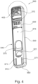
- the front 201 has a control box 500.
- This control box 500 is equipped with a frame 510 and a front area 511 with a groove 512.
- the frame 510 also has a left side area 530, a right side area 540, a frame cover 550 and a frame base 560.
- a controller 400 with a control button 401 is integrated in the control box 500.
- the hot water heat pump 100 also has an upper housing part 210, which consists of a closed segment 220, an air intake segment 230 and an air outlet segment 240.
- the upper housing part 210 offers space for a heat generator, which is designed here as a coolant circuit 300.
- the upper housing part 210 is closed with a cover 250.
- a hot water storage tank 600 is arranged below the upper housing part 210 and is enclosed by the housing 200.
- the switch box 500 located on the hot water heat pump 100 is equipped with a cable passage 526 and a splash wall 528.
- a controller compartment 513 is also provided, in which a controller board 410 can be accommodated.
- the controller board 410 is arranged behind the front area 511 on an inclined plane 523.
- the control button 401 is also arranged below the frame cover 550.
- a bracket 525 for strain relief and a holder 524 for connection terminals are provided in the control box.
- a connection area 351 is provided for a heating element (not shown).
- the frame base 560 is provided further down on the control box 500.
- a steel tank 601 which is enamelled at least on the inside, is surrounded by thermal insulation 602 in the hot water storage tank 600.
- a hot water connection 610, a cold water connection 620 and a circulation connection 640 are also provided.
- An inflow damper 621 is attached inside the steel tank 601 at the cold water connection 620.
- a base 260 is provided under the hot water storage tank 600 and the hot water heat pump 100 has feet 209.
- a defrost tray 261 is arranged below the evaporator 340.
- FIG 3 the upper area of the switch box 500 is shown.
- the first locking receptacle and the second locking receptacle are located in the defrosting tray 261.
- the first locking element 573 and the second locking element 529 engage in the defrosting tray 261 in the use position and the switch box 500 is thus fixed to the top of the defrosting tray 261.
- the radiator located in the hot water tank 600 which is not shown here, has a head and the maintenance frame 570 includes this head in various positions of the control box 500.
- the control chamber 513 is protected against the ingress of water, in particular splash water, by water protection bars 514.
- a water protection bar 514 is attached at least in the right side area 540 of the control box 500.
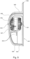
- the hot water heat pump 100 is also equipped with a fan 800, which is Figure 6 is shown.
- the fan 800 has a fan wheel 801 with fan blades 802.
- An air channel 810 is formed by an upper mold part 860 and a lower mold part 870.
- a fan motor 830 is attached to a fan holder 840, whereby the fan holder 840 is held with the upper molded part 860 and the lower molded part 870. Furthermore, an electrical motor connection 833 is guided through the air duct 810. A hub 831 of the fan motor 830 points to a meeting point 844 of the fan holder 840. In the exemplary embodiment, the cover 250 lies above the air duct above the upper molded part 860.
- the lower molded part 870 has recesses 876 which form a clearance for hooks of the condensate tray 261.
- the fan holder 840 is further formed by a retaining ring 841 and various supports 842, here three in the exemplary embodiment.
- a motor mount 843 is also provided.
- the supports 842 run towards the meeting point 844 and are connected there.
- the meeting point 844 is located in the air flow direction 821 behind the fan motor 830. Furthermore, the meeting point 844 and also the fan motor are located behind the retaining ring 841 of the fan holder 840.
- the three supports 842 used in the exemplary embodiment are therefore guided in the air flow direction 821 from the retaining ring 841 to the meeting point 844. From the meeting point 844, the fan motor is attached to the motor mount 843 against the air flow direction 821.
- the fan mount 840 is designed as a single piece with the supports 842 and the motor mount 843, preferably made of plastic or metal.
- the supports 842 are each formed from a post 848 and a web 846, wherein the web 846 is curved.
- the lower mold part 870 further has a lower partial surface 871, a pin 872 and an abutment surface 873.
- a mold surface 874 of the lower mold part 870 is intended to rest against the air blow-out segment 240, approximately on the air intake side wall 245, where no air flows through the air blow-out segment 240.
- the lower molded part 870 has recesses 876.
- a groove 875 is provided to receive the retaining ring 841 of the fan holder 840, which also holds the fan 800.
- Figure 8 illustrates the air flow 820 in the air flow direction 821, which is sucked in by the fan 800 from the evaporator 340, passes through the fan 820 and is transported out of the hot water heat pump 100 again.
- the motor mount 843 on which the fan motor 830 lies and is fastened, is attached to one of the supports 842.
- the motor mount 843 has a height that is suitable for the hub 831 of the fan motor 830 to be at the level of the meeting point 844. This ensures that the meeting point 844 is not directly in the air flow 820, but rather in the air shadow of the fan motor 830.
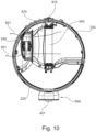
- FIG. 10 A cross section through the upper housing part of the housing 200 is shown in Figure 10 shown.
- the air duct 810 is shown, wherein the diameter of the retaining ring 841, or the open cross section formed by the retaining ring 841, in which the fan wheel 801 is arranged, is smaller than a width or a cross section of the evaporator 340.
- the air duct 810 between the evaporator 340 and the fan 800 is equipped with a cross section that decreases in the air flow direction 821.
- the air channel 810 widens again and the cross-sectional area becomes continuously larger in the course of the air flow direction 821 behind the fan 800.
- the location of the retaining ring 841 or approximately at the level of the groove 875 forms a constriction, like a nozzle.
- the hot water heat pump 100 is constructed such that the air flow direction 821 runs transversely to the switch box 500.
- the evaporator 340 is arranged approximately halfway between the air intake segment 230 and the air outlet segment 240.
- the refrigerant circuit 300 is arranged in the machine room 301.
- the closed segment 220 is in the Figure 11 removed and not shown.
- the air intake segment 230 and the air outlet segment 240 are mounted.
- the rear wall 203 of the hot water heat pump 100 is also located where the air outlet segment 240 and the air intake segment 230 meet.
- the hot water connection 610, the cold water connection 620 and the circulation connection 640 are arranged in the area of the rear wall 203.
- Figure 12 and 13 show the air outlet segment 240. It is formed from several air outlet ribs 242 and air outlet openings 244 through which air can flow. Furthermore, an air intake-side wall 245 is also provided, beyond which the air outlet ribs 242 extend, but which represents a closed area of the air outlet opening 244.
- the air outlet segment 240 is provided with tab receptacles 241 for fastening to the air intake segment 230 and/or the closed segment 220.
- a screw is screwed through the tab receptacle 241 into the air intake segment 230 or the closed segment 220.
- a lid latch 243 is provided on the air outlet segment 240 to provide a connection between the air outlet segment 240 and the lid 250, preferably like a bayonet lock.
- the air intake segment 230 is in Figure 14 and 15
- the air intake segment 230 has air intake fins 232 and air intake openings 234 between the respective air intake fins 232.
- the air intake segment 230 has a cover latch 233 and a tab holder 231, which is intended to receive the tab 221 of the closed segment 220.
- An air intake side wall 235 is also present in the air intake segment 230, which is not permeable to air and is closed between the ribs 236 in the area of the air intake side wall 235.
- the closed segment 220 according to the Figures 16 and 17 is designed as a closed wall. Air should essentially not flow through here. Nevertheless, ribs 226 are attached for optical reasons.
- a partial wall 227 with a cable duct 229 is provided in the closed segment 220.
- a tab 221 is provided for connection to the air intake segment 230 and the air outlet segment 240.
- Cover latches 223 are provided to establish a connection to the cover 250.
Landscapes
- Engineering & Computer Science (AREA)
- Physics & Mathematics (AREA)
- Thermal Sciences (AREA)
- Chemical & Material Sciences (AREA)
- Combustion & Propulsion (AREA)
- Mechanical Engineering (AREA)
- General Engineering & Computer Science (AREA)
- Heat-Pump Type And Storage Water Heaters (AREA)
Applications Claiming Priority (1)
| Application Number | Priority Date | Filing Date | Title |
|---|---|---|---|
| DE102023105993.9A DE102023105993A1 (de) | 2023-03-10 | 2023-03-10 | Warmwasserwärmepumpe |
Publications (1)
| Publication Number | Publication Date |
|---|---|
| EP4428468A1 true EP4428468A1 (fr) | 2024-09-11 |
Family
ID=89940960
Family Applications (1)
| Application Number | Title | Priority Date | Filing Date |
|---|---|---|---|
| EP24157540.6A Pending EP4428468A1 (fr) | 2023-03-10 | 2024-02-14 | Pompe à chaleur à eau chaude |
Country Status (2)
| Country | Link |
|---|---|
| EP (1) | EP4428468A1 (fr) |
| DE (1) | DE102023105993A1 (fr) |
Citations (5)
| Publication number | Priority date | Publication date | Assignee | Title |
|---|---|---|---|---|
| US20130043252A1 (en) * | 2011-08-17 | 2013-02-21 | Jonathan D. Nelson | Water seepage abatement in water heaters |
| CN202885237U (zh) * | 2012-05-23 | 2013-04-17 | 美的集团股份有限公司 | 一种热泵热水器 |
| EP3064857B1 (fr) * | 2015-03-03 | 2018-06-13 | Glen Dimplex Deutschland GmbH | Capot d'appareil |
| US20210041143A1 (en) * | 2018-03-13 | 2021-02-11 | Franco Diederiks | Electric water hearing apparatus |
| EP3904783A1 (fr) * | 2020-04-30 | 2021-11-03 | Compagnie Industrielle des Chauffe-Eau | Installation de chauffage d'eau chaude sanitaire |
-
2023
- 2023-03-10 DE DE102023105993.9A patent/DE102023105993A1/de active Pending
-
2024
- 2024-02-14 EP EP24157540.6A patent/EP4428468A1/fr active Pending
Patent Citations (5)
| Publication number | Priority date | Publication date | Assignee | Title |
|---|---|---|---|---|
| US20130043252A1 (en) * | 2011-08-17 | 2013-02-21 | Jonathan D. Nelson | Water seepage abatement in water heaters |
| CN202885237U (zh) * | 2012-05-23 | 2013-04-17 | 美的集团股份有限公司 | 一种热泵热水器 |
| EP3064857B1 (fr) * | 2015-03-03 | 2018-06-13 | Glen Dimplex Deutschland GmbH | Capot d'appareil |
| US20210041143A1 (en) * | 2018-03-13 | 2021-02-11 | Franco Diederiks | Electric water hearing apparatus |
| EP3904783A1 (fr) * | 2020-04-30 | 2021-11-03 | Compagnie Industrielle des Chauffe-Eau | Installation de chauffage d'eau chaude sanitaire |
Also Published As
| Publication number | Publication date |
|---|---|
| DE102023105993A1 (de) | 2024-09-12 |
Similar Documents
| Publication | Publication Date | Title |
|---|---|---|
| DE102006024682B4 (de) | Geräteschrank mit zwei Kühlkanälen und Anordnung mit dem Geräteschrank | |
| DE202007018397U1 (de) | Thermoelektrische Temperiervorrichtung | |
| DE102008044956A1 (de) | Beleuchtungsvorrichtung zum Einbau in eine Platte | |
| DE10048877C2 (de) | Klimagerät | |
| WO2023089138A1 (fr) | Système de climatisation d'espaces intérieurs d'un bâtiment | |
| EP1816402B1 (fr) | Four | |
| EP4428468A1 (fr) | Pompe à chaleur à eau chaude | |
| EP3682778B1 (fr) | Système de corps de thermorégulation ainsi que système de paroi en applique doté d'un tel système de corps de thermorégulation | |
| DE112015007101T5 (de) | Außeneinheit für Kältekreislaufvorrichtung | |
| DE102023105992A1 (de) | Warmwasserwärmepumpe | |
| DE102023105991A1 (de) | Warmwasserwärmepumpe | |
| EP0287106A1 (fr) | Chauffage pour un sauna | |
| CH658511A5 (de) | Kuehlaggregat fuer ein geschlossenes geraet, insbesondere fuer einen schaltschrank. | |
| DE102020213189B4 (de) | Schaltschrank mit Lüftermodul | |
| DE102007017624B4 (de) | Thermoelektrische Temperiervorrichtung | |
| EP4141341A1 (fr) | Agencement de pompe à chaleur | |
| WO2014124631A1 (fr) | Canal de câble et d'air combiné pour la climatisation d'une armoire de distribution et armoire de distribution correspondante | |
| EP0338343B1 (fr) | Rack de refroidissement pour armoires électriques | |
| DE112019007369B4 (de) | Inneneinheit einer Klimaanlage | |
| DE2714618C3 (de) | Warmwasserbereiter | |
| DE202014104692U1 (de) | Schaltschrank | |
| DE3874514T2 (de) | Haushaltswassererhitzer. | |
| DE69509300T2 (de) | Vorrichtung zum Reduzieren der Kondensierung im Garraum eines Mikrowellenherdes | |
| DE102015223724B3 (de) | Kochgerät mit einer Belüftungseinrichtung | |
| DE10215596B4 (de) | Raum-Aufheizeinheit |
Legal Events
| Date | Code | Title | Description |
|---|---|---|---|
| PUAI | Public reference made under article 153(3) epc to a published international application that has entered the european phase |
Free format text: ORIGINAL CODE: 0009012 |
|
| STAA | Information on the status of an ep patent application or granted ep patent |
Free format text: STATUS: THE APPLICATION HAS BEEN PUBLISHED |
|
| AK | Designated contracting states |
Kind code of ref document: A1 Designated state(s): AL AT BE BG CH CY CZ DE DK EE ES FI FR GB GR HR HU IE IS IT LI LT LU LV MC ME MK MT NL NO PL PT RO RS SE SI SK SM TR |
|
| STAA | Information on the status of an ep patent application or granted ep patent |
Free format text: STATUS: REQUEST FOR EXAMINATION WAS MADE |
|
| 17P | Request for examination filed |
Effective date: 20250311 |