EP3065208A1 - Einzelbrennstoffzelle mit separator und brennstoffzellenstapel - Google Patents
Einzelbrennstoffzelle mit separator und brennstoffzellenstapel Download PDFInfo
- Publication number
- EP3065208A1 EP3065208A1 EP14858941.9A EP14858941A EP3065208A1 EP 3065208 A1 EP3065208 A1 EP 3065208A1 EP 14858941 A EP14858941 A EP 14858941A EP 3065208 A1 EP3065208 A1 EP 3065208A1
- Authority
- EP
- European Patent Office
- Prior art keywords
- fuel cell
- separator
- single fuel
- metallic separator
- joint portion
- Prior art date
- Legal status (The legal status is an assumption and is not a legal conclusion. Google has not performed a legal analysis and makes no representation as to the accuracy of the status listed.)
- Granted
Links
Images



Classifications
-
- H—ELECTRICITY
- H01—ELECTRIC ELEMENTS
- H01M—PROCESSES OR MEANS, e.g. BATTERIES, FOR THE DIRECT CONVERSION OF CHEMICAL ENERGY INTO ELECTRICAL ENERGY
- H01M8/00—Fuel cells; Manufacture thereof
- H01M8/24—Grouping of fuel cells, e.g. stacking of fuel cells
- H01M8/2465—Details of groupings of fuel cells
- H01M8/2483—Details of groupings of fuel cells characterised by internal manifolds
-
- H—ELECTRICITY
- H01—ELECTRIC ELEMENTS
- H01M—PROCESSES OR MEANS, e.g. BATTERIES, FOR THE DIRECT CONVERSION OF CHEMICAL ENERGY INTO ELECTRICAL ENERGY
- H01M8/00—Fuel cells; Manufacture thereof
- H01M8/02—Details
- H01M8/0202—Collectors; Separators, e.g. bipolar separators; Interconnectors
- H01M8/0204—Non-porous and characterised by the material
- H01M8/0206—Metals or alloys
-
- H—ELECTRICITY
- H01—ELECTRIC ELEMENTS
- H01M—PROCESSES OR MEANS, e.g. BATTERIES, FOR THE DIRECT CONVERSION OF CHEMICAL ENERGY INTO ELECTRICAL ENERGY
- H01M8/00—Fuel cells; Manufacture thereof
- H01M8/02—Details
- H01M8/0202—Collectors; Separators, e.g. bipolar separators; Interconnectors
- H01M8/0247—Collectors; Separators, e.g. bipolar separators; Interconnectors characterised by the form
- H01M8/0256—Vias, i.e. connectors passing through the separator material
-
- H—ELECTRICITY
- H01—ELECTRIC ELEMENTS
- H01M—PROCESSES OR MEANS, e.g. BATTERIES, FOR THE DIRECT CONVERSION OF CHEMICAL ENERGY INTO ELECTRICAL ENERGY
- H01M8/00—Fuel cells; Manufacture thereof
- H01M8/02—Details
- H01M8/0271—Sealing or supporting means around electrodes, matrices or membranes
- H01M8/0273—Sealing or supporting means around electrodes, matrices or membranes with sealing or supporting means in the form of a frame
-
- H—ELECTRICITY
- H01—ELECTRIC ELEMENTS
- H01M—PROCESSES OR MEANS, e.g. BATTERIES, FOR THE DIRECT CONVERSION OF CHEMICAL ENERGY INTO ELECTRICAL ENERGY
- H01M8/00—Fuel cells; Manufacture thereof
- H01M8/02—Details
- H01M8/0271—Sealing or supporting means around electrodes, matrices or membranes
- H01M8/028—Sealing means characterised by their material
- H01M8/0282—Inorganic material
-
- H—ELECTRICITY
- H01—ELECTRIC ELEMENTS
- H01M—PROCESSES OR MEANS, e.g. BATTERIES, FOR THE DIRECT CONVERSION OF CHEMICAL ENERGY INTO ELECTRICAL ENERGY
- H01M8/00—Fuel cells; Manufacture thereof
- H01M8/02—Details
- H01M8/0297—Arrangements for joining electrodes, reservoir layers, heat exchange units or bipolar separators to each other
-
- H—ELECTRICITY
- H01—ELECTRIC ELEMENTS
- H01M—PROCESSES OR MEANS, e.g. BATTERIES, FOR THE DIRECT CONVERSION OF CHEMICAL ENERGY INTO ELECTRICAL ENERGY
- H01M8/00—Fuel cells; Manufacture thereof
- H01M8/10—Fuel cells with solid electrolytes
- H01M8/12—Fuel cells with solid electrolytes operating at high temperature, e.g. with stabilised ZrO2 electrolyte
- H01M8/1213—Fuel cells with solid electrolytes operating at high temperature, e.g. with stabilised ZrO2 electrolyte characterised by the electrode/electrolyte combination or the supporting material
-
- H—ELECTRICITY
- H01—ELECTRIC ELEMENTS
- H01M—PROCESSES OR MEANS, e.g. BATTERIES, FOR THE DIRECT CONVERSION OF CHEMICAL ENERGY INTO ELECTRICAL ENERGY
- H01M8/00—Fuel cells; Manufacture thereof
- H01M8/24—Grouping of fuel cells, e.g. stacking of fuel cells
- H01M8/241—Grouping of fuel cells, e.g. stacking of fuel cells with solid or matrix-supported electrolytes
- H01M8/2425—High-temperature cells with solid electrolytes
-
- H—ELECTRICITY
- H01—ELECTRIC ELEMENTS
- H01M—PROCESSES OR MEANS, e.g. BATTERIES, FOR THE DIRECT CONVERSION OF CHEMICAL ENERGY INTO ELECTRICAL ENERGY
- H01M8/00—Fuel cells; Manufacture thereof
- H01M8/24—Grouping of fuel cells, e.g. stacking of fuel cells
- H01M8/2457—Grouping of fuel cells, e.g. stacking of fuel cells with both reactants being gaseous or vaporised
-
- H—ELECTRICITY
- H01—ELECTRIC ELEMENTS
- H01M—PROCESSES OR MEANS, e.g. BATTERIES, FOR THE DIRECT CONVERSION OF CHEMICAL ENERGY INTO ELECTRICAL ENERGY
- H01M8/00—Fuel cells; Manufacture thereof
- H01M8/10—Fuel cells with solid electrolytes
- H01M8/12—Fuel cells with solid electrolytes operating at high temperature, e.g. with stabilised ZrO2 electrolyte
- H01M2008/1293—Fuel cells with solid oxide electrolytes
-
- H—ELECTRICITY
- H01—ELECTRIC ELEMENTS
- H01M—PROCESSES OR MEANS, e.g. BATTERIES, FOR THE DIRECT CONVERSION OF CHEMICAL ENERGY INTO ELECTRICAL ENERGY
- H01M2300/00—Electrolytes
- H01M2300/0017—Non-aqueous electrolytes
- H01M2300/0065—Solid electrolytes
- H01M2300/0068—Solid electrolytes inorganic
- H01M2300/0071—Oxides
- H01M2300/0074—Ion conductive at high temperature
-
- Y—GENERAL TAGGING OF NEW TECHNOLOGICAL DEVELOPMENTS; GENERAL TAGGING OF CROSS-SECTIONAL TECHNOLOGIES SPANNING OVER SEVERAL SECTIONS OF THE IPC; TECHNICAL SUBJECTS COVERED BY FORMER USPC CROSS-REFERENCE ART COLLECTIONS [XRACs] AND DIGESTS
- Y02—TECHNOLOGIES OR APPLICATIONS FOR MITIGATION OR ADAPTATION AGAINST CLIMATE CHANGE
- Y02E—REDUCTION OF GREENHOUSE GAS [GHG] EMISSIONS, RELATED TO ENERGY GENERATION, TRANSMISSION OR DISTRIBUTION
- Y02E60/00—Enabling technologies; Technologies with a potential or indirect contribution to GHG emissions mitigation
- Y02E60/30—Hydrogen technology
- Y02E60/50—Fuel cells
Definitions
- the present invention relates to a separator-fitted single fuel cell, and a fuel cell stack.
- Solid oxide fuel cells that use a solid oxide as an electrolyte have been known.
- An SOFC includes a stack (fuel cell stack) that includes a plurality of stacked single fuel cells each including, for example, an anode and a cathode disposed on the surfaces of a plate-shaped solid electrolyte layer.
- a fuel gas for example, hydrogen
- an oxidant gas for example, oxygen contained in the air
- the fuel cell is used in a state in which it is connected to a separator separating compartments in which a fuel gas and an oxidant gas are present, respectively. Therefore, a technique for joining the single fuel cell to the separator by Ag brazing filler metal or glass is disclosed (see Patent Document 1).
- Patent Document 1 Japanese Patent No. 03466960
- An object of the present invention is to provide a separator-fitted single fuel cell and a fuel cell in which the reliability of joining and sealing between a single fuel cell and a separator is improved.
- the joint portion includes "a protruding portion that protrudes from a gap between the single fuel cell and the first main surface of the metallic separator toward the through hole.” For this reason, a difference in level between the metallic separator and the single fuel cell is reduced by the protruding portion (the protruding portion partially fills a space formed due to the level difference). As a result, defective formation of the sealing portion, which seals the joint portion, (sinking of glass) is prevented and the joint portion can be more reliably sealed by the sealing portion.
- the protruding portion is higher than the second main surface (upper surface) of the metallic separator, the difference in level rather increases and there is a concern that defective formation of the sealing portion (sinking of glass) may occur.
- the metallic separator is joined to the single fuel cell by the joint portion, deformation of the sealing portion is prevented when stress is applied from the outside. Accordingly, it is possible to reduce a possibility of breakage of the sealing portion.
- the sealing portion is disposed closer to the through hole than the joint portion, the joint portion does not directly come into contact with the oxidant gas. Accordingly, the contact between oxygen and the joint portion is prevented. As a result, since diffusion of oxygen into the joint portion is suppressed, it is possible to prevent generation of voids that are generated as a result of the reaction of hydrogen with oxygen.
- each of the metallic separator, the joint portion, and the sealing portion contains A1
- each of the metallic separator, the joint portion, and the sealing portion has a good affinity.
- defective formation of the sealing portion becomes less likely to occur.
- the metallic separator contains Al in an amount of 1.5 mass% or more to 10 mass% or less
- the joint portion contains an oxide or complex oxide of Al in an amount of 1 volume% or more to 25 volume% or less
- the sealing portion contains Al in an amount of 1 mass% or more to 30 mass% or less as reduced to Al 2 O 3
- defective formation of the sealing portion (sinking of glass) becomes less likely to occur.
- the reliability of joining and sealing is improved.
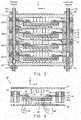
- FIG. 1 is a perspective view of a solid oxide fuel cell stack (fuel cell stack) 10 according to an embodiment of the present invention.
- the solid oxide fuel cell stack 10 generates electric power through the supply of a fuel gas (for example, hydrogen) and an oxidant gas (for example, air (specifically, oxygen contained in the air)).
- a fuel gas for example, hydrogen
- an oxidant gas for example, air (specifically, oxygen contained in the air)
- the solid oxide fuel cell stack 10 includes end plates 11 and 12 and fuel cells 40(1) to 40(4) that are stacked and fixed together by bolts 21, 22 (22a, 22b), and 23 (23a, 23b) and nuts 35.
- FIG. 2 is a schematic cross-sectional view of the solid oxide fuel cell stack 10.
- the solid oxide fuel cell stack 10 is a fuel cell stack that includes the stacked fuel cells 40(1) to 40(4).
- the four fuel cells 40(1) to 40(4) are stacked in the embodiment. However, about 20 to about 60 fuel cells 40 are generally stacked.
- the end plates 11 and 12 and the fuel cells 40(1) to 40(4) include through holes 31, 32 (32a, 32b), and 33 (33a, 33b) for the bolts 21, 22 (22a, 22b), and 23 (23a, 23b), respectively.
- the end plates 11 and 12 are holding plates that press and hold the stacked fuel cells 40(1) to 40(4) and also serve as output terminals for current from the fuel cells 40(1) to 40(4).
- FIG. 3 is a cross-sectional view of the fuel cell 40.
- FIG. 4 is an enlarged cross-sectional view of a portion of the fuel cell 40 that is present in a frame A.
- FIG. 5 is a top view of a single fuel cell 44 and a metallic separator 53 (a separator-fitted single fuel cell 50).
- the fuel cell 40 has the metallic separator 53 and the single fuel cell 44 and includes interconnectors 41 and 45, current collecting members 42a and 42b, and a frame unit 43.
- the single fuel cell 44 is formed by holding a solid electrolyte layer 56 between a cathode (also referred to as a cathode layer) 55 and an anode (also referred to as an anode layer) 57.
- the cathode 55 is disposed on the surface of the solid electrolyte layer 56 facing an oxidant gas path 47
- the anode 57 is disposed on the surface of the solid electrolyte layer 56 facing a fuel gas path 48.
- Perovskite-based oxides such as LSCF (lanthanum strontium cobalt iron oxide) and LSM (lanthanum strontium manganese oxide) may be used for the cathode 55.
- Materials such as YSZ, ScSZ, SDC, GDC, and perovskite-based oxides may be used for the solid electrolyte layer 56.
- Metals are preferably used for the anode 57, and Ni, and Ni-ceramic cermet may be used.
- Each of the interconnectors 41 and 45 is a plate-shaped conductive member (for example, made of a metal such as stainless steel) that can ensure electrical continuity between adjacent single fuel cells 44 and prevent gasses from being mixed with each other between the adjacent single fuel cells 44.
- one interconnector (41 or 45) is disposed between adjacent single fuel cells 44 (since two single fuel cells 44 connected in series share one interconnector).
- the conductive end plates 11 and 12 are disposed instead of the interconnectors 41 and 45, respectively.
- the current collecting member 42a is used to ensure electrical continuity between the interconnector 41 and the cathode 55 of the single fuel cell 44 and includes, for example, protrusions formed on the interconnector 41.
- the current collecting member 42b is used to ensure electrical continuity between the interconnector 41 and the anode 57 of the single fuel cell 44.
- air-permeable nickel felt, nickel mesh, or the like may be used as the current collecting member 42b.
- the frame unit 43 has an opening 46 through which the oxidant gas and the fuel gas flow.
- the opening 46 is hermetically sealed, and the inside thereof is divided into the oxidant gas path 47 through which the oxidant gas flows and the fuel gas path 48 through which the fuel gas flows.
- the frame unit 43 of this embodiment includes a cathode frame 51, an insulating frame 52, the metallic separator 53, and an anode frame 54.
- the cathode frame 51 is a metallic frame disposed on the cathode 55 side, and has the opening 46 at the central portion thereof.
- the oxidant gas path 47 is defined by the opening 46.
- the insulating frame 52 is a frame that electrically insulates the interconnector 41 and the interconnector 45 from each other.
- ceramics such as Al 2 O 3 , mica, vermiculite, or the like may be used for the insulating frame 52, and the insulating frame 52 has the opening 46 at the central portion thereof.
- the oxidant gas path 47 is defined by the opening 46.
- the insulating frame 52 is disposed between the interconnectors 41 and 45 so that one surface of the insulating frame 52 comes into contact with the cathode frame 51 and the other surface thereof comes into contact with the metallic separator 53. As a result, the interconnectors 41 and 45 are electrically insulated from each other by the insulating frame 52.
- the metallic separator 53 is a frame-shaped metallic thin plate (for example, thickness: 0.1 mm) having a through hole 58.
- the metallic separator 53 is a metallic frame that is attached to the solid electrolyte layer 56 of the single fuel cell 44 and prevents the oxidant gas and the fuel gas from being mixed with each other.
- the space in the opening 46 of the frame unit 43 is divided into the oxidant gas path 47 and the fuel gas path 48 by the metallic separator 53, so that the mixing of the oxidant gas and the fuel gas is prevented.
- the cathode 55 of the single fuel cell 44 is disposed in the through hole 58 that extends through the metallic separator 53 between the upper surface (second main surface) and the lower surface (first main surface) of the metallic separator 53.
- the single fuel cell 44 to which the metallic separator 53 is joined is referred to as a "separator-fitted single fuel cell". Notably, the details thereof will be described below.
- the anode frame 54 is an insulating frame disposed on the anode 57 side, and has the opening 46 at the central portion thereof.
- the fuel gas path 48 is defined by the opening 46.
- the cathode frame 51, the insulating frame 52, the metallic separator 53, and the anode frame 54 have the through holes 31, 32 (32a, 32b), and 33 (33a, 33b) which are formed in the peripheral portions thereof and into which the bolts 21, 22 (22a, 22b), and 23 (23a, 23b) are inserted or through which the oxidant gas or the fuel gas flows.
- a joint portion 61 and a sealing portion 62 are disposed between the single fuel cell 44 and the metallic separator 53, so that the separator-fitted single fuel cell 50 is formed.
- the lower surface of the metallic separator 53 and the upper surface of the solid electrolyte layer 56 are joined along the through hole 58 through the joint portion 61 and sealed by the sealing portion 62.
- the metallic separator 53 is made of a metal material containing iron (Fe) and chromium (Cr) as main components, and contains Al. As a result, an alumina coating is formed on the surface of the metallic separator 53 and oxidation resistance is improved. Further, since Ag brazing filler metal of the joint portion 61 contains Al and the metallic separator 53 contains Al, both of the joint portion 61 and the metallic separator 53 have good affinity to glass of the sealing portion 62. Accordingly, the strength of joining and the air-tightness of sealing (sealing in which a gap is not formed between an interface of the metallic separator 53 and the sealing portion 62) can be ensured. This, combined with reduction of a difference in level by a protruding portion 611 to be described below, prevents defective formation (sinking of glass) of the sealing portion 62 is also prevented. Meanwhile, the details thereof will be described below.
- the metallic separator 53 contains Al in an amount of 1.5 mass% or more and less than 10 mass% (for example, 3 mass% of Al).
- the reason for this is as follows. In the case where the Al content of the metallic separator 53 is less than 1.5 mass%, oxidation resistance deteriorates because Al is likely to be exhausted due to the partial reaction between the alumina coating and glass during joining by the joint portion 61 (glass joining) (in the case where the amount of Al to be added is less than 1 wt%, the effect of oxidation resistance cannot be expected because Al is exhausted in a short time).
- the metallic separator 53 contains 2 wt% or more of Al. Meanwhile, when the metallic separator 53 contains 10 mass% or more of Al, the metallic separator 53 becomes hard, and machining and relaxation of stress become difficult.
- the alumina coating of the metallic separator 53 has an affinity to an oxide, which is contained in the joint portion 61 (Ag brazing filler metal) and contains Al, and the alumina coating and the oxide serve as anchor materials. As a result, joining is enhanced.
- the metallic separator 53 has a thickness of 0.5 mm or less (for example, 0.1 mm).
- a thickness of 0.5 mm or less for example, 0.1 mm.
- stresses applied to the sealing portion 62 and the joint portion 61 connecting the single fuel cell 44 to the metallic separator 53 during the formation of the solid oxide fuel cell stack 10 (fuel cell stack) are not relaxed. For this reason, there is a concern that the joint portion 61 or the sealing portion 62 may be damaged (broken).
- the joint portion 61 is disposed along the entire circumference of the through hole 58 to join the single fuel cell 44 to the lower surface (first main surface) of the metallic separator 53, and has a joint portion main body 611 and a protruding portion 612.
- the joint portion main body 611 is a portion disposed between the single fuel cell 44 and the lower surface (first main surface) of the metallic separator 53.
- the protruding portion 612 is a portion that protrudes from the gap between the single fuel cell 44 and the lower surface (first main surface) of the metallic separator 53 (protrusion of a width D).
- the joint portion main body 611 has a width in the range of 2 to 6 mm and a thickness in the range of 10 to 80 ⁇ m.
- the protruding portion 612 has a width D in the range of 100 ⁇ m to 500 ⁇ m and a height H3 (thickness) in the range of 10 to 160 ⁇ m.
- FIG. 6 shows a separator-fitted single fuel cell 50 which uses a joint portion 61x not including the protruding portion 612 and in which a sealing portion 62x having a shape defect is formed. Since the sealing portion 62x is divided into two pieces due to a difference in level between the metallic separator 53 and the single fuel cell 44, the wall surface of the through hole 58 of the metallic separator 53 and the inner peripheral surface of the joint portion 61 are not covered with the sealing portion 62x.
- the sealing material is repelled from the side surfaces of the metallic separator 53 and the joint portion 61 (the step) and the sealing portion 62x is divided into two pieces.
- an oxidant gas directly comes into contact with the joint portion 61x and voids are likely to be generated in the joint portion 61x.
- the difference in level between the metallic separator 53 and the single fuel cell 44 is reduced by the protruding portion 612 (the protruding portion 612 partially fills a corner space formed due to the level difference).
- the protruding portion 612 partially fills a corner space formed due to the level difference.
- the height H3 of the protruding portion 612 from the upper surface of the solid electrolyte layer 56 is greater than the height H1 of the lower surface (first main surface) of the metallic separator 53 from the upper surface of the solid electrolyte layer 56, and is equal to or less than the height H2 of the upper surface (second main surface) of the metallic separator 53 from the upper surface of the solid electrolyte layer 56.
- the difference in level is reduced as compared with the case where the height H3 is less than the height H1. Accordingly, defective formation of the sealing portion 62 (sinking of glass) is more reliably prevented. Meanwhile, when the protruding portion 612 is higher than the upper surface of the metallic separator 53, the difference in level rather increases and there is a concern that defective formation of the sealing portion 62 (sinking of glass) may occur.
- a brazing material (Ag brazing filler metal) containing an oxide or complex oxide of Al and containing Ag as a main component is used for the joint portion 61.
- the brazing material include a material obtained by adding Al 2 O 3 , an Al-containing spinel oxide (MgAl 2 O 4 or the like), or mullite (a compound of aluminum oxide and silicon dioxide), which is stable in a reducing atmosphere, to Ag as a filler, and an alloy obtained by adding at least Al to Ag. These materials may be combined with each other.
- the brazing material is brazed in the air in a joining process. Ag is not easily oxidized at a brazing temperature even in the atmosphere. For this reason, when Ag brazing filler metal is used, the single fuel cell 44 and the metallic separator 53 can be joined to each other in the atmosphere.
- the oxide or complex oxide of Al which is contained in the joint portion 61, has an affinity to the alumina coating formed on the surface of the metallic separator 53 and serves as an anchor material, joining strength is improved. Further, since wettability is improved, it is possible to prevent Ag brazing filler metal from being repelled from the metallic separator 53 during the brazing. Furthermore, even when the joint portion 61 causes sagging of brazing filler metal or position shift and needs to come into contact with the sealing portion 62, since the oxide or complex oxide of Al formed on the surface of the Ag brazing filler metal has an affinity to glass containing Al, it is possible to prevent a gap from being generated on the interface between the Ag brazing filler metal and the sealing material.
- the amount of the oxide or complex oxide of Al added to the joint portion 61 is 1 volume% or more (more preferably 2 volume% or more) and 25 volume% or less (more preferably 15 volume% or less).
- the amount of the oxide or complex oxide of Al to be added exceeds 25 volume%, the necking between Ag particles contained in the joint portion 61 becomes weak. Accordingly, strength is reduced.
- the sealing portion 62 which has, for example, a width of 1 to 4 mm and a thickness of 80 to 200 ⁇ m, is disposed along the entire circumference of the through hole 58 such that the sealing portion 62 is located on the through hole 58 side (on the inner side) of the joint portion 61, and seals the gap between the single fuel cell 44 and the metallic separator 53 to prevent mixing between the oxidant gas, which is present in the through hole 58 of the metallic separator 53, and the fuel gas, which is present outside the through hole 58. Since the sealing portion 62 is disposed on the through hole 58 side of the joint portion 61, the joint portion 61 does not come into contact with the oxidant gas.
- the sealing portion 62 is disposed between the metallic separator 53 and the single fuel cell 44, thermal stress applied to the sealing portion 62 is not tensile stress and is shear stress. For this reason, the sealing material is not easily broken, and it is possible to suppress peeling at the interface between the sealing portion 62 and the metallic separator 53 or the single fuel cell 44. Accordingly, it is possible to improve the reliability of the sealing portion 62.
- the sealing portion 62 is made of a sealing material containing glass and contains Al in an amount of 1 wt% or more (more preferably 2 wt% or more) and 30 wt% or less (more preferably 20 wt% or less) as reduced to Al 2 O 3 .
- the amount of Al 2 O 3 to be added is smaller than 1 wt%, the alumina coating of the metallic separator 53 or the joint portion 61 does not have an affinity to Ag brazing filler metal. Accordingly, Ag brazing filler metal is likely to be repelled during the sealing (heat treatment).
- the amount of Al 2 O 3 to be added is larger than 30 wt%, the thermal expansion coefficient of the sealing portion is low. For this reason, there is a concern that the sealing material may be broken due to a difference in thermal expansion between the metallic separator 53 and the sealing material.
- the sealing portion 62 is disposed along the entire circumference of the through hole 58 of the metallic separator 53 and covers the protruding portion 612 and a part of the upper surface (second main surface) of the metallic separator 53. Since the sealing portion 62 is formed as a single portion in a region extending from the protruding portion 612 to the upper surface of the metallic separator 53, the reliability of joining and sealing is improved.
- FIG. 7 is a cross-sectional view of a fuel cell 40a according to the first modification.
- the height H3 of the protruding portion 612 of the joint portion 61 is the same as the height H1 of the lower surface (first main surface) of the metallic separator 53. Since the difference in level between the metallic separator 53 and the single fuel cell 44 is reduced by the protruding portion 612 even in this case, defective formation of the sealing portion 62 (sinking of glass) is prevented.
- FIG. 8 is a cross-sectional view of a fuel cell 40b according to the second modification.
- FIG. 9 is an enlarged cross-sectional view of a portion of the fuel cell 40b that is present in a frame A.
- the height H3 of the protruding portion 612 of the joint portion 61 is smaller than the height H1 of the lower surface (first main surface) of the metallic separator 53. Since the difference in level between the metallic separator 53 and the single fuel cell 44 is reduced by the protruding portion 612 even in this case, defective formation of the sealing portion 62 (sinking of glass) is prevented.
- the height H3 of the joint portion main body 611 is smaller than the height H1 of the lower surface (first main surface) of the metallic separator 53 and a gap S is formed between the metallic separator 53 and the joint portion 61. If the thickness of the gap S is small to a certain extent (for example, 20 ⁇ m or less) even though such a gap S is formed, the gap S does not substantially obstruct the sealing performed by the sealing portion 62. That is, the gap S having a small thickness does not cause sinking of glass or the like. There is a possibility that the inner portion of the gap S may become a cavity without being filled with the sealing material.
- the volume (cross-sectional area) of the gap S is sufficiently small (for example, a height of 20 ⁇ m or less and a depth of 200 ⁇ m or less) even though the gap S is formed, the amount of a gas (air or the like) held in the cavity is small. For this reason, the gap S does not cause a void to be generated in the joint portion 61.
- Embodiments of the present invention are not limited to the above-mentioned embodiments and can be extended and modified, and the extended and modified embodiments are also included in the scope of the present invention.
Landscapes
- Chemical & Material Sciences (AREA)
- Life Sciences & Earth Sciences (AREA)
- Engineering & Computer Science (AREA)
- Manufacturing & Machinery (AREA)
- Sustainable Development (AREA)
- Sustainable Energy (AREA)
- Chemical Kinetics & Catalysis (AREA)
- Electrochemistry (AREA)
- General Chemical & Material Sciences (AREA)
- Inorganic Chemistry (AREA)
- Fuel Cell (AREA)
Applications Claiming Priority (2)
| Application Number | Priority Date | Filing Date | Title |
|---|---|---|---|
| JP2013224096A JP6013304B2 (ja) | 2013-10-29 | 2013-10-29 | セパレータ付燃料電池単セル,および燃料電池スタック |
| PCT/JP2014/005383 WO2015064067A1 (ja) | 2013-10-29 | 2014-10-23 | セパレータ付燃料電池単セル,および燃料電池スタック |
Publications (3)
| Publication Number | Publication Date |
|---|---|
| EP3065208A1 true EP3065208A1 (de) | 2016-09-07 |
| EP3065208A4 EP3065208A4 (de) | 2017-05-17 |
| EP3065208B1 EP3065208B1 (de) | 2018-07-18 |
Family
ID=53003697
Family Applications (1)
| Application Number | Title | Priority Date | Filing Date |
|---|---|---|---|
| EP14858941.9A Active EP3065208B1 (de) | 2013-10-29 | 2014-10-23 | Einzelbrennstoffzelle mit separator und brennstoffzellenstapel |
Country Status (8)
| Country | Link |
|---|---|
| US (1) | US10164286B2 (de) |
| EP (1) | EP3065208B1 (de) |
| JP (1) | JP6013304B2 (de) |
| KR (1) | KR101870055B1 (de) |
| CN (1) | CN105684201B (de) |
| CA (1) | CA2928319C (de) |
| DK (1) | DK3065208T3 (de) |
| WO (1) | WO2015064067A1 (de) |
Families Citing this family (9)
| Publication number | Priority date | Publication date | Assignee | Title |
|---|---|---|---|---|
| JP6283233B2 (ja) * | 2014-02-19 | 2018-02-21 | 日本特殊陶業株式会社 | 燃料電池 |
| JP6268209B2 (ja) * | 2016-02-26 | 2018-01-24 | 日本特殊陶業株式会社 | 燃料電池発電単位および燃料電池スタック |
| CN109964350B (zh) * | 2016-11-22 | 2022-08-23 | 森村索福克科技股份有限公司 | 电化学反应单位、电化学反应电池组、以及电化学反应单位的制造方法 |
| JP6518821B1 (ja) * | 2018-06-06 | 2019-05-22 | 日本碍子株式会社 | セルスタック装置 |
| CN208444898U (zh) * | 2018-06-13 | 2019-01-29 | 宁波索福人能源技术有限公司 | 一种平板式固体氧化物燃料电池堆 |
| JP6934492B2 (ja) * | 2019-07-29 | 2021-09-15 | 日本碍子株式会社 | 燃料電池セル |
| WO2021111775A1 (ja) * | 2019-12-03 | 2021-06-10 | パナソニックIpマネジメント株式会社 | 電気化学デバイス |
| JP7194155B2 (ja) * | 2020-10-20 | 2022-12-21 | 森村Sofcテクノロジー株式会社 | 電気化学反応セルスタック |
| JP7317082B2 (ja) * | 2021-08-24 | 2023-07-28 | 森村Sofcテクノロジー株式会社 | セパレータ付電気化学反応単セル、および、電気化学反応セルスタック |
Family Cites Families (10)
| Publication number | Priority date | Publication date | Assignee | Title |
|---|---|---|---|---|
| JPH0346690A (ja) | 1989-07-14 | 1991-02-27 | Matsushita Electric Ind Co Ltd | 画像表示装置及びその実装方法 |
| JP3466960B2 (ja) * | 1999-05-20 | 2003-11-17 | 東京瓦斯株式会社 | 保持薄板枠付き平板型単電池及びそれを用いた燃料電池 |
| JP4027836B2 (ja) * | 2003-04-16 | 2007-12-26 | 東京瓦斯株式会社 | 固体酸化物形燃料電池の作製方法 |
| JP5198799B2 (ja) * | 2007-05-25 | 2013-05-15 | 日本特殊陶業株式会社 | 固体電解質形燃料電池 |
| JP5242952B2 (ja) * | 2007-06-27 | 2013-07-24 | 日本特殊陶業株式会社 | 固体電解質形燃料電池及びその製造方法 |
| JP2010021038A (ja) * | 2008-07-11 | 2010-01-28 | Nippon Telegr & Teleph Corp <Ntt> | 固体酸化物形燃料電池スタック |
| US7855030B2 (en) * | 2009-05-01 | 2010-12-21 | Delphi Technologies, Inc. | Inhibitor for prevention of braze migration in solid oxide fuel cells |
| JP5751978B2 (ja) * | 2011-08-02 | 2015-07-22 | 日本特殊陶業株式会社 | 燃料電池ユニットおよび燃料電池スタック |
| US9252435B2 (en) * | 2011-09-30 | 2016-02-02 | Toto Ltd. | Solid oxide fuel cell device |
| CN104604005B (zh) * | 2012-08-31 | 2017-03-01 | 日本特殊陶业株式会社 | 带隔板的燃料电池单元及其制造方法和燃料电池堆 |
-
2013
- 2013-10-29 JP JP2013224096A patent/JP6013304B2/ja not_active Expired - Fee Related
-
2014
- 2014-10-23 EP EP14858941.9A patent/EP3065208B1/de active Active
- 2014-10-23 KR KR1020167013245A patent/KR101870055B1/ko active Active
- 2014-10-23 US US15/032,344 patent/US10164286B2/en active Active
- 2014-10-23 CA CA2928319A patent/CA2928319C/en active Active
- 2014-10-23 DK DK14858941.9T patent/DK3065208T3/en active
- 2014-10-23 WO PCT/JP2014/005383 patent/WO2015064067A1/ja not_active Ceased
- 2014-10-23 CN CN201480057914.XA patent/CN105684201B/zh active Active
Also Published As
| Publication number | Publication date |
|---|---|
| DK3065208T3 (en) | 2018-10-22 |
| CA2928319A1 (en) | 2015-05-07 |
| US10164286B2 (en) | 2018-12-25 |
| CN105684201B (zh) | 2018-04-10 |
| JP2015088264A (ja) | 2015-05-07 |
| KR20160074608A (ko) | 2016-06-28 |
| KR101870055B1 (ko) | 2018-06-22 |
| CA2928319C (en) | 2018-02-27 |
| JP6013304B2 (ja) | 2016-10-25 |
| EP3065208A4 (de) | 2017-05-17 |
| EP3065208B1 (de) | 2018-07-18 |
| WO2015064067A1 (ja) | 2015-05-07 |
| CN105684201A (zh) | 2016-06-15 |
| US20160276680A1 (en) | 2016-09-22 |
Similar Documents
| Publication | Publication Date | Title |
|---|---|---|
| EP3065208B1 (de) | Einzelbrennstoffzelle mit separator und brennstoffzellenstapel | |
| US8486580B2 (en) | Integrated seal for high-temperature electrochemical device | |
| KR101669376B1 (ko) | 세퍼레이터 부착 연료 전지 셀, 그 제조 방법, 및 연료 전지 스택 | |
| JP5876944B2 (ja) | 燃料電池および燃料電池スタック | |
| JP6118230B2 (ja) | 燃料電池スタック | |
| JP5101775B2 (ja) | ユニット固体酸化物型燃料電池 | |
| JP6199697B2 (ja) | セパレータ付燃料電池単セル,燃料電池スタック,およびその製造方法 | |
| JP5727428B2 (ja) | セパレータ付燃料電池セル,および燃料電池 | |
| JP5727431B2 (ja) | セパレータ付燃料電池セル,および燃料電池 | |
| US8168347B2 (en) | SOFC assembly joint spacing | |
| JP6452809B2 (ja) | 燃料電池発電単位および燃料電池スタック | |
| JP2012124020A (ja) | 固体電解質燃料電池 | |
| JP5727430B2 (ja) | セパレータ付燃料電池セル,および燃料電池 | |
| JP6667278B2 (ja) | 電気化学反応セルスタック | |
| JP7236966B2 (ja) | 電気化学反応セルスタック | |
| JP5727432B2 (ja) | セパレータ付燃料電池セル,その製造方法,および燃料電池スタック | |
| JP5727429B2 (ja) | セパレータ付燃料電池セル,および燃料電池 | |
| KR101230090B1 (ko) | 밀봉재를 이용하여 단전지를 고정한 연료전지 및 그 제조 방법 | |
| US20250118859A1 (en) | Reducing gas container and metal-supported electrochemical cell | |
| WO2016175231A1 (ja) | 燃料電池スタック |
Legal Events
| Date | Code | Title | Description |
|---|---|---|---|
| PUAI | Public reference made under article 153(3) epc to a published international application that has entered the european phase |
Free format text: ORIGINAL CODE: 0009012 |
|
| 17P | Request for examination filed |
Effective date: 20160428 |
|
| AK | Designated contracting states |
Kind code of ref document: A1 Designated state(s): AL AT BE BG CH CY CZ DE DK EE ES FI FR GB GR HR HU IE IS IT LI LT LU LV MC MK MT NL NO PL PT RO RS SE SI SK SM TR |
|
| AX | Request for extension of the european patent |
Extension state: BA ME |
|
| DAX | Request for extension of the european patent (deleted) | ||
| A4 | Supplementary search report drawn up and despatched |
Effective date: 20170421 |
|
| RIC1 | Information provided on ipc code assigned before grant |
Ipc: H01M 8/02 20160101AFI20170413BHEP Ipc: H01M 8/12 20160101ALI20170413BHEP |
|
| REG | Reference to a national code |
Ref country code: DE Ref legal event code: R079 Ref document number: 602014028909 Country of ref document: DE Free format text: PREVIOUS MAIN CLASS: H01M0008020000 Ipc: H01M0008020600 |
|
| RIC1 | Information provided on ipc code assigned before grant |
Ipc: H01M 8/0282 20160101ALI20180110BHEP Ipc: H01M 8/0297 20160101ALI20180110BHEP Ipc: H01M 8/0206 20160101AFI20180110BHEP Ipc: H01M 8/124 20160101ALN20180110BHEP |
|
| GRAP | Despatch of communication of intention to grant a patent |
Free format text: ORIGINAL CODE: EPIDOSNIGR1 |
|
| RIC1 | Information provided on ipc code assigned before grant |
Ipc: H01M 8/0297 20160101ALI20180117BHEP Ipc: H01M 8/0282 20160101ALI20180117BHEP Ipc: H01M 8/124 20160101ALN20180117BHEP Ipc: H01M 8/0206 20160101AFI20180117BHEP |
|
| INTG | Intention to grant announced |
Effective date: 20180216 |
|
| GRAS | Grant fee paid |
Free format text: ORIGINAL CODE: EPIDOSNIGR3 |
|
| GRAA | (expected) grant |
Free format text: ORIGINAL CODE: 0009210 |
|
| AK | Designated contracting states |
Kind code of ref document: B1 Designated state(s): AL AT BE BG CH CY CZ DE DK EE ES FI FR GB GR HR HU IE IS IT LI LT LU LV MC MK MT NL NO PL PT RO RS SE SI SK SM TR |
|
| REG | Reference to a national code |
Ref country code: GB Ref legal event code: FG4D |
|
| REG | Reference to a national code |
Ref country code: CH Ref legal event code: EP |
|
| REG | Reference to a national code |
Ref country code: IE Ref legal event code: FG4D |
|
| REG | Reference to a national code |
Ref country code: AT Ref legal event code: REF Ref document number: 1020323 Country of ref document: AT Kind code of ref document: T Effective date: 20180815 |
|
| REG | Reference to a national code |
Ref country code: DE Ref legal event code: R096 Ref document number: 602014028909 Country of ref document: DE |
|
| REG | Reference to a national code |
Ref country code: DK Ref legal event code: T3 Effective date: 20181015 |
|
| REG | Reference to a national code |
Ref country code: NL Ref legal event code: MP Effective date: 20180718 |
|
| REG | Reference to a national code |
Ref country code: LT Ref legal event code: MG4D |
|
| REG | Reference to a national code |
Ref country code: AT Ref legal event code: MK05 Ref document number: 1020323 Country of ref document: AT Kind code of ref document: T Effective date: 20180718 |
|
| PG25 | Lapsed in a contracting state [announced via postgrant information from national office to epo] |
Ref country code: NL Free format text: LAPSE BECAUSE OF FAILURE TO SUBMIT A TRANSLATION OF THE DESCRIPTION OR TO PAY THE FEE WITHIN THE PRESCRIBED TIME-LIMIT Effective date: 20180718 |
|
| PG25 | Lapsed in a contracting state [announced via postgrant information from national office to epo] |
Ref country code: GR Free format text: LAPSE BECAUSE OF FAILURE TO SUBMIT A TRANSLATION OF THE DESCRIPTION OR TO PAY THE FEE WITHIN THE PRESCRIBED TIME-LIMIT Effective date: 20181019 Ref country code: NO Free format text: LAPSE BECAUSE OF FAILURE TO SUBMIT A TRANSLATION OF THE DESCRIPTION OR TO PAY THE FEE WITHIN THE PRESCRIBED TIME-LIMIT Effective date: 20181018 Ref country code: SE Free format text: LAPSE BECAUSE OF FAILURE TO SUBMIT A TRANSLATION OF THE DESCRIPTION OR TO PAY THE FEE WITHIN THE PRESCRIBED TIME-LIMIT Effective date: 20180718 Ref country code: BG Free format text: LAPSE BECAUSE OF FAILURE TO SUBMIT A TRANSLATION OF THE DESCRIPTION OR TO PAY THE FEE WITHIN THE PRESCRIBED TIME-LIMIT Effective date: 20181018 Ref country code: RS Free format text: LAPSE BECAUSE OF FAILURE TO SUBMIT A TRANSLATION OF THE DESCRIPTION OR TO PAY THE FEE WITHIN THE PRESCRIBED TIME-LIMIT Effective date: 20180718 Ref country code: AT Free format text: LAPSE BECAUSE OF FAILURE TO SUBMIT A TRANSLATION OF THE DESCRIPTION OR TO PAY THE FEE WITHIN THE PRESCRIBED TIME-LIMIT Effective date: 20180718 Ref country code: IS Free format text: LAPSE BECAUSE OF FAILURE TO SUBMIT A TRANSLATION OF THE DESCRIPTION OR TO PAY THE FEE WITHIN THE PRESCRIBED TIME-LIMIT Effective date: 20181118 Ref country code: LT Free format text: LAPSE BECAUSE OF FAILURE TO SUBMIT A TRANSLATION OF THE DESCRIPTION OR TO PAY THE FEE WITHIN THE PRESCRIBED TIME-LIMIT Effective date: 20180718 Ref country code: PL Free format text: LAPSE BECAUSE OF FAILURE TO SUBMIT A TRANSLATION OF THE DESCRIPTION OR TO PAY THE FEE WITHIN THE PRESCRIBED TIME-LIMIT Effective date: 20180718 |
|
| PG25 | Lapsed in a contracting state [announced via postgrant information from national office to epo] |
Ref country code: LV Free format text: LAPSE BECAUSE OF FAILURE TO SUBMIT A TRANSLATION OF THE DESCRIPTION OR TO PAY THE FEE WITHIN THE PRESCRIBED TIME-LIMIT Effective date: 20180718 Ref country code: AL Free format text: LAPSE BECAUSE OF FAILURE TO SUBMIT A TRANSLATION OF THE DESCRIPTION OR TO PAY THE FEE WITHIN THE PRESCRIBED TIME-LIMIT Effective date: 20180718 Ref country code: HR Free format text: LAPSE BECAUSE OF FAILURE TO SUBMIT A TRANSLATION OF THE DESCRIPTION OR TO PAY THE FEE WITHIN THE PRESCRIBED TIME-LIMIT Effective date: 20180718 |
|
| REG | Reference to a national code |
Ref country code: DE Ref legal event code: R097 Ref document number: 602014028909 Country of ref document: DE |
|
| PG25 | Lapsed in a contracting state [announced via postgrant information from national office to epo] |
Ref country code: ES Free format text: LAPSE BECAUSE OF FAILURE TO SUBMIT A TRANSLATION OF THE DESCRIPTION OR TO PAY THE FEE WITHIN THE PRESCRIBED TIME-LIMIT Effective date: 20180718 Ref country code: CZ Free format text: LAPSE BECAUSE OF FAILURE TO SUBMIT A TRANSLATION OF THE DESCRIPTION OR TO PAY THE FEE WITHIN THE PRESCRIBED TIME-LIMIT Effective date: 20180718 Ref country code: IT Free format text: LAPSE BECAUSE OF FAILURE TO SUBMIT A TRANSLATION OF THE DESCRIPTION OR TO PAY THE FEE WITHIN THE PRESCRIBED TIME-LIMIT Effective date: 20180718 Ref country code: RO Free format text: LAPSE BECAUSE OF FAILURE TO SUBMIT A TRANSLATION OF THE DESCRIPTION OR TO PAY THE FEE WITHIN THE PRESCRIBED TIME-LIMIT Effective date: 20180718 Ref country code: EE Free format text: LAPSE BECAUSE OF FAILURE TO SUBMIT A TRANSLATION OF THE DESCRIPTION OR TO PAY THE FEE WITHIN THE PRESCRIBED TIME-LIMIT Effective date: 20180718 |
|
| PLBE | No opposition filed within time limit |
Free format text: ORIGINAL CODE: 0009261 |
|
| STAA | Information on the status of an ep patent application or granted ep patent |
Free format text: STATUS: NO OPPOSITION FILED WITHIN TIME LIMIT |
|
| PG25 | Lapsed in a contracting state [announced via postgrant information from national office to epo] |
Ref country code: SK Free format text: LAPSE BECAUSE OF FAILURE TO SUBMIT A TRANSLATION OF THE DESCRIPTION OR TO PAY THE FEE WITHIN THE PRESCRIBED TIME-LIMIT Effective date: 20180718 Ref country code: SM Free format text: LAPSE BECAUSE OF FAILURE TO SUBMIT A TRANSLATION OF THE DESCRIPTION OR TO PAY THE FEE WITHIN THE PRESCRIBED TIME-LIMIT Effective date: 20180718 |
|
| REG | Reference to a national code |
Ref country code: CH Ref legal event code: PL |
|
| 26N | No opposition filed |
Effective date: 20190423 |
|
| GBPC | Gb: european patent ceased through non-payment of renewal fee |
Effective date: 20181023 |
|
| REG | Reference to a national code |
Ref country code: BE Ref legal event code: MM Effective date: 20181031 |
|
| PG25 | Lapsed in a contracting state [announced via postgrant information from national office to epo] |
Ref country code: LU Free format text: LAPSE BECAUSE OF NON-PAYMENT OF DUE FEES Effective date: 20181023 Ref country code: MC Free format text: LAPSE BECAUSE OF FAILURE TO SUBMIT A TRANSLATION OF THE DESCRIPTION OR TO PAY THE FEE WITHIN THE PRESCRIBED TIME-LIMIT Effective date: 20180718 |
|
| REG | Reference to a national code |
Ref country code: IE Ref legal event code: MM4A |
|
| PG25 | Lapsed in a contracting state [announced via postgrant information from national office to epo] |
Ref country code: LI Free format text: LAPSE BECAUSE OF NON-PAYMENT OF DUE FEES Effective date: 20181031 Ref country code: FR Free format text: LAPSE BECAUSE OF NON-PAYMENT OF DUE FEES Effective date: 20181031 Ref country code: BE Free format text: LAPSE BECAUSE OF NON-PAYMENT OF DUE FEES Effective date: 20181031 Ref country code: CH Free format text: LAPSE BECAUSE OF NON-PAYMENT OF DUE FEES Effective date: 20181031 Ref country code: SI Free format text: LAPSE BECAUSE OF FAILURE TO SUBMIT A TRANSLATION OF THE DESCRIPTION OR TO PAY THE FEE WITHIN THE PRESCRIBED TIME-LIMIT Effective date: 20180718 |
|
| PG25 | Lapsed in a contracting state [announced via postgrant information from national office to epo] |
Ref country code: GB Free format text: LAPSE BECAUSE OF NON-PAYMENT OF DUE FEES Effective date: 20181023 Ref country code: IE Free format text: LAPSE BECAUSE OF NON-PAYMENT OF DUE FEES Effective date: 20181023 |
|
| PG25 | Lapsed in a contracting state [announced via postgrant information from national office to epo] |
Ref country code: MT Free format text: LAPSE BECAUSE OF NON-PAYMENT OF DUE FEES Effective date: 20181023 |
|
| REG | Reference to a national code |
Ref country code: DE Ref legal event code: R081 Ref document number: 602014028909 Country of ref document: DE Owner name: NITERRA CO., LTD., NAGOYA-SHI, JP Free format text: FORMER OWNER: NGK SPARKPLUG CO., LTD., NAGOYA-SHI, AICHI, JP Ref country code: DE Ref legal event code: R082 Ref document number: 602014028909 Country of ref document: DE Representative=s name: GRUENECKER PATENT- UND RECHTSANWAELTE PARTG MB, DE Ref country code: DE Ref legal event code: R081 Ref document number: 602014028909 Country of ref document: DE Owner name: MORIMURA SOFC TECHNOLOGY CO., LTD., KOMAKI-SHI, JP Free format text: FORMER OWNER: NGK SPARKPLUG CO., LTD., NAGOYA-SHI, AICHI, JP |
|
| PG25 | Lapsed in a contracting state [announced via postgrant information from national office to epo] |
Ref country code: TR Free format text: LAPSE BECAUSE OF FAILURE TO SUBMIT A TRANSLATION OF THE DESCRIPTION OR TO PAY THE FEE WITHIN THE PRESCRIBED TIME-LIMIT Effective date: 20180718 |
|
| PG25 | Lapsed in a contracting state [announced via postgrant information from national office to epo] |
Ref country code: PT Free format text: LAPSE BECAUSE OF FAILURE TO SUBMIT A TRANSLATION OF THE DESCRIPTION OR TO PAY THE FEE WITHIN THE PRESCRIBED TIME-LIMIT Effective date: 20180718 |
|
| PG25 | Lapsed in a contracting state [announced via postgrant information from national office to epo] |
Ref country code: HU Free format text: LAPSE BECAUSE OF FAILURE TO SUBMIT A TRANSLATION OF THE DESCRIPTION OR TO PAY THE FEE WITHIN THE PRESCRIBED TIME-LIMIT; INVALID AB INITIO Effective date: 20141023 Ref country code: CY Free format text: LAPSE BECAUSE OF FAILURE TO SUBMIT A TRANSLATION OF THE DESCRIPTION OR TO PAY THE FEE WITHIN THE PRESCRIBED TIME-LIMIT Effective date: 20180718 Ref country code: MK Free format text: LAPSE BECAUSE OF NON-PAYMENT OF DUE FEES Effective date: 20180718 |
|
| REG | Reference to a national code |
Ref country code: FI Ref legal event code: PCE Owner name: MORIMURA SOFC TECHNOLOGY CO., LTD. |
|
| REG | Reference to a national code |
Ref country code: FI Ref legal event code: PCE Owner name: NITERRA CO., LTD. |
|
| REG | Reference to a national code |
Ref country code: DE Ref legal event code: R081 Ref document number: 602014028909 Country of ref document: DE Owner name: NITERRA CO., LTD., NAGOYA-SHI, JP Free format text: FORMER OWNER: MORIMURA SOFC TECHNOLOGY CO., LTD., KOMAKI-SHI, AICHI-KEN, JP |
|
| PGFP | Annual fee paid to national office [announced via postgrant information from national office to epo] |
Ref country code: DE Payment date: 20250902 Year of fee payment: 12 |
|
| PGFP | Annual fee paid to national office [announced via postgrant information from national office to epo] |
Ref country code: FI Payment date: 20251014 Year of fee payment: 12 Ref country code: DK Payment date: 20251014 Year of fee payment: 12 |