EP3065227A1 - Prise multiple sur rails - Google Patents
Prise multiple sur rails Download PDFInfo
- Publication number
- EP3065227A1 EP3065227A1 EP15157962.0A EP15157962A EP3065227A1 EP 3065227 A1 EP3065227 A1 EP 3065227A1 EP 15157962 A EP15157962 A EP 15157962A EP 3065227 A1 EP3065227 A1 EP 3065227A1
- Authority
- EP
- European Patent Office
- Prior art keywords
- connection
- carrier device
- connection socket
- sockets
- gemäß der
- Prior art date
- Legal status (The legal status is an assumption and is not a legal conclusion. Google has not performed a legal analysis and makes no representation as to the accuracy of the status listed.)
- Withdrawn
Links
- 238000007373 indentation Methods 0.000 claims description 11
- 238000004519 manufacturing process Methods 0.000 description 6
- 238000004026 adhesive bonding Methods 0.000 description 1
- 239000004020 conductor Substances 0.000 description 1
- 230000001419 dependent effect Effects 0.000 description 1
- 238000005476 soldering Methods 0.000 description 1
- 239000002699 waste material Substances 0.000 description 1
- 238000003466 welding Methods 0.000 description 1
Images



















Classifications
-
- H—ELECTRICITY
- H01—ELECTRIC ELEMENTS
- H01R—ELECTRICALLY-CONDUCTIVE CONNECTIONS; STRUCTURAL ASSOCIATIONS OF A PLURALITY OF MUTUALLY-INSULATED ELECTRICAL CONNECTING ELEMENTS; COUPLING DEVICES; CURRENT COLLECTORS
- H01R13/00—Details of coupling devices of the kinds covered by groups H01R12/70 or H01R24/00 - H01R33/00
- H01R13/02—Contact members
- H01R13/15—Pins, blades or sockets having separate spring member for producing or increasing contact pressure
- H01R13/187—Pins, blades or sockets having separate spring member for producing or increasing contact pressure with spring member in the socket
-
- H—ELECTRICITY
- H01—ELECTRIC ELEMENTS
- H01R—ELECTRICALLY-CONDUCTIVE CONNECTIONS; STRUCTURAL ASSOCIATIONS OF A PLURALITY OF MUTUALLY-INSULATED ELECTRICAL CONNECTING ELEMENTS; COUPLING DEVICES; CURRENT COLLECTORS
- H01R13/00—Details of coupling devices of the kinds covered by groups H01R12/70 or H01R24/00 - H01R33/00
- H01R13/02—Contact members
- H01R13/10—Sockets for co-operation with pins or blades
- H01R13/11—Resilient sockets
- H01R13/112—Resilient sockets forked sockets having two legs
-
- H—ELECTRICITY
- H01—ELECTRIC ELEMENTS
- H01R—ELECTRICALLY-CONDUCTIVE CONNECTIONS; STRUCTURAL ASSOCIATIONS OF A PLURALITY OF MUTUALLY-INSULATED ELECTRICAL CONNECTING ELEMENTS; COUPLING DEVICES; CURRENT COLLECTORS
- H01R4/00—Electrically-conductive connections between two or more conductive members in direct contact, i.e. touching one another; Means for effecting or maintaining such contact; Electrically-conductive connections having two or more spaced connecting locations for conductors and using contact members penetrating insulation
- H01R4/10—Electrically-conductive connections between two or more conductive members in direct contact, i.e. touching one another; Means for effecting or maintaining such contact; Electrically-conductive connections having two or more spaced connecting locations for conductors and using contact members penetrating insulation effected solely by twisting, wrapping, bending, crimping, or other permanent deformation
- H01R4/18—Electrically-conductive connections between two or more conductive members in direct contact, i.e. touching one another; Means for effecting or maintaining such contact; Electrically-conductive connections having two or more spaced connecting locations for conductors and using contact members penetrating insulation effected solely by twisting, wrapping, bending, crimping, or other permanent deformation by crimping
- H01R4/183—Electrically-conductive connections between two or more conductive members in direct contact, i.e. touching one another; Means for effecting or maintaining such contact; Electrically-conductive connections having two or more spaced connecting locations for conductors and using contact members penetrating insulation effected solely by twisting, wrapping, bending, crimping, or other permanent deformation by crimping for cylindrical elongated bodies, e.g. cables having circular cross-section
- H01R4/184—Electrically-conductive connections between two or more conductive members in direct contact, i.e. touching one another; Means for effecting or maintaining such contact; Electrically-conductive connections having two or more spaced connecting locations for conductors and using contact members penetrating insulation effected solely by twisting, wrapping, bending, crimping, or other permanent deformation by crimping for cylindrical elongated bodies, e.g. cables having circular cross-section comprising a U-shaped wire-receiving portion
- H01R4/185—Electrically-conductive connections between two or more conductive members in direct contact, i.e. touching one another; Means for effecting or maintaining such contact; Electrically-conductive connections having two or more spaced connecting locations for conductors and using contact members penetrating insulation effected solely by twisting, wrapping, bending, crimping, or other permanent deformation by crimping for cylindrical elongated bodies, e.g. cables having circular cross-section comprising a U-shaped wire-receiving portion combined with a U-shaped insulation-receiving portion
Definitions
- the present invention relates to a connecting device for detachably connecting electrical connections, for example between an accumulator and an electric machine tool or a rechargeable battery and a charging device. Moreover, the present invention relates to a connector socket as a component and for connection to the connecting device and a carrier device as part of the connecting device.
- Electric machine tools and accumulators can be interconnected by means of an electrical connection device. Often this is a redeemable connection.
- the machine tool has electrical contacts (also called plugs), which are introduced into correspondingly designed connection sockets on the accumulator when the accumulator is connected to the machine tool.
- electrical contacts also called plugs
- the machine tool has the connection sockets and the accumulator has the electrical contacts.
- charging devices with accumulators are connected to each other by means of an electrical connection device.
- the charging device has electrical contacts, which are introduced into correspondingly configured connecting sockets on the rechargeable battery when the rechargeable battery is connected to the machine tool.
- the charging device has the connection sockets and the accumulator has the electrical contacts.
- connection devices can not usually be adapted in a modular / flexible manner to the corresponding performance or maximum current of the accumulator. Both the production and the provision of different connecting devices adapted to the respective performance or maximum current of each accumulator to be used involves high costs and a high administrative burden.
- connection device for detachably connecting electrical connections, for example between an accumulator and an electric machine tool or a rechargeable battery and a charging device, with the above-mentioned problems solved and in particular an improved, i. can be used modularly and in their production more flexible, connecting device is provided.
- connection device for the detachable connection of electrical connections, for example between an accumulator and an electric machine tool or an accumulator and a charging device.
- the connecting device contains a carrier device and at least one connection bush which can be connected to the carrier device.
- At least a second connectable to the carrier device connection socket is provided, wherein the at least first and second connector in series behind the other along the support means are positioned so that a contact element with the at least first and second connection socket is connected when the contact element is connected to the connecting device.
- the support device may essentially contain a U-profile with at least two holding elements for positioning and holding the connection socket on the carrier device.
- connection socket has a first end, a second end, a bottom element, a first wall element, a second wall element and a spring device with a first spring element and a second spring element for receiving and holding a contact element contains, wherein the first spring element with the first wall element and the second spring element is connected to the second wall element.
- first spring element and the second spring element extend from the first end between the first and second wall element to the second end in one direction.
- first spring element and the second spring element may extend from the second end in one direction.
- the bottom element of the connection socket contains a recess and a recess, wherein the recess of the recess is arranged opposite and the configuration of the recess Design of the indentation corresponds, so that the bulge of a first connector socket in the recess of a second connector socket is inserted.
- connection socket is provided as a component and for connection to the connection device.
- a carrier device is provided as part of the connecting device and for receiving at least one connection socket.
- the connecting device 1 for the detachable connection of electrical connections, for example between an accumulator and an electric machine tool or a rechargeable battery and a charging device essentially comprises a carrier device 2 and one or more connection sockets 3.
- the connecting device 1 and in particular the connection sockets 3 serve primarily for this purpose Record contact element and thus produce an electrical connection between the connecting device 1 and the connection sockets 3.
- the contact element may also be referred to as a tab, sword or sword element.
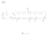
- Fig. 1 shows a perspective view of the support means 2, which essentially comprises a base body 4 and a connection element 5.
- connection element 5 serves to connect the connection device 1 to the control device or the electronics of a machine tool, charging device or accumulator, depending on whether the connection device 1 is contained in a machine tool, charging device or an accumulator.
- the connection element 5 can be connected to the control device or the electronics by means of a cable or a strand which is crimped, soldered or welded to the connection element 5. In the figures, neither the control device, electronics, the cable nor the wire is shown.
- the main body 4 of the carrier device 2 extends in an elongated shape and contains a first end 4a, a second end 4b, a bottom element 4c, a first side element 6 and a second side element 7.
- the main body 4 consists of an electrically conductive material.
- Both the first side member 6 and the second side member 7 each include a first side edge 6a, 7a and a second side edge 6b, 7b.
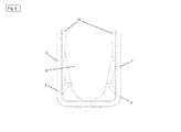
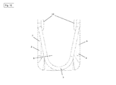
- the two side elements 6, 7 are each connected with their first side edges 6a, 7a to the bottom element 4c such that the base body 4 essentially forms the shape of a channel with a cavity 8.
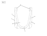
- the base body 4 has a U-shaped cross section. As described in detail later, the cavity 8 serves to receive the connection sockets 3.
- the base body 4 extends along the direction A or B.
- the first and second side elements 6, 7 have a number of recesses 9 on.
- five recesses 9 are provided according to a preferred embodiment.
- the recesses 9 extend substantially parallel to the longitudinal extent the side members 6, 7 and the support means 2.
- a number of retaining elements 10 is provided on the second side edge 6b of the first side member 6.
- five holding elements 10 are respectively positioned on the first side edge 6a of the first side element 6 and five holding elements 10 on the second side edge 6b of the first side element 6.
- the holding elements 10 of the first and second side member 6, 7 are bent to each other.
- the holding elements 10 are each cranked in the direction of the cavity 8 of the carrier device 2.
- the holding elements 10 serve to position and hold connection sockets 3 on the carrier device 2.
- the holding element 10 which is closest to the first end 4a of the base body 4, extends in the direction A.
- the remaining holding elements 10 extend in the direction B.
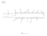
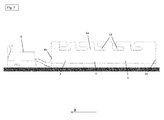
- the carrier device 2 of the connecting device 1 according to a second embodiment is shown.
- the connection device 1 according to the second embodiment is substantially identical to the connection device 1 according to the first embodiment.
- the holding elements 10 of the first and second side members 6, 7 according to the second embodiment are not bent or cranked to each other.
- the holding elements 10 of the first and second side elements 6, 7 extend straight to the side elements 6, 7 in the direction B or in the case of the holding element 10, which is the first end 4a of the base body 4 in the direction A
- the opposite holding elements 10, which are closest to the first end 4a of the base body 4 are bent or cranked relative to one another (cf. Fig. 6 or 8th ).
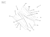
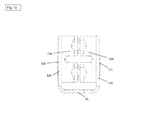
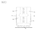
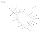
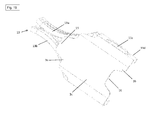
- connection socket 3 according to a first embodiment is shown.
- the female terminal 3 basically includes a first end 3a, a second end 3b, a bottom member 3c, a first wall member 11 second wall member 12 and a spring means 13.
- the first wall member 11 includes a front end 11 a, a rear end 11 b, a survey 11 c and a recess 11 d.
- the second wall member 12 also includes a front end 12a, a rear end 12b, a boss 12c, and a recess 12d.
- the spring device 13 in turn comprises a first spring element 13a and a second spring element 13b for receiving and holding an elongate contact element.
- the contact element is not shown in the figures.
- the first wall member 11 and the second wall member 12 are connected to the bottom member 3c and extend substantially orthogonal to the bottom member 3c. It should be noted that the first wall element 11 and the second wall element 12 can form a certain overextension. In other words, the two wall elements 11, 12 are not necessarily arranged at a right angle (90 °) to the bottom element 3c.
- the first wall element 11 extends at an obtuse angle (between 91 ° and 179 ° and preferably at 95 °) to the bottom element 3c in the direction C (see FIG. Fig. 14 ).
- the second wall element 12 extends at an obtuse angle (between 91 ° and 179 ° and preferably at 95 °) to the bottom element 3c in the direction C '(cf. Fig. 14 ).
- the overstretched arranged wall elements 11, 12 generate a certain tension or exert a certain pressure on the respective side elements 6, 7 of the carrier device 2 when the connection sockets 3 are arranged in the carrier device 2.
- the connection sockets 3 are clamped in the support means 2 and held against falling out too easily from the support means 2.
- the first elevation 11c is outside, i. Positioned in the direction of C on the first wall element 11 and the second elevation 12c is also outside, i. positioned in the direction C 'on the second wall element 12.
- the fact that the wall elements 11, 12 have a certain bias, the elevations 11c, 12c of the connection sockets 3 are always with the support means 2 for closing a circuit or for transmitting an electrical current from the contact element via the connection socket 3 to the carrier device 2.
- the recesses 11d, 12d on the respective wall elements 11, 12 are substantially rectangular in shape and serve to receive the holding elements 10, so that the connection sockets 3 are positioned and held by the holding elements 10 in the carrier device 2.
- the first and second wall elements 11, 12 and the bottom element 3c form a cavity 14 for receiving the elongated contact element.
- the base member 3 c at a first end a bulge 15 and at a second end a recess 16.
- the shape of the bulge 15 corresponds to the shape of the recess 16.
- the bulge 15 and the recess 16 are used for connection and positioning of the Connecting bushes 3 with each other on the support device 2.
- the bulge 15 engages a first connector 3 in the recess 16 of a second connector 3 (see. Fig. 25 and 26 ).
- the first spring member 13a extends in a curved shape from the rear end 11b of the first wall member 11 toward the front end 11a of the first wall member 11.
- the second spring member 13b extends in a curved shape from the rear end 12b of the second wall member 12 in the direction the front end 12a of the second wall member 12.
- the first and second spring members 13a, 13b can be reversibly moved from a first position to a second position.
- the two spring elements 13a, 13b are shown in the first position, wherein the two spring elements 13a, 13b touch with the aid of their spring force at the free ends.
- the two spring elements 13a, 13b are in the second position when the two spring elements 13a, 13b are moved away from each other against their spring force and in the direction of the respective wall elements 11, 12.
- the spring elements 13a, 13b in the second position are not shown in the figures.
- the spring elements 13a, 13b can be moved from the first to the second position to receive and hold the contact element by means of the spring force, when it is pushed between the spring elements 13a, 13b.
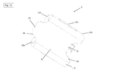
- connection socket 3 according to a second embodiment is shown.
- the female terminal 3 according to the second embodiment is substantially identical to the female terminal 3 according to the first embodiment.
- the first spring element 13a is arranged at the front end 11a of the first wall element 11 and extends in a curved shape in the direction B.
- the second spring element 13b is arranged at the front end 12a of the second wall element 12 and extends into bent shape in direction B.
- the spring elements 13a, 13b of the second embodiment can be reversibly moved from a first position to a second position to receive and hold a contact element.
- connection sockets 3 which are connected to the carrier device 2 and into which a contact element is inserted, depends on the capacity of the battery to be connected or on the maximum amount of current flowing between the connection device 1 and the contact element.
- a high number of connection sockets 3 offers a larger connection area for the contact element, so that a high current level can flow harmlessly or without possible damage to the connection device 1.
- the carrier device 2 in accordance with the number of connection sockets 3.
- a shorter carrier device 2 in particular a shorter main body
- the carrier device 2 or the base body 4 of the carrier device 2 to be extended if more than five connection sockets 3 are to be positioned on the carrier device 2.
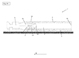
- Fig. 24 shows a connecting device 1 according to the first embodiment with a support means 2, in which the holding elements 10 are bent or cranked.
- a female terminal 3 according to the first embodiment is positioned in the main body 4 of the support 2.
- the connection socket 3 is arranged in the vicinity of the first end 4a of the main body 4.
- the connection socket 3 is positioned in the base body 4 of the carrier device 2 such that the holding elements 10 of the base body 4 of the carrier device 2 engage in the respective recesses 11d, 12d of the wall elements 11, 12 of the connection socket 3.
- the respective holding element 10 protrudes over the connection socket 3 (cf. Fig. 24 ) and against the connection socket 3 (cf. Fig. 27 ).
- connection socket 3 is positioned and held in the carrier device 2 such that the connection socket 3 neither in the direction A nor in the direction D from the carrier device 2 (see. Fig. 24 and 27 ) may fall out against the holding force of the holding element 10.
- the holding element 10 and the recess 11d, 12d of the connection socket 3 thus form a positive connection. Because of this positive connection, the connection sockets 3 need not be materially connected to the main body 4 of the support device 2. Because of the non-existing cohesive connection, the connection sockets 3 can be removed from the carrier device 2 again. This is particularly advantageous if during the Manufacturing process of the connecting device 1, one or more sockets 3 again taken from the carrier device 2 and / or to be replaced. A damaged connection socket 3 can be exchanged without having to dispose of a complete connection device 1, ie support device 2 with already positioned connection sockets 3. This saves time in the manufacturing process and reduces the potential waste.
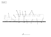
- Fig. 25 shows a connecting device 1 according to the first embodiment with a support means 2, in which the holding elements 10 are bent or cranked.
- Two female terminals 3 according to the first embodiment are positioned in the main body 4 of the carrier device 2.
- the two connection sockets 3 are positioned one behind the other in the direction B relative to one another.
- the two connection sockets 3 are positioned in the base body 4 of the carrier device 2 such that the holding elements 10 of the base body 4 of the carrier device 2 engage in the respective recesses 11 d, 12 d of the wall elements 11, 12 of the connection sockets 3.
- This means that the bulge 15 of a first connection socket 3 is arranged on the indentation 16 of a second connection socket 3.
- the connection sockets 3 are positioned and held in the carrier device 2 (cf. Fig. 25 ).
- Fig. 26 shows a connecting device 1 according to the first embodiment with a support means 2, in which the holding elements 10 are bent or cranked.
- Five connector sockets 3 according to the first embodiment are positioned in the main body 4 of the carrier device 2.
- the five connection sockets 3 are positioned in series one behind the other in the direction B to each other.
- the five connection sockets 3 are positioned in the base body 4 of the carrier device 2 such that the holding elements 10 of the base body 4 of the carrier device 2 engage in the respective recesses 11 d, 12 d of the wall elements 11, 12 of the connection sockets 3.
- This means that the bulges 15 of the connection sockets 3 are arranged on the indentations 16 of the adjacent connection socket 3.
- the connection sockets 3 are positioned and held in the carrier device 2 (cf. Fig. 26 ).
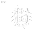
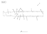
- Fig. 34 shows a connecting device 1 according to the first embodiment with a support means 2, in which the holding elements 10 are bent or cranked.
- a female terminal 3 according to the second embodiment is positioned in the main body 4 of the support 2.
- the connection socket 3 is arranged in the vicinity of the first end 4a of the main body 4.
- the connection socket 3 is positioned in the base body 4 of the carrier device 2 such that the holding elements 10 of the main body 4 of the Carrier device 2 in the respective recesses 11 d, 12 d of the wall elements 11, 12 of the connection socket 3 engage.
- the connection socket 3 is positioned and held in the carrier device 2 (see. Fig. 34 ).
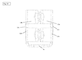
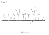
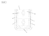
- Fig. 38 shows a connecting device 1 according to the first embodiment with a support means 2, in which the holding elements 10 are bent or cranked.
- Two female terminals 3 according to the second embodiment are positioned in the main body 4 of the carrier device 2.
- the two connection sockets 3 are positioned one behind the other in the direction B relative to one another.
- the two connection sockets 3 are positioned in the base body 4 of the carrier device 2 such that the holding elements 10 of the base body 4 of the carrier device 2 engage in the respective recesses 11 d, 12 d of the wall elements 11, 12 of the connection sockets 3.
- This means that the bulge 15 of a first connection socket 3 is arranged on the indentation 16 of a second connection socket 3.
- the connection sockets 3 are positioned and held in the carrier device 2 (cf. Fig. 38 ).
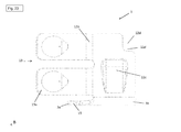
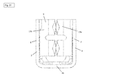
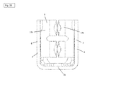
- Fig. 39 shows a connecting device 1 according to the first embodiment with a support means 2, in which the holding elements 10 are bent or cranked.
- Five connector sockets 3 according to the second embodiment are positioned in the main body 4 of the carrier device 2.
- the five connection sockets 3 are positioned in series one behind the other in the direction B to each other.
- the five connection sockets 3 are positioned in the base body 4 of the carrier device 2 such that the holding elements 10 of the base body 4 of the carrier device 2 engage in the respective recesses 11 d, 12 d of the wall elements 11, 12 of the connection sockets 3.
- This means that the bulges 15 of the connection sockets 3 are arranged on the indentations 16 of the adjacent connection socket 3.
- the connection sockets 3 are positioned and held in the carrier device 2 (cf. Fig. 39 ).
- Fig. 40 shows a connecting device 1 according to the second embodiment with a support means 2, in which the holding elements 10 are straight.
- a female terminal 3 according to the first embodiment is positioned in the main body 4 of the support 2.
- the connection socket 3 is arranged in the vicinity of the first end 4a of the main body 4.
- the connection socket 3 is positioned in the base body 4 of the carrier device 2 such that the holding elements 10 of the base body 4 of the carrier device 2 engage in the respective recesses 11d, 12d of the wall elements 11, 12 of the connection socket 3.
- the connection socket 3 is positioned and held in the carrier device 2 (see. Fig. 35 and 36 ).
- Fig. 42 shows a connecting device 1 according to the second embodiment with a support means 2, in which the holding elements 10 are straight.
- Two female terminals 3 according to the first embodiment are positioned in the main body 4 of the carrier device 2.
- the two connection sockets 3 are positioned one behind the other in the direction B relative to one another.
- the two connection sockets 3 are positioned in the base body 4 of the carrier device 2 such that the holding elements 10 of the base body 4 of the carrier device 2 engage in the respective recesses 11 d, 12 d of the wall elements 11, 12 of the connection sockets 3.
- This means that the bulge 15 of a first connection socket 3 is arranged on the indentation 16 of a second connection socket 3.
- the connection sockets 3 are positioned and held in the carrier device 2 (cf. Fig. 42 ).
- Fig. 43 shows a connecting device 1 according to the second embodiment with a support means 2, in which the holding elements 10 are straight.
- Five connector sockets 3 according to the first embodiment are positioned in the main body 4 of the carrier device 2.
- the five connection sockets 3 are positioned in series one behind the other in the direction B to each other.
- the five connection sockets 3 are positioned in the base body 4 of the carrier device 2 such that the holding elements 10 of the base body 4 of the carrier device 2 engage in the respective recesses 11 d, 12 d of the wall elements 11, 12 of the connection sockets 3.
- This means that the bulges 15 of the connection sockets 3 are arranged on the indentations 16 of the adjacent connection socket 3.
- the connection sockets 3 are positioned and held in the carrier device 2 (cf. Fig. 43 ).
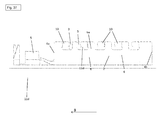
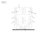
- Fig. 46 shows a connecting device 1 according to the second embodiment with a support means 2, in which the holding elements 10 are straight.
- a female terminal 3 according to the second embodiment is positioned in the main body 4 of the support 2.
- the connection socket 3 is arranged in the vicinity of the first end 4a of the main body 4.
- the connection socket 3 is positioned in the base body 4 of the carrier device 2 such that the holding elements 10 of the base body 4 of the carrier device 2 engage in the respective recesses 11d, 12d of the wall elements 11, 12 of the connection socket 3.
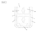
- the connection socket 3 is positioned and held in the carrier device 2 (see. Fig. 46 ).
- Fig. 49 shows a connecting device 1 according to the second embodiment with a support means 2, in which the holding elements 10 are straight.
- Two connector sockets 3 according to the second embodiment are in the main body 4 of the carrier device 2 positioned.
- the two connection sockets 3 are positioned one behind the other in the direction B relative to one another.
- the two connection sockets 3 are positioned in the base body 4 of the carrier device 2 such that the holding elements 10 of the base body 4 of the carrier device 2 engage in the respective recesses 11 d, 12 d of the wall elements 11, 12 of the connection sockets 3.
- This means that the bulge 15 of a first connection socket 3 is arranged on the indentation 16 of a second connection socket 3.
- the connection sockets 3 are positioned and held in the carrier device 2 (cf. Fig. 49 ).
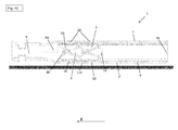
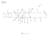
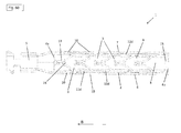
- Fig. 50 shows a connecting device 1 according to the second embodiment with a support means 2, in which the holding elements 10 are straight.
- Five connector sockets 3 according to the second embodiment are positioned in the main body 4 of the carrier device 2.
- the five connection sockets 3 are positioned in series one behind the other in the direction B to each other.
- the five connection sockets 3 are positioned in the base body 4 of the carrier device 2 such that the holding elements 10 of the base body 4 of the carrier device 2 engage in the respective recesses 11 d, 12 d of the wall elements 11, 12 of the connection sockets 3.
- This means that the bulges 15 of the connection sockets 3 are arranged on the indentations 16 of the adjacent connection socket 3.
- the connection sockets 3 are positioned and held in the carrier device 2 (cf. Fig. 50 ).
- connection sockets 3 according to the first embodiment are non-positively or positively connected to the carrier device 2 according to the first embodiment. In other words, the connection sockets 3 are clamped between the respective holding elements 10 and held by them in position. The connection between connection sockets 3 and the carrier device 2 according to the first embodiment is thus detachable again.
- connection sockets 3 according to the second embodiment are integrally connected to the carrier device 2 according to the second embodiment.
- cohesive connections include, for example, welding, soldering, gluing or the like.
- a connecting device 1 for releasably connecting electrical connections for example between an accumulator and an electric machine tool or a rechargeable battery and a charging device, with which in particular an improved, i. can be used modularly and in their production more flexible, connecting device 1 is provided.
Landscapes
- Details Of Connecting Devices For Male And Female Coupling (AREA)
- Connector Housings Or Holding Contact Members (AREA)
Priority Applications (5)
| Application Number | Priority Date | Filing Date | Title |
|---|---|---|---|
| EP15157962.0A EP3065227A1 (fr) | 2015-03-06 | 2015-03-06 | Prise multiple sur rails |
| CN201680003754.XA CN107004988A (zh) | 2015-03-06 | 2016-03-04 | 轨道式复接插头 |
| EP16708976.2A EP3266071B1 (fr) | 2015-03-06 | 2016-03-04 | Dispositif de connexion |
| PCT/EP2016/054644 WO2016142286A1 (fr) | 2015-03-06 | 2016-03-04 | Connecteur multiple sur rail |
| US15/544,139 US10205262B2 (en) | 2015-03-06 | 2016-03-04 | Multi-contact plug on rail |
Applications Claiming Priority (1)
| Application Number | Priority Date | Filing Date | Title |
|---|---|---|---|
| EP15157962.0A EP3065227A1 (fr) | 2015-03-06 | 2015-03-06 | Prise multiple sur rails |
Publications (1)
| Publication Number | Publication Date |
|---|---|
| EP3065227A1 true EP3065227A1 (fr) | 2016-09-07 |
Family
ID=52598677
Family Applications (2)
| Application Number | Title | Priority Date | Filing Date |
|---|---|---|---|
| EP15157962.0A Withdrawn EP3065227A1 (fr) | 2015-03-06 | 2015-03-06 | Prise multiple sur rails |
| EP16708976.2A Active EP3266071B1 (fr) | 2015-03-06 | 2016-03-04 | Dispositif de connexion |
Family Applications After (1)
| Application Number | Title | Priority Date | Filing Date |
|---|---|---|---|
| EP16708976.2A Active EP3266071B1 (fr) | 2015-03-06 | 2016-03-04 | Dispositif de connexion |
Country Status (4)
| Country | Link |
|---|---|
| US (1) | US10205262B2 (fr) |
| EP (2) | EP3065227A1 (fr) |
| CN (1) | CN107004988A (fr) |
| WO (1) | WO2016142286A1 (fr) |
Cited By (1)
| Publication number | Priority date | Publication date | Assignee | Title |
|---|---|---|---|---|
| CN112217023A (zh) * | 2019-07-12 | 2021-01-12 | 菲尼克斯电气公司 | 用于插接连接器的触点载体 |
Families Citing this family (1)
| Publication number | Priority date | Publication date | Assignee | Title |
|---|---|---|---|---|
| EP3444905A1 (fr) * | 2017-08-18 | 2019-02-20 | HILTI Aktiengesellschaft | Raccord à emboîtement pour une unité d'accumulateur |
Citations (5)
| Publication number | Priority date | Publication date | Assignee | Title |
|---|---|---|---|---|
| JPS518453Y1 (fr) * | 1970-12-18 | 1976-03-06 | ||
| DE3014118B1 (de) * | 1980-03-13 | 1981-02-26 | Sotax Ag | Kontaktorgan |
| US20100151748A1 (en) * | 2008-12-15 | 2010-06-17 | Yazaki Corporation | Terminal |
| EP2451016A1 (fr) * | 2009-07-03 | 2012-05-09 | Yazaki Corporation | Borne femelle |
| US20120156947A1 (en) * | 2010-12-17 | 2012-06-21 | Tyco Electronics Corporation | Receptacle terminal |
Family Cites Families (14)
| Publication number | Priority date | Publication date | Assignee | Title |
|---|---|---|---|---|
| US3183471A (en) * | 1963-02-08 | 1965-05-11 | Thomas & Betts Corp | Electrical terminal and connection |
| JPS518453A (en) | 1974-07-10 | 1976-01-23 | Hideaki Sakurai | Hanryokuo ryoshita hantenkudosochi |
| DE2527681C3 (de) * | 1975-06-21 | 1978-05-24 | Multi-Contact Ag, Allschwil (Schweiz) | Elektrische Kontaktanordnung |
| US5588884A (en) * | 1995-09-08 | 1996-12-31 | Packard Hughes Interconnect Company | Stamped and formed contacts for a power connector |
| JP3698296B2 (ja) * | 1999-08-19 | 2005-09-21 | 株式会社マキタ | 端子構造 |
| US6312276B1 (en) * | 2001-01-17 | 2001-11-06 | Fullcom Technology Corp. | Terminals for achieving preferred electric and mechanic connection |
| US20030060090A1 (en) * | 2001-09-21 | 2003-03-27 | Allgood Christopher L. | High current automotive electrical connector and terminal |
| DE202011003555U1 (de) * | 2011-03-04 | 2011-05-26 | ROSENBERGER Hochfrequenztechnik GmbH & Co. KG, 83413 | Hochstromsteckverbinder mit Ringfederkontaktierung |
| US8690609B2 (en) * | 2011-06-09 | 2014-04-08 | Bal Seal Engineering, Inc. | Method, apparatus and system for positioning and holding electrical contacts, seals and related components |
| DE102011112120B4 (de) * | 2011-09-02 | 2018-04-05 | Phoenix Contact Gmbh & Co. Kg | Vorrichtung mit mehreren Blockklemmen |
| US8888537B2 (en) * | 2012-11-16 | 2014-11-18 | Apple Inc. | Audio jack with multiple points of contact |
| JP6091968B2 (ja) * | 2013-04-04 | 2017-03-08 | 株式会社マキタ | 電動工具用電池パック |
| JP6215088B2 (ja) * | 2014-03-03 | 2017-10-18 | 株式会社マキタ | 電動工具用電池パック |
| JP6480782B2 (ja) * | 2015-04-02 | 2019-03-13 | 株式会社マキタ | 電気機器 |
-
2015
- 2015-03-06 EP EP15157962.0A patent/EP3065227A1/fr not_active Withdrawn
-
2016
- 2016-03-04 EP EP16708976.2A patent/EP3266071B1/fr active Active
- 2016-03-04 US US15/544,139 patent/US10205262B2/en active Active
- 2016-03-04 WO PCT/EP2016/054644 patent/WO2016142286A1/fr not_active Ceased
- 2016-03-04 CN CN201680003754.XA patent/CN107004988A/zh active Pending
Patent Citations (5)
| Publication number | Priority date | Publication date | Assignee | Title |
|---|---|---|---|---|
| JPS518453Y1 (fr) * | 1970-12-18 | 1976-03-06 | ||
| DE3014118B1 (de) * | 1980-03-13 | 1981-02-26 | Sotax Ag | Kontaktorgan |
| US20100151748A1 (en) * | 2008-12-15 | 2010-06-17 | Yazaki Corporation | Terminal |
| EP2451016A1 (fr) * | 2009-07-03 | 2012-05-09 | Yazaki Corporation | Borne femelle |
| US20120156947A1 (en) * | 2010-12-17 | 2012-06-21 | Tyco Electronics Corporation | Receptacle terminal |
Cited By (2)
| Publication number | Priority date | Publication date | Assignee | Title |
|---|---|---|---|---|
| CN112217023A (zh) * | 2019-07-12 | 2021-01-12 | 菲尼克斯电气公司 | 用于插接连接器的触点载体 |
| CN112217023B (zh) * | 2019-07-12 | 2022-08-16 | 菲尼克斯电气公司 | 用于插接连接器的触点载体 |
Also Published As
| Publication number | Publication date |
|---|---|
| EP3266071B1 (fr) | 2021-09-01 |
| EP3266071A1 (fr) | 2018-01-10 |
| CN107004988A (zh) | 2017-08-01 |
| WO2016142286A1 (fr) | 2016-09-15 |
| US20180006392A1 (en) | 2018-01-04 |
| US10205262B2 (en) | 2019-02-12 |
Similar Documents
| Publication | Publication Date | Title |
|---|---|---|
| EP3031103B1 (fr) | Système comprenant une pluralité de modules de connecteur électrique et un cadre de support électriquement conducteur | |
| DE102010042056B4 (de) | Elektrische Anschlussklemme | |
| DE102011078412B4 (de) | Elektrischer Anschluss zum Aufnehmen eines Steckers | |
| EP3316402A1 (fr) | Douille de contact plate | |
| DE102013013458B3 (de) | Kontaktelement | |
| DE112017003846T5 (de) | Leistungsanschluss für einen elektrischen Verbinder | |
| DE112013005056T5 (de) | Elektrischer Anschluss | |
| DE112017001463T5 (de) | Anschlussmodul | |
| DE10351513B4 (de) | Buchsenklemme und elektrischer Verbinder mit derartigen Buchsenklemmen | |
| DE102014000955B4 (de) | Verbinder mit einer elektronischen Komponente, Halteeinrichtung und Herstellungsverfahren | |
| DE102016206846B4 (de) | Verbindungseinrichtung, Hochvoltbatterie und Kraftfahrzeug | |
| EP3266071B1 (fr) | Dispositif de connexion | |
| DE10040893B4 (de) | Struktur von elektrischen Anschlüssen zum Herstellen eines elektrischen Kontakts zwischen einem Batterieteil und einer elektrischen Vorrichtung | |
| DE2044506B2 (de) | Elektrische steckbuchse | |
| DE202009018505U1 (de) | Akkumulatoreinheit und tragbares elektronisches Gerät | |
| DE202010009293U1 (de) | Reihenklemme | |
| DE102013225340A1 (de) | Batteriemodul mit einer Mehrzahl von Batteriezellen sowie Batteriesystem mit wenigstens einem solchen Batteriemodul | |
| DE102005037864A1 (de) | Ladesteckverbinder | |
| DE102013018890A1 (de) | Anschlussleiste und Federklemmadapter | |
| EP2936617A1 (fr) | Chambre de raccordement multiple à barre omnibus | |
| DE102017223225A1 (de) | Verfahren zur Herstellung einer Verbindung zwischen einem Leiter und einem elektrischen Kontakt eines Batteriemoduls sowie Batteriemodul | |
| DE212024000142U1 (de) | Zweireihige PIN-Anordnung eines Batteriepacks | |
| EP3665746A1 (fr) | Accouplement par enfichage pour unité de batterie | |
| WO2024052014A1 (fr) | Agencement pour charger des lunettes de données, ainsi que lunettes de données et dispositif de charge | |
| EP1336229A1 (fr) | Dispositif de chargement |
Legal Events
| Date | Code | Title | Description |
|---|---|---|---|
| PUAI | Public reference made under article 153(3) epc to a published international application that has entered the european phase |
Free format text: ORIGINAL CODE: 0009012 |
|
| AK | Designated contracting states |
Kind code of ref document: A1 Designated state(s): AL AT BE BG CH CY CZ DE DK EE ES FI FR GB GR HR HU IE IS IT LI LT LU LV MC MK MT NL NO PL PT RO RS SE SI SK SM TR |
|
| AX | Request for extension of the european patent |
Extension state: BA ME |
|
| STAA | Information on the status of an ep patent application or granted ep patent |
Free format text: STATUS: THE APPLICATION IS DEEMED TO BE WITHDRAWN |
|
| 18D | Application deemed to be withdrawn |
Effective date: 20170308 |