EP3065267A1 - Âmes pour machines électriques - Google Patents
Âmes pour machines électriques Download PDFInfo
- Publication number
- EP3065267A1 EP3065267A1 EP16158924.7A EP16158924A EP3065267A1 EP 3065267 A1 EP3065267 A1 EP 3065267A1 EP 16158924 A EP16158924 A EP 16158924A EP 3065267 A1 EP3065267 A1 EP 3065267A1
- Authority
- EP
- European Patent Office
- Prior art keywords
- segment
- core
- notch
- recited
- segments
- Prior art date
- Legal status (The legal status is an assumption and is not a legal conclusion. Google has not performed a legal analysis and makes no representation as to the accuracy of the status listed.)
- Granted
Links
Images

Classifications
-
- H—ELECTRICITY
- H02—GENERATION; CONVERSION OR DISTRIBUTION OF ELECTRIC POWER
- H02K—DYNAMO-ELECTRIC MACHINES
- H02K1/00—Details of the magnetic circuit
- H02K1/06—Details of the magnetic circuit characterised by the shape, form or construction
- H02K1/22—Rotating parts of the magnetic circuit
- H02K1/26—Rotor cores with slots for windings
- H02K1/265—Shape, form or location of the slots
-
- H—ELECTRICITY
- H02—GENERATION; CONVERSION OR DISTRIBUTION OF ELECTRIC POWER
- H02K—DYNAMO-ELECTRIC MACHINES
- H02K1/00—Details of the magnetic circuit
- H02K1/06—Details of the magnetic circuit characterised by the shape, form or construction
- H02K1/22—Rotating parts of the magnetic circuit
- H02K1/24—Rotor cores with salient poles ; Variable reluctance rotors
-
- H—ELECTRICITY
- H02—GENERATION; CONVERSION OR DISTRIBUTION OF ELECTRIC POWER
- H02K—DYNAMO-ELECTRIC MACHINES
- H02K3/00—Details of windings
- H02K3/04—Windings characterised by the conductor shape, form or construction, e.g. with bar conductors
- H02K3/18—Windings for salient poles
- H02K3/20—Windings for salient poles for auxiliary purposes, e.g. damping or commutating
-
- H—ELECTRICITY
- H02—GENERATION; CONVERSION OR DISTRIBUTION OF ELECTRIC POWER
- H02K—DYNAMO-ELECTRIC MACHINES
- H02K2213/00—Specific aspects, not otherwise provided for and not covered by codes H02K2201/00 - H02K2211/00
- H02K2213/03—Machines characterised by numerical values, ranges, mathematical expressions or similar information
Definitions
- the present disclosure relates to electrical machines, and more particularly to cores for synchronous machine motors and generators.
- Electrical machines like motors, generators, and starter/generators commonly include a rotor and a stator.
- the rotor is typically supported for rotation relative to the stator such that, in motor arrangements, electrical power applied to stator produces a magnetic field that interacts with the rotor and causes the rotor to rotate and thereby provide a source of rotational energy.
- rotational energy applied to the rotor causes a magnetic field produced by the rotor to move relative to windings disposed on the stator, induces current flow through the stator windings and produces electrical power suitable for harvest from the generator.
- electrical machines like motor/generators include amortisseur bars disposed on the rotor that are electrically connected (e.g.
- the amortisseur bars can dampen torsional oscillations imposed on the rotor by electrical load fluctuations.
- current applied to the amortisseur bars produce a magnetic field that interacts with a magnetic field produced by the stator windings, thereby rotating the rotor and producing rotational energy.
- heating of rotor can induce geometry change that creates stress on the rotor, which must be managed for reliable operation.
- a core for an electrical machine includes a core body extending along a rotation axis.
- the core body includes a first segment and a plurality of second segments axially stacked with one another along the rotation axis.
- the first and the second segments both define notches that are axially aligned with one another to form a slot.
- the notches of the second segments have areas that are each greater than an area of the first segment notch to accommodate thermal expansion of the core.
- the first and second segments can include cobalt or a cobalt-containing alloy.
- the first and second segments can have plate-like bodies with peripheries extending about the rotation axis.
- the peripheries can be radially inner peripheries, and the first segment can be axially aligned with the second segment such that the inner peripheries of the first and second segments define a central aperture of the core body.
- the central aperture can seat a shaft, thereby enabling connection of the core to a prime mover.
- the peripheries can also be radially outer peripheries, and the notches of the first and second segment can be defined in the radially outer peripheries of the first and second segment plate-like bodies.
- the periphery of the first segment plate-like body can define an opening into the first segment notch.
- the opening can be smaller than a width of an interior of the first segment notch.
- Circumferentially adjacent teeth can bound the opening, and the width opening can be smaller than a width of a damper bar seated within the first segment notch.
- the first segment can be coupled to the second segment such that the first and second segments are axially stacked with one another the rotation axis, such as with a resin or other adhesive, for forming a laminated core body.
- An end segment formed from a material with a greater coefficient of thermal expansion than that of the first and second segments can be coupled to the second segment on a side opposite the first segment.
- the periphery of the second segment plate-like body can define an opening into the second segment notch.
- the opening can be as wide or wider than an interior width of the second segment notch at the widest point of the notch interior.
- the opening can be also be wider than the width of the damper bar seated within the slot defined by the notches of the first and second segments.
- the opening into the second segment notch can be greater than the first segment notch opening, the damper bar thereby being less constrained radially by the first segment than by the second segment of the core body.
- the damper bar can seat within the slot such that the damper bar is less radially constrained by the second segment than by the first segment, thereby allowing the damper bar to deflect away from the core body by progressively larger amounts in closer to the end plate. It is further contemplated that braze can fix the damper bar in the first segment, thereby radially restraining the damper bar and imposing shear stress on the first segment in a region bounding the first segment notch.
- a rotor for a synchronous machine includes a shaft and a core body as described above seated on the shaft.
- a damper bar seated in the slot is radially unconstrained by the second segment, and is radially constrained by both the end segment and the first segment.
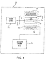
- FIG. 1 a partial view of an exemplary embodiment of an electrical machine in accordance with the disclosure is shown in Fig. 1 and is designated generally by reference character 10.
- FIG. 2-8 Other embodiments of electrical machines in accordance with the disclosure, or aspects thereof, are provided in Figs. 2-8 , as will be described.
- the systems and methods described herein can be used for aircraft electrical systems, such as in synchronous machine generators for producing electrical power and/or synchronous machine motors for converting electrical power into mechanical rotational energy.
- Exemplary electrical machine 10 includes a stator 12 with stator windings 14 and a rotor 16 carrying field coils 18.
- Stator windings 14 are fixed to stator 12 and are electrically connected to an aircraft power bus 20.
- Rotor 16 includes a core 100 carrying field coils 18 and is operatively coupled to a prime mover 22 by a shaft 24.
- prime mover 22 is a gas turbine engine or internal combustion engine.
- Electrical machine 10 may be a generator, a motor, or a starter/generator operatively associated with prime mover 22 for supplying power to power-consuming devices disposed on an aircraft.
- prime mover 22 is an aircraft main engine or auxiliary power unit for an aircraft.
- Electrical machine 10 may have a generate mode.
- prime mover 22 rotates rotor 16 by applying rotational energy to shaft 24.
- Shaft 24 applies the received rotational energy to rotor 16, thereby rotating rotor 16 about a rotation axis R and moving a magnetic field produced by field coils 18 relative to stator windings 14. Movement of the magnetic field induces a current flow within stator windings 14 which electrical machine 10 provides to aircraft power bus 20.
- Aircraft power bus 20 converts the received current into power suitable for one or more power-consuming devices (not shown for clarity purposes) coupled to aircraft power bus 20.
- Electrical machine 10 may have a motor mode.
- stator windings 14 receive current from aircraft power bus 20.
- the current flow produces a magnetic field that is fixed relative to rotor 16 and which interacts with a magnetic field produced by field coils 18.
- Interaction of the magnetic fields rotates rotor 16 about rotation axis R, provides rotational energy to prime mover 22, and enables starting prime mover 22 for purposes of autonomous operation thereafter.
- electrical machine 10 has both motor and generate modes. This enables electrical machine 10 to operate as a motor in motor mode, provide rotational energy to prime mover 22 for starting prime mover 22, switch to generate mode, and thereafter receive rotational energy from prime mover 22 for purposes of generating electrical power.
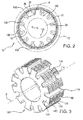
- Electrical machine 10 includes stator 12 and rotor 16.
- Rotor 16 is rotateably supported about rotation axis R in relation to stator 12 by shaft 24 and includes core 100.
- Core 100 includes a core body 102 with a radially inner periphery 104 and a radially outer periphery 106, shaft 24, field coils 18, and damper bars 30.
- Radially inner periphery 104 defines a central aperture within which shaft 24 is seated.
- Radially outer periphery 106 defines a plurality of rotor poles 108. Circumferentially adjacent rotor poles 108 define circumferentially between one another field coil slots. Rotor field coils 18 seat within each of the field coil slots. Respective rotor poles 108 define a pole face 110 (indicated in Fig. 3 ) that faces stator 12 across a radial gap defined between stator 12 and rotor 16.
- electrical machine 10 is a brushless, wound field synchronous generator that may be operated as a motor in a starting mode to convert electrical power supplied by an external AC power source into motive power or, alternatively, in a generate mode to convert mechanical energy into electrical power.
- the starter generator is one assembly of an overall generator assembly, which may include a permanent magnet generator (PMG), an exciter generator for brushless operation and a main generator mounted on a common shaft.
- PMG permanent magnet generator
- exciter generator for brushless operation
- main generator mounted on a common shaft.
- pole faces 110 of rotor poles 108 define axially extending slots 114.
- Each slot 114 seats a damper bar (Amortisseur bar) 30 that extends axially along a length of core body 102 and across the respective pole face 110 defining slot 114.
- Damper bars 30 are electrically connected to one another through end segments 116 to form a damping circuit (Amortisseur circuit), or damping winding.
- the damping circuit is operative to dampen torsional oscillation associated with electrical load variation and/or provide electromotive force for rotating rotor 16, dependent upon the operating mode(s) of electrical machine 10.
- Damper bars 30 include a paramagnetic or soft ferromagnetic material.
- a “paramagnetic material” is a material which is slightly magnetically attracted when in the presence of an externally applied magnetic field, and may have a relative magnetic permeability greater or equal to unity (i.e., a positive magnetic susceptibility) and hence is attracted to magnetic fields.
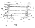
- Core body 102 includes end segments 116, at least one first segment 120, and a plurality of second segments 140.
- First segment 120 is axially stacked with the plurality of second segments 140 and end segments 116 along rotation axis R.
- First segment 120 is coupled to the plurality of second segments 140 by a resin or laminate.
- End segments 116 are mechanically coupled to second segments 140 at opposite ends of the laminated structure by damper bars 30.
- Damper bars 30 are fixed to end segments 116 by a brazed joint or other suitable fastening arrangement.
- End segments 116 include a material with a greater coefficient of thermal expansion than a material included in first segment 120 and/or the plurality of second segments 140.
- first segment 120 and/or the plurality of second segments 140 include a cobalt-containing alloy, such as a cobalt-iron-vanadium alloy.
- End segments 116 may include a conductive material, such as aluminum, copper, or other material for an intended application.
- One challenge with some kinds of conventional electrical machines is that the rotor core body is exposed to heat during operation, such as from resistive heating in stator windings 14 (shown in Fig. 1 ) and/or rotor field coils 18 (shown in Fig. 2 ). Heating can also result from windage, i.e. heat generated by the friction of rotor poles passing through an oil or cooling fluid. Since end segments 116 include a material with a greater coefficient of thermal expansion than first segment 120 and/or the plurality of second segments 140, heating can cause end segments 116 to expand at a greater rate than first segment 120 and the plurality of second segments 140.
- heating can cause portions of damper bars proximate to end segments to displace radially further than portions of damper bars further away from the end segments, loading the core body and imposing stress on portions of the segments radially restraining the damper bar or the damper bars themselves.
- the stress can be sufficient to fracture the core body or the damper bars themselves.
- shear stress imposed on the core structure bounding the damper bar slot by radial deflection of the damper bar which, due to differences between their respective coefficients of thermal expansion, can be sufficient to fracture the portion of the core structure radially restraining the damper bar unless the rotor temperature is maintained below a predetermined limit.
- Second segment 140 is axially stacked between first segment 120 and end segment 116 such that a second segment notch 148 is axially aligned with a first segment notch 128, thereby forming slot 114.
- Slot 114 is configured to seat damper bar 30 (shown in Fig. 2 ) such that damper bar 30 extends axially along the length of core body 102 between opposed end segments 116.
- second segment notch 148 has a greater area and/or a wider circumferential opening that first segment notch 128, allowing damper bar 30 to deflect away from core body 102 (i.e.
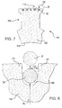
- First segment 120 includes a plate-like body 122 constructed from a cobalt-containing material.
- Plate-like body 122 extends radially between a first segment inner periphery 124 and a first segment outer periphery 126, and is coupled to second segment 140 (shown in Fig. 4 ) such that the inner peripheries of the first and second segments both define portions of inner periphery 104 (shown in Fig. 2 ) and the outer peripheries of the first and second segments both define portion of radially outer periphery 106 (shown in Fig. 2 ).
- First segment outer periphery 126 defines first segment notch 128.
- First segment notch 128 is aligned with second segment notch 148 (shown in Fig. 4 ) to form slot 114 (shown in Fig. 4 ).
- Damper bar 30 seats within first segment notch 128.
- Plate-like body 122 includes a pair of circumferentially-opposed notch teeth 121.
- Circumferentially opposed notch teeth 121 bound a portion first segment notch 128 and define therebetween an opening 123 into first segment notch 128.
- Opening 123 has a width that is smaller than a width of damper bar 30, radially constraining damper bar 30 such that radially outward forces, e.g. force F 1 , urge a radially outer surface damper bar 30 against interior surfaces of teeth 121.
- the force loads plate-like body 122, and impose stresses upon the material forming teeth 121.
- stress above a predetermined limit can exceed the ultimate stress of the material forming first segment 120, fracturing plate-like body 122 and potentially causing portion(s) of teeth 121 to separate from plate-like body 122.
- Force F 1 results from the differential in radial growth between first segment 120 and end segment 116.
- the differential in radial growth results from the difference between the coefficient of thermal expansion of the material forming end segment 116 relative to the coefficient of thermal expansion of the material forming first segment 120. This causes end segment 116 to drive damper bar 30 radially outward, causing F 1 , and giving rise to opposing force F 2 which is equal and opposite to force F 1 .
- force F 2 imposes stress within first segment 120.
- Second segment 140 includes a plate-like body 142.
- Plate-like body 142 is constructed from a cobalt-containing material, such as a cobalt-iron-vanadium alloy or other suitable cobalt alloy, and extends radially between an inner periphery 144 and an outer periphery 146.
- Inner periphery 144 aligns axially with first segment inner periphery 124 (shown in Fig. 5 ) to collectively form therewith core inner periphery 104 (shown in Fig.
- outer periphery 146 aligns axially with first segment outer periphery 126 (shown in Fig. 5 ) to collectively form therewith core outer periphery 106 (shown in Fig. 2 ).
- second segment 140 and first segment 120 form axially stacked segments of a laminated core body for an electrical machine.
- Second segment notch 148 is defined by outer periphery 146 within pole face 110. Second segment notch 148 is aligned with first segment notch 128 (shown in Fig. 5 ), collectively forming portions slot 114 (shown in Fig. 4 ). Damper bar 30 seats within second segment notch 148.
- second segment plate-like body 142 includes a pair of circumferentially opposed faces 141. This can provide a second segment notch 148 is greater than a notch area of first segment notch 128, allowing for residual resin associated with lamination of second segment 140 to first segment 120 to deposit within second segment notch 148 without fixing damper bar 30 to plate-like body 142 within second segment notch 148.
- Circumferentially opposed faces 141 bound a portion second segment notch 148 and define therebetween an opening 143 into second segment notch 148. Opening 143 has a width that is greater than the width of damper bar 30.
- damper bar 30 to seat within second segment notch 148 such that it is less constrained by second segment 140 than by first segment 120 (shown in Fig. 5 ).
- damper bar 30 be substantially unconstrained by second segment 140. Radially unconstrained, damper bar 30 can radially displace in response to displacement imposed by thermal expansion of end segment 116 (shown in Fig. 4 ), e.g. displacement D 1 , between first and second positons.
- end segment 116 shown in Fig. 4
- displacement D 1 between first and second positons.
- one or more second segments 140 can be axially stacked with one another between first segment 120 and end segment 116, as suitable for a given application, such as at axial locations where F 2 would impose stress above the yield stress of the material forming the segment under operating conditions.
- Some electrical machines rotors include cores formed from material with different coefficients of expansion.
- some electrical machines include cobalt alloy (e.g. a cobalt-iron-vanadium alloy) and end segments including copper at axially opposite ends of the rotor.
- the copper end laminations are typically brazed to damping bars that run the axial length of the core.
- the damping bar cannot be radially constrained by the cobalt alloy because copper tends to expand significantly more than the cobalt alloy for a given temperature change.
- copper has a coefficient of thermal expansion (CTE) of about 9.2 x 10 -6 to 9.8 x 10 -6 in/°F
- cobalt alloys can have a CTE of about 4.96 x 10 -6 to 5.24 x 10 -6 in/°F, or a CTE difference of about 3.96 x 10 -6 to 4.84 x 10 -6 in/°F. Due to the CTE difference of the materials, the end segments therefore tend to expand more rapidly than the interior segments. This causes the damper bars to deflect radially outward progressively, outer segments of the core therefore generally experiencing greater loadings and stress than interior segments of the core.
- CTE coefficient of thermal expansion
- first segment 120 may experience smaller amounts of damper bar deflection than second segment 140.
- Providing relatively wide notch openings on second segment 140 can reduce the loading and associated stress on second segment 140 by allowing the damper bar to deflect freely from second segment 140.
- the relatively large area of the outer segments can also alleviate the problem of braze filling the gap between second segment 140 and the damper bar by providing space for the material to deposit without bonding the damper bar to second segment 140.
- a plurality of second segments 140 are axially stacked between end segment 116 and first segment 120. This can provide sufficient radial freedom for deflection of the damper bar at an axial end of the core to prevent fracturing teeth that radially constrain the damper bar within the damper bar slot while allowing one or more first segments 120 disposed axially inward of the core to radially restrain the damper bars.
- any number of segments can have widened notches, as suitable for a given application of the core body.
Landscapes
- Engineering & Computer Science (AREA)
- Power Engineering (AREA)
- Iron Core Of Rotating Electric Machines (AREA)
Applications Claiming Priority (1)
| Application Number | Priority Date | Filing Date | Title |
|---|---|---|---|
| US14/640,767 US9698635B2 (en) | 2015-03-06 | 2015-03-06 | Cores for electrical machines |
Publications (2)
| Publication Number | Publication Date |
|---|---|
| EP3065267A1 true EP3065267A1 (fr) | 2016-09-07 |
| EP3065267B1 EP3065267B1 (fr) | 2020-07-15 |
Family
ID=55484906
Family Applications (1)
| Application Number | Title | Priority Date | Filing Date |
|---|---|---|---|
| EP16158924.7A Active EP3065267B1 (fr) | 2015-03-06 | 2016-03-07 | Âmes pour machines électriques |
Country Status (2)
| Country | Link |
|---|---|
| US (1) | US9698635B2 (fr) |
| EP (1) | EP3065267B1 (fr) |
Cited By (2)
| Publication number | Priority date | Publication date | Assignee | Title |
|---|---|---|---|---|
| EP3382863A1 (fr) * | 2017-03-30 | 2018-10-03 | ABB Schweiz AG | Procédé permettant de détecter un défaut de barre de rotor |
| EP3567706A1 (fr) * | 2018-05-10 | 2019-11-13 | Ge Aviation Systems Llc, Inc. | Ensembles formés par fabrication additive pour machines électriques |
Families Citing this family (2)
| Publication number | Priority date | Publication date | Assignee | Title |
|---|---|---|---|---|
| DE102018207816B4 (de) * | 2018-05-18 | 2020-10-01 | Bayerische Motoren Werke Aktiengesellschaft | Elektrischer Antriebsmotor mit einem Drehschwingungsdämpfer/-tilger mit einem Fliehkraftpendelsystem |
| CN111711325B (zh) * | 2020-06-28 | 2023-04-25 | 哈动国家水力发电设备工程技术研究中心有限公司 | 具有齿顶测温结构的潮流能永磁发电机 |
Citations (2)
| Publication number | Priority date | Publication date | Assignee | Title |
|---|---|---|---|---|
| JPS5869445A (ja) * | 1981-10-20 | 1983-04-25 | Mitsubishi Electric Corp | 突極形回転子の磁極装置 |
| JPS6038048U (ja) * | 1983-08-24 | 1985-03-16 | 株式会社日立製作所 | 同期機の磁極 |
Family Cites Families (6)
| Publication number | Priority date | Publication date | Assignee | Title |
|---|---|---|---|---|
| FR1567201A (fr) * | 1968-02-23 | 1969-05-16 | ||
| US6177750B1 (en) * | 1998-07-14 | 2001-01-23 | Reliance Electric Technologies, Llc | Rotating assembly construction for high speed induction motor |
| US8643244B2 (en) | 2011-07-25 | 2014-02-04 | Hamilton Sundstrand Corporation | Strength cast rotor for an induction motor |
| US9479019B2 (en) | 2012-01-16 | 2016-10-25 | Hamilton Sundstrand Corporation | Brushless starter generator |
| CN202817936U (zh) * | 2012-08-10 | 2013-03-20 | 天津市天发重型水电设备制造有限公司 | 一种无磁极压板的磁极铁芯结构 |
| US9455604B2 (en) | 2012-10-16 | 2016-09-27 | Hamilton Sundstrand Corporation | Wound-field synchronous machine including rotor damper-sleeve |
-
2015
- 2015-03-06 US US14/640,767 patent/US9698635B2/en active Active
-
2016
- 2016-03-07 EP EP16158924.7A patent/EP3065267B1/fr active Active
Patent Citations (2)
| Publication number | Priority date | Publication date | Assignee | Title |
|---|---|---|---|---|
| JPS5869445A (ja) * | 1981-10-20 | 1983-04-25 | Mitsubishi Electric Corp | 突極形回転子の磁極装置 |
| JPS6038048U (ja) * | 1983-08-24 | 1985-03-16 | 株式会社日立製作所 | 同期機の磁極 |
Cited By (3)
| Publication number | Priority date | Publication date | Assignee | Title |
|---|---|---|---|---|
| EP3382863A1 (fr) * | 2017-03-30 | 2018-10-03 | ABB Schweiz AG | Procédé permettant de détecter un défaut de barre de rotor |
| EP3567706A1 (fr) * | 2018-05-10 | 2019-11-13 | Ge Aviation Systems Llc, Inc. | Ensembles formés par fabrication additive pour machines électriques |
| US10826363B2 (en) | 2018-05-10 | 2020-11-03 | Ge Aviation Systems Llc | Additively manufactured assemblies for electrical machines |
Also Published As
| Publication number | Publication date |
|---|---|
| US9698635B2 (en) | 2017-07-04 |
| US20160261153A1 (en) | 2016-09-08 |
| EP3065267B1 (fr) | 2020-07-15 |
Similar Documents
| Publication | Publication Date | Title |
|---|---|---|
| US11519336B2 (en) | Starter-generator modules for gas turbine engines | |
| US9680341B2 (en) | Rotating electric machine including rotor core with slots having protrusions | |
| EP3091637B1 (fr) | Stator pour une machine électrique d'une machine de travail | |
| EP3065267B1 (fr) | Âmes pour machines électriques | |
| EP3410574B1 (fr) | Machines synchrones hybrides | |
| JP5695748B2 (ja) | 回転電機 | |
| JP2015077069A (ja) | 発電機システム | |
| EP3422541A1 (fr) | Générateurs synchrones à réluctance, auto-excités | |
| US7129605B2 (en) | Generator rotor lead path for connecting to a field winding | |
| EP3091638B1 (fr) | Stator pour une machine électrique d'une machine de travail | |
| EP3023331B1 (fr) | Moteur d'aéronef et procédé de génération d'énergie électrique pour un système d'alimentation d'avion | |
| EP2372106B1 (fr) | Turbo-générateur | |
| WO2019116389A1 (fr) | Stator unitaire, rotor fendu et leur dispositif à réluctance commutée | |
| CN114765392A (zh) | 具有容纳带的电机 | |
| US7002270B2 (en) | Generator rotor conductive path for connecting to a top-turn of a winding | |
| US12556079B2 (en) | Magnetic geared rotating machine, power generation system, and magnetic pole piece rotor | |
| EP4089884A1 (fr) | Moteur électrique doté d'un enroulement simplifié et d'un rotor en forme de u | |
| US20190089211A1 (en) | Electric machine comprising a stator provided with an inner tubular sleeve | |
| JP6917363B2 (ja) | 単極複合型非同期モータ | |
| JP7150171B2 (ja) | 回転電機の固定子、端子台及び回転電機 | |
| WO2016084219A1 (fr) | Machine électrique tournante de type à aimant permanent, et système d'entraînement et système de compresseur l'utilisant | |
| US11728715B2 (en) | Electric motor with simplified winding and dual rotor | |
| Leclere et al. | A new concept of PTI/PTO for marine applications | |
| CA2711065A1 (fr) | Machine a aimants permanents et a rotor | |
| EP3442102A1 (fr) | Machine synchrone sans balais à pôles à griffes |
Legal Events
| Date | Code | Title | Description |
|---|---|---|---|
| PUAI | Public reference made under article 153(3) epc to a published international application that has entered the european phase |
Free format text: ORIGINAL CODE: 0009012 |
|
| AK | Designated contracting states |
Kind code of ref document: A1 Designated state(s): AL AT BE BG CH CY CZ DE DK EE ES FI FR GB GR HR HU IE IS IT LI LT LU LV MC MK MT NL NO PL PT RO RS SE SI SK SM TR |
|
| AX | Request for extension of the european patent |
Extension state: BA ME |
|
| STAA | Information on the status of an ep patent application or granted ep patent |
Free format text: STATUS: REQUEST FOR EXAMINATION WAS MADE |
|
| 17P | Request for examination filed |
Effective date: 20170307 |
|
| RBV | Designated contracting states (corrected) |
Designated state(s): AL AT BE BG CH CY CZ DE DK EE ES FI FR GB GR HR HU IE IS IT LI LT LU LV MC MK MT NL NO PL PT RO RS SE SI SK SM TR |
|
| STAA | Information on the status of an ep patent application or granted ep patent |
Free format text: STATUS: EXAMINATION IS IN PROGRESS |
|
| 17Q | First examination report despatched |
Effective date: 20170628 |
|
| REG | Reference to a national code |
Ref country code: DE Ref legal event code: R079 Ref document number: 602016039835 Country of ref document: DE Free format text: PREVIOUS MAIN CLASS: H02K0003200000 Ipc: H02K0001240000 |
|
| GRAP | Despatch of communication of intention to grant a patent |
Free format text: ORIGINAL CODE: EPIDOSNIGR1 |
|
| STAA | Information on the status of an ep patent application or granted ep patent |
Free format text: STATUS: GRANT OF PATENT IS INTENDED |
|
| RIC1 | Information provided on ipc code assigned before grant |
Ipc: H02K 3/20 20060101ALI20190816BHEP Ipc: H02K 1/24 20060101AFI20190816BHEP |
|
| INTG | Intention to grant announced |
Effective date: 20190904 |
|
| GRAJ | Information related to disapproval of communication of intention to grant by the applicant or resumption of examination proceedings by the epo deleted |
Free format text: ORIGINAL CODE: EPIDOSDIGR1 |
|
| STAA | Information on the status of an ep patent application or granted ep patent |
Free format text: STATUS: EXAMINATION IS IN PROGRESS |
|
| GRAP | Despatch of communication of intention to grant a patent |
Free format text: ORIGINAL CODE: EPIDOSNIGR1 |
|
| STAA | Information on the status of an ep patent application or granted ep patent |
Free format text: STATUS: GRANT OF PATENT IS INTENDED |
|
| INTC | Intention to grant announced (deleted) | ||
| INTG | Intention to grant announced |
Effective date: 20200127 |
|
| GRAS | Grant fee paid |
Free format text: ORIGINAL CODE: EPIDOSNIGR3 |
|
| GRAA | (expected) grant |
Free format text: ORIGINAL CODE: 0009210 |
|
| STAA | Information on the status of an ep patent application or granted ep patent |
Free format text: STATUS: THE PATENT HAS BEEN GRANTED |
|
| AK | Designated contracting states |
Kind code of ref document: B1 Designated state(s): AL AT BE BG CH CY CZ DE DK EE ES FI FR GB GR HR HU IE IS IT LI LT LU LV MC MK MT NL NO PL PT RO RS SE SI SK SM TR |
|
| REG | Reference to a national code |
Ref country code: CH Ref legal event code: EP Ref country code: GB Ref legal event code: FG4D |
|
| REG | Reference to a national code |
Ref country code: DE Ref legal event code: R096 Ref document number: 602016039835 Country of ref document: DE |
|
| REG | Reference to a national code |
Ref country code: IE Ref legal event code: FG4D |
|
| REG | Reference to a national code |
Ref country code: AT Ref legal event code: REF Ref document number: 1292063 Country of ref document: AT Kind code of ref document: T Effective date: 20200815 |
|
| REG | Reference to a national code |
Ref country code: LT Ref legal event code: MG4D |
|
| REG | Reference to a national code |
Ref country code: AT Ref legal event code: MK05 Ref document number: 1292063 Country of ref document: AT Kind code of ref document: T Effective date: 20200715 |
|
| REG | Reference to a national code |
Ref country code: NL Ref legal event code: MP Effective date: 20200715 |
|
| PG25 | Lapsed in a contracting state [announced via postgrant information from national office to epo] |
Ref country code: PT Free format text: LAPSE BECAUSE OF FAILURE TO SUBMIT A TRANSLATION OF THE DESCRIPTION OR TO PAY THE FEE WITHIN THE PRESCRIBED TIME-LIMIT Effective date: 20201116 Ref country code: HR Free format text: LAPSE BECAUSE OF FAILURE TO SUBMIT A TRANSLATION OF THE DESCRIPTION OR TO PAY THE FEE WITHIN THE PRESCRIBED TIME-LIMIT Effective date: 20200715 Ref country code: LT Free format text: LAPSE BECAUSE OF FAILURE TO SUBMIT A TRANSLATION OF THE DESCRIPTION OR TO PAY THE FEE WITHIN THE PRESCRIBED TIME-LIMIT Effective date: 20200715 Ref country code: NO Free format text: LAPSE BECAUSE OF FAILURE TO SUBMIT A TRANSLATION OF THE DESCRIPTION OR TO PAY THE FEE WITHIN THE PRESCRIBED TIME-LIMIT Effective date: 20201015 Ref country code: AT Free format text: LAPSE BECAUSE OF FAILURE TO SUBMIT A TRANSLATION OF THE DESCRIPTION OR TO PAY THE FEE WITHIN THE PRESCRIBED TIME-LIMIT Effective date: 20200715 Ref country code: ES Free format text: LAPSE BECAUSE OF FAILURE TO SUBMIT A TRANSLATION OF THE DESCRIPTION OR TO PAY THE FEE WITHIN THE PRESCRIBED TIME-LIMIT Effective date: 20200715 Ref country code: BG Free format text: LAPSE BECAUSE OF FAILURE TO SUBMIT A TRANSLATION OF THE DESCRIPTION OR TO PAY THE FEE WITHIN THE PRESCRIBED TIME-LIMIT Effective date: 20201015 Ref country code: FI Free format text: LAPSE BECAUSE OF FAILURE TO SUBMIT A TRANSLATION OF THE DESCRIPTION OR TO PAY THE FEE WITHIN THE PRESCRIBED TIME-LIMIT Effective date: 20200715 Ref country code: GR Free format text: LAPSE BECAUSE OF FAILURE TO SUBMIT A TRANSLATION OF THE DESCRIPTION OR TO PAY THE FEE WITHIN THE PRESCRIBED TIME-LIMIT Effective date: 20201016 Ref country code: SE Free format text: LAPSE BECAUSE OF FAILURE TO SUBMIT A TRANSLATION OF THE DESCRIPTION OR TO PAY THE FEE WITHIN THE PRESCRIBED TIME-LIMIT Effective date: 20200715 |
|
| PG25 | Lapsed in a contracting state [announced via postgrant information from national office to epo] |
Ref country code: LV Free format text: LAPSE BECAUSE OF FAILURE TO SUBMIT A TRANSLATION OF THE DESCRIPTION OR TO PAY THE FEE WITHIN THE PRESCRIBED TIME-LIMIT Effective date: 20200715 Ref country code: RS Free format text: LAPSE BECAUSE OF FAILURE TO SUBMIT A TRANSLATION OF THE DESCRIPTION OR TO PAY THE FEE WITHIN THE PRESCRIBED TIME-LIMIT Effective date: 20200715 Ref country code: PL Free format text: LAPSE BECAUSE OF FAILURE TO SUBMIT A TRANSLATION OF THE DESCRIPTION OR TO PAY THE FEE WITHIN THE PRESCRIBED TIME-LIMIT Effective date: 20200715 Ref country code: IS Free format text: LAPSE BECAUSE OF FAILURE TO SUBMIT A TRANSLATION OF THE DESCRIPTION OR TO PAY THE FEE WITHIN THE PRESCRIBED TIME-LIMIT Effective date: 20201115 |
|
| PG25 | Lapsed in a contracting state [announced via postgrant information from national office to epo] |
Ref country code: NL Free format text: LAPSE BECAUSE OF FAILURE TO SUBMIT A TRANSLATION OF THE DESCRIPTION OR TO PAY THE FEE WITHIN THE PRESCRIBED TIME-LIMIT Effective date: 20200715 |
|
| REG | Reference to a national code |
Ref country code: DE Ref legal event code: R097 Ref document number: 602016039835 Country of ref document: DE |
|
| PG25 | Lapsed in a contracting state [announced via postgrant information from national office to epo] |
Ref country code: CZ Free format text: LAPSE BECAUSE OF FAILURE TO SUBMIT A TRANSLATION OF THE DESCRIPTION OR TO PAY THE FEE WITHIN THE PRESCRIBED TIME-LIMIT Effective date: 20200715 Ref country code: DK Free format text: LAPSE BECAUSE OF FAILURE TO SUBMIT A TRANSLATION OF THE DESCRIPTION OR TO PAY THE FEE WITHIN THE PRESCRIBED TIME-LIMIT Effective date: 20200715 Ref country code: IT Free format text: LAPSE BECAUSE OF FAILURE TO SUBMIT A TRANSLATION OF THE DESCRIPTION OR TO PAY THE FEE WITHIN THE PRESCRIBED TIME-LIMIT Effective date: 20200715 Ref country code: RO Free format text: LAPSE BECAUSE OF FAILURE TO SUBMIT A TRANSLATION OF THE DESCRIPTION OR TO PAY THE FEE WITHIN THE PRESCRIBED TIME-LIMIT Effective date: 20200715 Ref country code: SM Free format text: LAPSE BECAUSE OF FAILURE TO SUBMIT A TRANSLATION OF THE DESCRIPTION OR TO PAY THE FEE WITHIN THE PRESCRIBED TIME-LIMIT Effective date: 20200715 Ref country code: EE Free format text: LAPSE BECAUSE OF FAILURE TO SUBMIT A TRANSLATION OF THE DESCRIPTION OR TO PAY THE FEE WITHIN THE PRESCRIBED TIME-LIMIT Effective date: 20200715 |
|
| PLBE | No opposition filed within time limit |
Free format text: ORIGINAL CODE: 0009261 |
|
| STAA | Information on the status of an ep patent application or granted ep patent |
Free format text: STATUS: NO OPPOSITION FILED WITHIN TIME LIMIT |
|
| PG25 | Lapsed in a contracting state [announced via postgrant information from national office to epo] |
Ref country code: AL Free format text: LAPSE BECAUSE OF FAILURE TO SUBMIT A TRANSLATION OF THE DESCRIPTION OR TO PAY THE FEE WITHIN THE PRESCRIBED TIME-LIMIT Effective date: 20200715 |
|
| 26N | No opposition filed |
Effective date: 20210416 |
|
| PG25 | Lapsed in a contracting state [announced via postgrant information from national office to epo] |
Ref country code: SK Free format text: LAPSE BECAUSE OF FAILURE TO SUBMIT A TRANSLATION OF THE DESCRIPTION OR TO PAY THE FEE WITHIN THE PRESCRIBED TIME-LIMIT Effective date: 20200715 |
|
| PG25 | Lapsed in a contracting state [announced via postgrant information from national office to epo] |
Ref country code: SI Free format text: LAPSE BECAUSE OF FAILURE TO SUBMIT A TRANSLATION OF THE DESCRIPTION OR TO PAY THE FEE WITHIN THE PRESCRIBED TIME-LIMIT Effective date: 20200715 |
|
| PG25 | Lapsed in a contracting state [announced via postgrant information from national office to epo] |
Ref country code: MC Free format text: LAPSE BECAUSE OF FAILURE TO SUBMIT A TRANSLATION OF THE DESCRIPTION OR TO PAY THE FEE WITHIN THE PRESCRIBED TIME-LIMIT Effective date: 20200715 |
|
| REG | Reference to a national code |
Ref country code: CH Ref legal event code: PL |
|
| REG | Reference to a national code |
Ref country code: BE Ref legal event code: MM Effective date: 20210331 |
|
| PG25 | Lapsed in a contracting state [announced via postgrant information from national office to epo] |
Ref country code: IE Free format text: LAPSE BECAUSE OF NON-PAYMENT OF DUE FEES Effective date: 20210307 Ref country code: CH Free format text: LAPSE BECAUSE OF NON-PAYMENT OF DUE FEES Effective date: 20210331 Ref country code: LU Free format text: LAPSE BECAUSE OF NON-PAYMENT OF DUE FEES Effective date: 20210307 Ref country code: LI Free format text: LAPSE BECAUSE OF NON-PAYMENT OF DUE FEES Effective date: 20210331 |
|
| PG25 | Lapsed in a contracting state [announced via postgrant information from national office to epo] |
Ref country code: BE Free format text: LAPSE BECAUSE OF NON-PAYMENT OF DUE FEES Effective date: 20210331 |
|
| PG25 | Lapsed in a contracting state [announced via postgrant information from national office to epo] |
Ref country code: HU Free format text: LAPSE BECAUSE OF FAILURE TO SUBMIT A TRANSLATION OF THE DESCRIPTION OR TO PAY THE FEE WITHIN THE PRESCRIBED TIME-LIMIT; INVALID AB INITIO Effective date: 20160307 |
|
| P01 | Opt-out of the competence of the unified patent court (upc) registered |
Effective date: 20230522 |
|
| PG25 | Lapsed in a contracting state [announced via postgrant information from national office to epo] |
Ref country code: CY Free format text: LAPSE BECAUSE OF FAILURE TO SUBMIT A TRANSLATION OF THE DESCRIPTION OR TO PAY THE FEE WITHIN THE PRESCRIBED TIME-LIMIT Effective date: 20200715 |
|
| PG25 | Lapsed in a contracting state [announced via postgrant information from national office to epo] |
Ref country code: MK Free format text: LAPSE BECAUSE OF FAILURE TO SUBMIT A TRANSLATION OF THE DESCRIPTION OR TO PAY THE FEE WITHIN THE PRESCRIBED TIME-LIMIT Effective date: 20200715 |
|
| PG25 | Lapsed in a contracting state [announced via postgrant information from national office to epo] |
Ref country code: TR Free format text: LAPSE BECAUSE OF FAILURE TO SUBMIT A TRANSLATION OF THE DESCRIPTION OR TO PAY THE FEE WITHIN THE PRESCRIBED TIME-LIMIT Effective date: 20200715 |
|
| PG25 | Lapsed in a contracting state [announced via postgrant information from national office to epo] |
Ref country code: MT Free format text: LAPSE BECAUSE OF FAILURE TO SUBMIT A TRANSLATION OF THE DESCRIPTION OR TO PAY THE FEE WITHIN THE PRESCRIBED TIME-LIMIT Effective date: 20200715 |
|
| PGFP | Annual fee paid to national office [announced via postgrant information from national office to epo] |
Ref country code: GB Payment date: 20260220 Year of fee payment: 11 |
|
| PGFP | Annual fee paid to national office [announced via postgrant information from national office to epo] |
Ref country code: DE Payment date: 20260219 Year of fee payment: 11 |
|
| PGFP | Annual fee paid to national office [announced via postgrant information from national office to epo] |
Ref country code: FR Payment date: 20260219 Year of fee payment: 11 |