EP3065505A1 - Verfahren zur steuerung eines kochgeräts, und entsprechendes kochgerät - Google Patents
Verfahren zur steuerung eines kochgeräts, und entsprechendes kochgerät Download PDFInfo
- Publication number
- EP3065505A1 EP3065505A1 EP16157136.9A EP16157136A EP3065505A1 EP 3065505 A1 EP3065505 A1 EP 3065505A1 EP 16157136 A EP16157136 A EP 16157136A EP 3065505 A1 EP3065505 A1 EP 3065505A1
- Authority
- EP
- European Patent Office
- Prior art keywords
- cooking
- container
- power
- zone
- control method
- Prior art date
- Legal status (The legal status is an assumption and is not a legal conclusion. Google has not performed a legal analysis and makes no representation as to the accuracy of the status listed.)
- Granted
Links
Images

Classifications
-
- H—ELECTRICITY
- H05—ELECTRIC TECHNIQUES NOT OTHERWISE PROVIDED FOR
- H05B—ELECTRIC HEATING; ELECTRIC LIGHT SOURCES NOT OTHERWISE PROVIDED FOR; CIRCUIT ARRANGEMENTS FOR ELECTRIC LIGHT SOURCES, IN GENERAL
- H05B6/00—Heating by electric, magnetic or electromagnetic fields
- H05B6/02—Induction heating
- H05B6/06—Control, e.g. of temperature, of power
- H05B6/062—Control, e.g. of temperature, of power for cooking plates or the like
-
- H—ELECTRICITY
- H05—ELECTRIC TECHNIQUES NOT OTHERWISE PROVIDED FOR
- H05B—ELECTRIC HEATING; ELECTRIC LIGHT SOURCES NOT OTHERWISE PROVIDED FOR; CIRCUIT ARRANGEMENTS FOR ELECTRIC LIGHT SOURCES, IN GENERAL
- H05B2213/00—Aspects relating both to resistive heating and to induction heating, covered by H05B3/00 and H05B6/00
- H05B2213/05—Heating plates with pan detection means
Definitions
- the present invention relates to a method of controlling a cooking appliance comprising a plurality of induction cooking hobs.
- It also relates to a cooking appliance, and for example a hob, adapted to implement the control method.
- the present invention relates to the field of induction hobs comprising several induction hobs.
- a cooking appliance In the field of domestic hobs, a cooking appliance usually comprises two, three or four induction cooking hobs, distributed in the hob. These cooking hobs are generally independent of each other in operation.
- the user thus has several cooking stoves to heat one or more containers, independently of each other, according to a set power associated with each cooking zone.
- Each cooking chamber may have a different size, and for example consist of one or more inductive coils of different size and shape.
- each induction firing furnace delivers a predetermined maximum theoretical power.
- the shape of the container also have an important influence on the behavior of the container vis-à-vis the induction and so on the maximum power delivered to the container by each cooking stove.
- the maximum power delivered to the container can vary significantly.
- the cooking time is lengthened, especially during the phases of temperature rise or boiling of the contents of the container.
- the maximum power delivered by the cooking chamber may be too low to allow cooking such as frying or grilling.
- the efficiency of the cooking stove is less good since the lengthening of the cooking time increases the heat exchange of the container and the cooking chamber with the environment.
- control method implemented in this document EP 2 706 816 is based on the comparison of the power delivered to a container placed on the cooking stove and the theoretical maximum power delivered by the cooking stove.
- the user is then prompted to move the container to another cooking stove, for which the power delivered to the container is close to the maximum theoretical power delivered by the cooking chamber.
- the present invention aims to solve at least one of the aforementioned drawbacks and to improve a control method of a cooking appliance for verifying the proper adaptation of an induction cooking stove to heating a container predetermined.
- the determination of the adapted or unsuitable nature of the first cooking hearth is implemented by comparing a value representative of the power delivered to the container and a value representative of the desired power.
- the control method according to the invention thus takes into account the value of the target power desired by the user and not the theoretical maximum power delivered by the cooking chamber.
- monitoring of the adaptation of the cooking chamber to the heating of the container is carried out as close to the conditions of use of the cooking stove by the user, and not only from the theoretical power characteristics delivered by this fireplace. cooking.
- the first firing chamber may be considered suitable for heating the container if the difference between the measured value and the value representative of the target power is less than the predefined threshold, even if the power delivered to the container is very low. away from the theoretical maximum power delivered by the first cooking zone.
- control method comprises a step of issuing an unsuitable cooking stove warning signal in association with the first cooking zone when the ratio between the measured value and the value representative of the target power is below said predefined threshold.
- the unsuitable cooking stove warning signal is issued to the user when there is at least one cooking zone, different from the first cooking zone, available and adapted to heat the container, so that avoid informing the user of a possible maladjustment of the first cooking stove to heat the container when no other cooking stove, available and adapted to heat the container, can be used.
- control method further comprises a step of issuing a cooking stove warning signal adapted in association with said at least one cooking stove available and adapted to heat the recipient.
- This embodiment allows the user to be informed of the existence of a cooking stove available and adapted to heat the container, and thus to move the container if desired on this cooking stove adapted to heat the recipient.
- the step of measuring a value representative of a power delivered to the container placed on the first cooking chamber is implemented after actuation of a dedicated key of the appliance. Cooking.
- the user can and when he wants to check the adaptation of the chosen cooking stove to the container covering it.
- the step of measuring a value representative of a power delivered to the container placed on the first cooking stove is implemented automatically, after the step of acquiring a desired power associated with the first focus Cooking.
- the control method thus makes it possible to verify the adaptation of the chosen cooking zone and the nominal power associated with this cooking zone each time the value of the reference power associated with the cooking zone is acquired or modified.
- the unsuitable cooking stove warning signal is information displayed on a control panel of the cooking appliance, in association with the unsuitable cooking stove.
- the present invention relates to a cooking apparatus comprising a plurality of induction cooking stoves and control means configured to implement the control method described above.
- This cooking appliance has characteristics and advantages similar to those described above in relation to the control method.
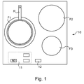
- the cooking apparatus is typically a hob 10 comprising a plurality of induction cooking heaters F1, F2, F3.
- the hob 10 comprises three induction hobs F1, F2, F3 distributed in the hob.
- induction hobs may be different.
- Each cooking hearth F1, F2, F3 is for example made from one or more inductive coils arranged under the hob.
- the cooking apparatus comprises all the means necessary for the control in operation of the cooking hobs F1, F2, F3.
- a control panel 11 for example tactile, allows the user to adjust the target power, and for example the operating time, of each cooking chamber F1, F2, F3 independently.
- each induction cooking hearth is associated with means for detecting a container disposed above each cooking chamber.
- These container detection means are generally implemented from the inductors constituting the cooking zone and also make it possible, in a conventional manner, to detect the presence or absence of a container R opposite the cooking zone considered. .
- each cooking hearth F1, F2, F3 can be spotted in the hob, for example using a silkscreen outline schematically the overall size of the cooking chamber F1, F2, F3.
- each firing chamber F1, F2, F3 consists of a spiral wound inductor
- the size of the firing chamber substantially corresponds to the diameter of the disk formed by the inductor.
- the size of the cooking hobs F1, F2, F3 can vary between 160 and 210 mm in diameter.
- each cooking chamber F1, F2, F3 varies for example between 2200 and 3100 W.
- the cooking appliance comprises several induction cooking stoves F1, F2, F3 which each deliver a different theoretical maximum power.
- a first cooking zone F1 has a theoretical maximum power P1Max greater than a theoretical maximum power P2Max associated with a second home.
- cooking F2 itself greater than a theoretical maximum power P3Max associated with a third cooking stove F3.
- the user poses for example a container R on a first cooking zone F1 as illustrated in the situation shown schematically in FIG. figure 1 .
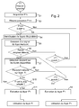
- the control method comprises, after switching on the first cooking zone F1, a first acquisition step S1 of a setpoint power P1c associated with the first cooking zone F1 covered with the receptacle R.
- this acquisition step S1 of a target power can be implemented by the user from the control panel 11 by conventional adjustment keys of the desired power.
- the user can optionally also enter a cooking time using the setting of a timer.
- the control method then continues with a measurement step S2 of a value representative of a power P1 m delivered to the container R placed on the first F1 cooking zone.
- This step consists in measuring the power that can be delivered to the container R by the first cooking zone F1 when it is put into operation according to the set power P1 c set by the user.
- the inductor or inductors constituting the cooking zone are operated in a conventional manner by a frequency-controlled inverter.
- control frequency of the inverter is high, for example of the order of 50 kHz.
- this value decreases so as to gradually increase the power delivered by the inductor (s) constituting the first cooking zone F1 until substantially reaching the value of the desired power P1 c.
- the power P1 m delivered to the receptacle R placed on the first cooking chamber F1 is then measured.
- This measured power P1 m depends in particular on the adaptation of the first cooking zone F1 to the container R.
- the relative size of the container R and the first cooking chamber F1 has an influence on the behavior of the inductor placed under the container R.
- the quality of the material used to make the container R vis-à-vis induction heating, the shape of the container, the structure of the bottom of the container, and possibly the presence of a coating can influence the adaptation of the container R for its induction heating by the first cooking chamber F1.
- the control method then comprises a comparison step S3 of the measured value P1 m with a value representative of the reference power P1 c.
- the values representative of the desired power P1c and of the measured power P1m are, for example, electrical values measurable by the control system, and for example a voltage or current value measured at the circuit formed by the inductor and the container placed on the first cooking chamber F1.
- the first cooking zone F1 is classified as being adapted to heat the container R when a ratio between the measured value P1 m and the value representative of the desired power P1 c is greater than one. predefined threshold.
- this ratio can correspond to 85%.
- the first cooking zone F1 is considered to be suitable for heating the container R and the control method of the cooking appliance is conventionally continued by using operation of the first cooking zone F1 to heat the container R.
- control method continues with an identification step S4, among the other cooking hobs. induction of at least one available cooking zone adapted to heat the container R.
- This identification step S4 is illustrated, without limitation, according to a more detailed embodiment of the invention. figure 3 .
- this identification step S4 consists in comparing the measured value P1 m and a value representative of the theoretical maximum power P2Max, P3Max delivered by the other cooking hobs F2, F3 of the hob, different from the first focus. F1 cooking.
- the identification step S4 firstly comprises a step comparing S41 adapted to verify if the ratio between the measured value P1 m and the representative value of the desired power P1 c is less than another preset threshold, and here set at 70%.
- This verification step S41 thus makes it possible to check whether the measured power P1 m is far away from the user-requested reference power P1 c. If not, then we will test the adaptation the second firing chamber F2, the closest in terms of design and theoretical maximum power of the first firing chamber F1. Conversely, if the difference between the measured power P1m and the desired power P1c is very large, it will be directly tested the possibility of using the third firing furnace F3 theoretical maximum power P3Max the weakest.
- comparison steps S42, S43 are implemented respectively for comparing the measured value P1 m and a value representative of a theoretical maximum power. P2Max, P3Max delivered by each cooking zone F2, F3.
- the cooking hobs F2, F3 are classified as a suitable cooking zone when the ratio between the measured value P1m and the value representative of the theoretical maximum power P2Max, P3Max is less than a second predefined threshold, here fixed as non-limiting example to 95%.
- a container detection step S44, S45 is carried out on these cooking burners F2, F3 to determine whether the second and third cooking burners F2, F3 are available cooking hobs.
- a classification step S46, S47 makes it possible to classify the second cooking zone F2 or the third cooking zone F3, when it is available, as a cooking zone suitable for heating the oven.
- container R since the ratio between the measured value P1 m and the representative value of the theoretical maximum power P2Max, P3Max associated with each cooking zone F2, F3 is less than the second predefined threshold.
- an emission step S5 of a focus warning signal unsuitable cooking is carried out.
- the wrong cooking stove warning signal is issued in association with the first cooking zone F1.
- the user can be informed of the maladaptation of the first cooking zone F1 to the heating of the container R, and this only if there is in the cooktop 10 another induction cooking hearth, likely to heat the container. R under higher adaptation conditions.
- the transmission step S5 of the warning signal can be implemented visually for the attention of the user.
- the incorrect cooking stove warning signal is information displayed on the control panel 11 of the hob 10, in association with the unsuitable cooking zone.
- a signal "no" is displayed in a display area dedicated to the display of the desired power associated with each cooking zone F1, F2, F3.
- a signal "no" is displayed in the set power display area dedicated to the first cooking zone F1.
- control method continues, following the issuance of such an unsuitable cooking stove warning signal, following the possible movement of the container R by the user on the hob 10.
- a detection step S6 of the withdrawal of the container R from the first cooking chamber F1 is carried out for a predetermined period of time ⁇ T1, equal for example to 10s.
- the control method repeats the identification steps S4 of an available cooking zone adapted to heat the container R and the emission step S5 of an incorrect cooking stove warning signal during the predetermined time period ⁇ T1.
- the control method continues with the use of the first firing chamber F1 for heating the container R in a conventional manner, to the desired power P1c requested by the user.
- the activation step S7 of the container detection is implemented in a conventional manner in a hob, by testing the behavior of each inductor constituting each cooking zone F1, F2, F3 of the hob 10 to verify whether or not covered by a receptacle R.
- a detection step S8 is implemented to detect the presence of the container R on another induction cooking furnace Fi, different from the first cooking zone F1.
- the detection step S8 is also implemented iteratively for a predetermined period of time ⁇ T2, equal for example to 10s.
- a test step S10 makes it possible to check whether this cooking hearth Fi corresponds to a focus available classified as a cooking stove adapted to the heating of the container R during the identification step S4 of an available cooking stove adapted to heat the container R.
- the S5 emission step of an unsuitable cooking stove warning signal is carried out in association with this other cooking stove Fi to indicate to the user that this other cooking zone is not identified as an available fireplace suitable for heating container R.
- the cooking chamber Fi covered by the container R corresponds to an available fireplace adapted to heat the container during the identification step S4
- the cooking chamber Fi is put in operating at the desired power P1 c associated with the first cooking zone F1 and an extinction step S11 of the first cooking zone F1 is implemented.
- the set of cooking parameters set by the user including the set power P1c and possibly the cooking time are transmitted to this new cooking chamber Fi to then allow the conventional use of this cooking hearth Fi to heat the R. container
- the measurement step S2 of a value representative of a power delivered to the container R placed on the first firing chamber F1 is implemented automatically after the acquisition step S1 of the desired power P1 c associated with the first F1 cooking stove.
- the measurement step S2 and all of the following steps of the control method could be implemented after actuation of a dedicated key 12 of the cooking apparatus 10.
- the control method then comprises a preliminary step for detecting the actuation of this dedicated key 12 of the cooking apparatus 10.
- the control and heating method of the container R continues in a conventional manner on the first focus of F1 cooking whatever the quality of the adaptation.
- the user can at any time actuate the dedicated key 12 to check the adaptation of the first cooking zone F1 to the heating of the container R according to the requested nominal power.
- the control method makes it possible to determine whether a first cooking zone F1 is well adapted to heating a container R and if it does not, to emit an incorrect cooking zone warning signal to the attention of the customer. the user so that he can choose a cooking stove better adapted.
- the values chosen to illustrate the ratios for determining whether a cooking stove is suitable or not are indicative and can vary, depending on the size and power of each cooking stove.
- the method described above with reference to the figure 2 can also be changed after the S4 identification and S5 emission steps of an unsuitable cooking stove warning signal in association with the first cooking zone F1.
- the control method may further comprise a step of issuing a cookstove warning signal adapted in combination with one of the cooking furnaces F2, F3 available and identified as suitable for heating the container R after the step identification S4 as implemented for example according to the embodiment of the figure 3 .
- the adapted cooking hearth warning signal may be information displayed on the control panel 11 of the cooking appliance 10, in association with the adapted cooking stove.
- a different signal such as "ok" can be displayed on another display zone associated with one of the other two cooking hobs F2, F3.
Landscapes
- Physics & Mathematics (AREA)
- Electromagnetism (AREA)
- Induction Heating Cooking Devices (AREA)
- Electric Stoves And Ranges (AREA)
- Cookers (AREA)
Applications Claiming Priority (1)
| Application Number | Priority Date | Filing Date | Title |
|---|---|---|---|
| FR1551751A FR3033471B1 (fr) | 2015-03-02 | 2015-03-02 | Procede de commande d'un appareil de cuisson et appareil de cuisson associe |
Publications (2)
| Publication Number | Publication Date |
|---|---|
| EP3065505A1 true EP3065505A1 (de) | 2016-09-07 |
| EP3065505B1 EP3065505B1 (de) | 2022-04-06 |
Family
ID=53008735
Family Applications (1)
| Application Number | Title | Priority Date | Filing Date |
|---|---|---|---|
| EP16157136.9A Active EP3065505B1 (de) | 2015-03-02 | 2016-02-24 | Verfahren zur steuerung eines kochgeräts und entsprechendes kochgerät |
Country Status (4)
| Country | Link |
|---|---|
| EP (1) | EP3065505B1 (de) |
| ES (1) | ES2920808T3 (de) |
| FR (1) | FR3033471B1 (de) |
| MA (1) | MA40356A (de) |
Citations (4)
| Publication number | Priority date | Publication date | Assignee | Title |
|---|---|---|---|---|
| US4686340A (en) * | 1985-04-17 | 1987-08-11 | Sanyo Electric Co., Ltd. | Induction heating apparatus with unsuitable load detecting circuit |
| EP2389045A1 (de) * | 2010-05-21 | 2011-11-23 | FagorBrandt SAS | Steuerungsverfahren für den Betrieb einer Gruppe von Induktoren einer Induktionskochplatte |
| EP2453715A2 (de) * | 2010-11-11 | 2012-05-16 | BSH Bosch und Siemens Hausgeräte GmbH | Haushalts-Betriebsgerät und Verfahren zum Zentrieren eines Aufsatzgeräts auf einem Haushalts-Betriebsgerät |
| EP2706816A1 (de) | 2012-09-05 | 2014-03-12 | E.G.O. ELEKTRO-GERÄTEBAU GmbH | Bedienverfahren für ein Kochfeld und Kochfeld |
-
2015
- 2015-03-02 FR FR1551751A patent/FR3033471B1/fr active Active
-
2016
- 2016-02-24 EP EP16157136.9A patent/EP3065505B1/de active Active
- 2016-02-24 MA MA040356A patent/MA40356A/fr unknown
- 2016-02-24 ES ES16157136T patent/ES2920808T3/es active Active
Patent Citations (4)
| Publication number | Priority date | Publication date | Assignee | Title |
|---|---|---|---|---|
| US4686340A (en) * | 1985-04-17 | 1987-08-11 | Sanyo Electric Co., Ltd. | Induction heating apparatus with unsuitable load detecting circuit |
| EP2389045A1 (de) * | 2010-05-21 | 2011-11-23 | FagorBrandt SAS | Steuerungsverfahren für den Betrieb einer Gruppe von Induktoren einer Induktionskochplatte |
| EP2453715A2 (de) * | 2010-11-11 | 2012-05-16 | BSH Bosch und Siemens Hausgeräte GmbH | Haushalts-Betriebsgerät und Verfahren zum Zentrieren eines Aufsatzgeräts auf einem Haushalts-Betriebsgerät |
| EP2706816A1 (de) | 2012-09-05 | 2014-03-12 | E.G.O. ELEKTRO-GERÄTEBAU GmbH | Bedienverfahren für ein Kochfeld und Kochfeld |
Also Published As
| Publication number | Publication date |
|---|---|
| MA40356A (fr) | 2016-09-07 |
| FR3033471A1 (fr) | 2016-09-09 |
| ES2920808T3 (es) | 2022-08-09 |
| FR3033471B1 (fr) | 2017-03-17 |
| EP3065505B1 (de) | 2022-04-06 |
Similar Documents
| Publication | Publication Date | Title |
|---|---|---|
| EP2265087B1 (de) | Kochherd mit mehreren unabhängigen Kochplatten | |
| US9675199B2 (en) | Boil and boil-dry detection systems for cooking appliances using vibration sensors | |
| EP2551600B1 (de) | Kochfeld und Verfahren zur Steuerung, wenn das Kochfeld in Betrieb ist | |
| EP2166290B1 (de) | Method for controlling a hob | |
| EP0491820B1 (de) | Regelvorrichtung und -verfahren für kochgerät | |
| EP0412875B1 (de) | Temperaturmessvorrichtung für Induktionskochgerät und Gerät mit einer solchen Vorrichtung | |
| US10788220B2 (en) | Determining cookware location on a cooktop appliance based on temperature response | |
| US20160022086A1 (en) | Cooktop appliances with intelligent response to cooktop audio | |
| CN105532073A (zh) | 用于确定炊具对于感应烹饪灶具的相应感应线圈的适用性的方法和装置 | |
| CN110848745A (zh) | 燃气灶控制方法及装置、燃气灶、计算机设备、存储介质 | |
| EP2440007B1 (de) | Steuerverfahren bei Betrieb einer Reihe von Induktoren eines Induktionskochfeldes, und zugehöriges Induktionskochfeld | |
| EP2440011A2 (de) | Steuerverfahren bei Betrieb einer Reihe von Induktoren eines Induktionskochfeldes, und zugehöriges Induktionskochfeld | |
| EP1473554B1 (de) | Kochgeschirr und Verfahren und Vorrichtung zur Regelung der Heizmitteln einer Kochapparat | |
| EP3065505A1 (de) | Verfahren zur steuerung eines kochgeräts, und entsprechendes kochgerät | |
| CN109237527B (zh) | 防干烧的控制方法和防干烧系统 | |
| EP2341757A1 (de) | Verfahren und Vorrichtung zur Bestimmung der minimalen induzierten Dauerleistung, insbesondere eines Induktionskochgeräts | |
| EP2747514A1 (de) | Verfahren und Vorrichtung zur Leistungszuführung von Induktionsmitteln | |
| CN116614910B (zh) | 一种电磁炉控制方法、系统、终端设备及存储介质 | |
| EP2144480B1 (de) | Verfahren zur Ansteuerung von zumindest einem Heizelement eines Gargeräts | |
| EP3291641B1 (de) | Steuerungsvorrichtung, steuerungsverfahren und induktionskocher | |
| EP2440008B1 (de) | Steuerverfahren bei Betrieb einer Reihe von Induktoren eines Induktionskochfeldes, und zugehöriges Induktionskochfeld | |
| EP2200399B1 (de) | Verfahren zur Stromversorgung mit der Leistung von mindestens einem Induktor und Kochgerät, bei dem dieses Verfahren umgesetzt ist | |
| CN115405959A (zh) | 一种防干烧方法、系统、灶具及存储介质 | |
| CN105805791B (zh) | 高周波加热装置 | |
| EP3846588A1 (de) | Verfahren zur steuerung der leistung und kochfeld, das dieses verfahren umsetzt |
Legal Events
| Date | Code | Title | Description |
|---|---|---|---|
| PUAI | Public reference made under article 153(3) epc to a published international application that has entered the european phase |
Free format text: ORIGINAL CODE: 0009012 |
|
| AK | Designated contracting states |
Kind code of ref document: A1 Designated state(s): AL AT BE BG CH CY CZ DE DK EE ES FI FR GB GR HR HU IE IS IT LI LT LU LV MC MK MT NL NO PL PT RO RS SE SI SK SM TR |
|
| AX | Request for extension of the european patent |
Extension state: BA ME |
|
| STAA | Information on the status of an ep patent application or granted ep patent |
Free format text: STATUS: REQUEST FOR EXAMINATION WAS MADE |
|
| 17P | Request for examination filed |
Effective date: 20170220 |
|
| RAV | Requested validation state of the european patent: fee paid |
Extension state: MA Effective date: 20170220 |
|
| RBV | Designated contracting states (corrected) |
Designated state(s): AL AT BE BG CH CY CZ DE DK EE ES FI FR GB GR HR HU IE IS IT LI LT LU LV MC MK MT NL NO PL PT RO RS SE SI SK SM TR |
|
| STAA | Information on the status of an ep patent application or granted ep patent |
Free format text: STATUS: EXAMINATION IS IN PROGRESS |
|
| 17Q | First examination report despatched |
Effective date: 20180122 |
|
| GRAP | Despatch of communication of intention to grant a patent |
Free format text: ORIGINAL CODE: EPIDOSNIGR1 |
|
| STAA | Information on the status of an ep patent application or granted ep patent |
Free format text: STATUS: GRANT OF PATENT IS INTENDED |
|
| INTG | Intention to grant announced |
Effective date: 20211018 |
|
| GRAS | Grant fee paid |
Free format text: ORIGINAL CODE: EPIDOSNIGR3 |
|
| GRAA | (expected) grant |
Free format text: ORIGINAL CODE: 0009210 |
|
| STAA | Information on the status of an ep patent application or granted ep patent |
Free format text: STATUS: THE PATENT HAS BEEN GRANTED |
|
| RIN1 | Information on inventor provided before grant (corrected) |
Inventor name: BARBEROUSSE, AURELIEN Inventor name: ANDRE, XAVIER Inventor name: BUGEIA, JEAN-MARC Inventor name: GOUARDO, DIDIER |
|
| AK | Designated contracting states |
Kind code of ref document: B1 Designated state(s): AL AT BE BG CH CY CZ DE DK EE ES FI FR GB GR HR HU IE IS IT LI LT LU LV MC MK MT NL NO PL PT RO RS SE SI SK SM TR |
|
| REG | Reference to a national code |
Ref country code: GB Ref legal event code: FG4D Free format text: NOT ENGLISH |
|
| REG | Reference to a national code |
Ref country code: CH Ref legal event code: EP |
|
| REG | Reference to a national code |
Ref country code: AT Ref legal event code: REF Ref document number: 1482633 Country of ref document: AT Kind code of ref document: T Effective date: 20220415 |
|
| REG | Reference to a national code |
Ref country code: IE Ref legal event code: FG4D Free format text: LANGUAGE OF EP DOCUMENT: FRENCH |
|
| REG | Reference to a national code |
Ref country code: DE Ref legal event code: R096 Ref document number: 602016070690 Country of ref document: DE |
|
| REG | Reference to a national code |
Ref country code: LT Ref legal event code: MG9D |
|
| REG | Reference to a national code |
Ref country code: ES Ref legal event code: FG2A Ref document number: 2920808 Country of ref document: ES Kind code of ref document: T3 Effective date: 20220809 |
|
| REG | Reference to a national code |
Ref country code: NL Ref legal event code: MP Effective date: 20220406 |
|
| REG | Reference to a national code |
Ref country code: AT Ref legal event code: MK05 Ref document number: 1482633 Country of ref document: AT Kind code of ref document: T Effective date: 20220406 |
|
| PG25 | Lapsed in a contracting state [announced via postgrant information from national office to epo] |
Ref country code: NL Free format text: LAPSE BECAUSE OF FAILURE TO SUBMIT A TRANSLATION OF THE DESCRIPTION OR TO PAY THE FEE WITHIN THE PRESCRIBED TIME-LIMIT Effective date: 20220406 |
|
| PG25 | Lapsed in a contracting state [announced via postgrant information from national office to epo] |
Ref country code: SE Free format text: LAPSE BECAUSE OF FAILURE TO SUBMIT A TRANSLATION OF THE DESCRIPTION OR TO PAY THE FEE WITHIN THE PRESCRIBED TIME-LIMIT Effective date: 20220406 Ref country code: PT Free format text: LAPSE BECAUSE OF FAILURE TO SUBMIT A TRANSLATION OF THE DESCRIPTION OR TO PAY THE FEE WITHIN THE PRESCRIBED TIME-LIMIT Effective date: 20220808 Ref country code: NO Free format text: LAPSE BECAUSE OF FAILURE TO SUBMIT A TRANSLATION OF THE DESCRIPTION OR TO PAY THE FEE WITHIN THE PRESCRIBED TIME-LIMIT Effective date: 20220706 Ref country code: LT Free format text: LAPSE BECAUSE OF FAILURE TO SUBMIT A TRANSLATION OF THE DESCRIPTION OR TO PAY THE FEE WITHIN THE PRESCRIBED TIME-LIMIT Effective date: 20220406 Ref country code: HR Free format text: LAPSE BECAUSE OF FAILURE TO SUBMIT A TRANSLATION OF THE DESCRIPTION OR TO PAY THE FEE WITHIN THE PRESCRIBED TIME-LIMIT Effective date: 20220406 Ref country code: GR Free format text: LAPSE BECAUSE OF FAILURE TO SUBMIT A TRANSLATION OF THE DESCRIPTION OR TO PAY THE FEE WITHIN THE PRESCRIBED TIME-LIMIT Effective date: 20220707 Ref country code: FI Free format text: LAPSE BECAUSE OF FAILURE TO SUBMIT A TRANSLATION OF THE DESCRIPTION OR TO PAY THE FEE WITHIN THE PRESCRIBED TIME-LIMIT Effective date: 20220406 Ref country code: BG Free format text: LAPSE BECAUSE OF FAILURE TO SUBMIT A TRANSLATION OF THE DESCRIPTION OR TO PAY THE FEE WITHIN THE PRESCRIBED TIME-LIMIT Effective date: 20220706 Ref country code: AT Free format text: LAPSE BECAUSE OF FAILURE TO SUBMIT A TRANSLATION OF THE DESCRIPTION OR TO PAY THE FEE WITHIN THE PRESCRIBED TIME-LIMIT Effective date: 20220406 |
|
| PG25 | Lapsed in a contracting state [announced via postgrant information from national office to epo] |
Ref country code: RS Free format text: LAPSE BECAUSE OF FAILURE TO SUBMIT A TRANSLATION OF THE DESCRIPTION OR TO PAY THE FEE WITHIN THE PRESCRIBED TIME-LIMIT Effective date: 20220406 Ref country code: PL Free format text: LAPSE BECAUSE OF FAILURE TO SUBMIT A TRANSLATION OF THE DESCRIPTION OR TO PAY THE FEE WITHIN THE PRESCRIBED TIME-LIMIT Effective date: 20220406 Ref country code: LV Free format text: LAPSE BECAUSE OF FAILURE TO SUBMIT A TRANSLATION OF THE DESCRIPTION OR TO PAY THE FEE WITHIN THE PRESCRIBED TIME-LIMIT Effective date: 20220406 Ref country code: IS Free format text: LAPSE BECAUSE OF FAILURE TO SUBMIT A TRANSLATION OF THE DESCRIPTION OR TO PAY THE FEE WITHIN THE PRESCRIBED TIME-LIMIT Effective date: 20220806 |
|
| REG | Reference to a national code |
Ref country code: DE Ref legal event code: R097 Ref document number: 602016070690 Country of ref document: DE |
|
| PG25 | Lapsed in a contracting state [announced via postgrant information from national office to epo] |
Ref country code: SM Free format text: LAPSE BECAUSE OF FAILURE TO SUBMIT A TRANSLATION OF THE DESCRIPTION OR TO PAY THE FEE WITHIN THE PRESCRIBED TIME-LIMIT Effective date: 20220406 Ref country code: SK Free format text: LAPSE BECAUSE OF FAILURE TO SUBMIT A TRANSLATION OF THE DESCRIPTION OR TO PAY THE FEE WITHIN THE PRESCRIBED TIME-LIMIT Effective date: 20220406 Ref country code: RO Free format text: LAPSE BECAUSE OF FAILURE TO SUBMIT A TRANSLATION OF THE DESCRIPTION OR TO PAY THE FEE WITHIN THE PRESCRIBED TIME-LIMIT Effective date: 20220406 Ref country code: EE Free format text: LAPSE BECAUSE OF FAILURE TO SUBMIT A TRANSLATION OF THE DESCRIPTION OR TO PAY THE FEE WITHIN THE PRESCRIBED TIME-LIMIT Effective date: 20220406 Ref country code: DK Free format text: LAPSE BECAUSE OF FAILURE TO SUBMIT A TRANSLATION OF THE DESCRIPTION OR TO PAY THE FEE WITHIN THE PRESCRIBED TIME-LIMIT Effective date: 20220406 Ref country code: CZ Free format text: LAPSE BECAUSE OF FAILURE TO SUBMIT A TRANSLATION OF THE DESCRIPTION OR TO PAY THE FEE WITHIN THE PRESCRIBED TIME-LIMIT Effective date: 20220406 |
|
| PLBE | No opposition filed within time limit |
Free format text: ORIGINAL CODE: 0009261 |
|
| STAA | Information on the status of an ep patent application or granted ep patent |
Free format text: STATUS: NO OPPOSITION FILED WITHIN TIME LIMIT |
|
| 26N | No opposition filed |
Effective date: 20230110 |
|
| PG25 | Lapsed in a contracting state [announced via postgrant information from national office to epo] |
Ref country code: AL Free format text: LAPSE BECAUSE OF FAILURE TO SUBMIT A TRANSLATION OF THE DESCRIPTION OR TO PAY THE FEE WITHIN THE PRESCRIBED TIME-LIMIT Effective date: 20220406 |
|
| PG25 | Lapsed in a contracting state [announced via postgrant information from national office to epo] |
Ref country code: SI Free format text: LAPSE BECAUSE OF FAILURE TO SUBMIT A TRANSLATION OF THE DESCRIPTION OR TO PAY THE FEE WITHIN THE PRESCRIBED TIME-LIMIT Effective date: 20220406 |
|
| P01 | Opt-out of the competence of the unified patent court (upc) registered |
Effective date: 20230524 |
|
| PG25 | Lapsed in a contracting state [announced via postgrant information from national office to epo] |
Ref country code: MC Free format text: LAPSE BECAUSE OF FAILURE TO SUBMIT A TRANSLATION OF THE DESCRIPTION OR TO PAY THE FEE WITHIN THE PRESCRIBED TIME-LIMIT Effective date: 20220406 |
|
| REG | Reference to a national code |
Ref country code: CH Ref legal event code: PL |
|
| REG | Reference to a national code |
Ref country code: BE Ref legal event code: MM Effective date: 20230228 |
|
| GBPC | Gb: european patent ceased through non-payment of renewal fee |
Effective date: 20230224 |
|
| PG25 | Lapsed in a contracting state [announced via postgrant information from national office to epo] |
Ref country code: LU Free format text: LAPSE BECAUSE OF NON-PAYMENT OF DUE FEES Effective date: 20230224 Ref country code: LI Free format text: LAPSE BECAUSE OF NON-PAYMENT OF DUE FEES Effective date: 20230228 Ref country code: CH Free format text: LAPSE BECAUSE OF NON-PAYMENT OF DUE FEES Effective date: 20230228 |
|
| REG | Reference to a national code |
Ref country code: IE Ref legal event code: MM4A |
|
| PG25 | Lapsed in a contracting state [announced via postgrant information from national office to epo] |
Ref country code: GB Free format text: LAPSE BECAUSE OF NON-PAYMENT OF DUE FEES Effective date: 20230224 |
|
| PG25 | Lapsed in a contracting state [announced via postgrant information from national office to epo] |
Ref country code: IE Free format text: LAPSE BECAUSE OF NON-PAYMENT OF DUE FEES Effective date: 20230224 Ref country code: GB Free format text: LAPSE BECAUSE OF NON-PAYMENT OF DUE FEES Effective date: 20230224 |
|
| PG25 | Lapsed in a contracting state [announced via postgrant information from national office to epo] |
Ref country code: BE Free format text: LAPSE BECAUSE OF NON-PAYMENT OF DUE FEES Effective date: 20230228 |
|
| PG25 | Lapsed in a contracting state [announced via postgrant information from national office to epo] |
Ref country code: BG Free format text: LAPSE BECAUSE OF FAILURE TO SUBMIT A TRANSLATION OF THE DESCRIPTION OR TO PAY THE FEE WITHIN THE PRESCRIBED TIME-LIMIT Effective date: 20220406 |
|
| PG25 | Lapsed in a contracting state [announced via postgrant information from national office to epo] |
Ref country code: BG Free format text: LAPSE BECAUSE OF FAILURE TO SUBMIT A TRANSLATION OF THE DESCRIPTION OR TO PAY THE FEE WITHIN THE PRESCRIBED TIME-LIMIT Effective date: 20220406 |
|
| PGFP | Annual fee paid to national office [announced via postgrant information from national office to epo] |
Ref country code: DE Payment date: 20250212 Year of fee payment: 10 |
|
| PGFP | Annual fee paid to national office [announced via postgrant information from national office to epo] |
Ref country code: ES Payment date: 20250317 Year of fee payment: 10 |
|
| PGFP | Annual fee paid to national office [announced via postgrant information from national office to epo] |
Ref country code: FR Payment date: 20250225 Year of fee payment: 10 |
|
| PGFP | Annual fee paid to national office [announced via postgrant information from national office to epo] |
Ref country code: IT Payment date: 20250207 Year of fee payment: 10 |
|
| PG25 | Lapsed in a contracting state [announced via postgrant information from national office to epo] |
Ref country code: CY Free format text: LAPSE BECAUSE OF FAILURE TO SUBMIT A TRANSLATION OF THE DESCRIPTION OR TO PAY THE FEE WITHIN THE PRESCRIBED TIME-LIMIT; INVALID AB INITIO Effective date: 20160224 |
|
| PG25 | Lapsed in a contracting state [announced via postgrant information from national office to epo] |
Ref country code: HU Free format text: LAPSE BECAUSE OF FAILURE TO SUBMIT A TRANSLATION OF THE DESCRIPTION OR TO PAY THE FEE WITHIN THE PRESCRIBED TIME-LIMIT; INVALID AB INITIO Effective date: 20160224 |
|
| VS25 | Lapsed in a validation state [announced via postgrant information from nat. office to epo] |
Ref country code: MA Free format text: FAILURE TO ELECT DOMICILE IN THE NATIONAL COUNTRY Effective date: 20220707 |
|
| PG25 | Lapsed in a contracting state [announced via postgrant information from national office to epo] |
Ref country code: TR Free format text: LAPSE BECAUSE OF FAILURE TO SUBMIT A TRANSLATION OF THE DESCRIPTION OR TO PAY THE FEE WITHIN THE PRESCRIBED TIME-LIMIT Effective date: 20220406 |