EP3065914B1 - Machine-outil manuelle - Google Patents
Machine-outil manuelle Download PDFInfo
- Publication number
- EP3065914B1 EP3065914B1 EP14790626.7A EP14790626A EP3065914B1 EP 3065914 B1 EP3065914 B1 EP 3065914B1 EP 14790626 A EP14790626 A EP 14790626A EP 3065914 B1 EP3065914 B1 EP 3065914B1
- Authority
- EP
- European Patent Office
- Prior art keywords
- catcher
- working axis
- hand
- machine tool
- striker
- Prior art date
- Legal status (The legal status is an assumption and is not a legal conclusion. Google has not performed a legal analysis and makes no representation as to the accuracy of the status listed.)
- Active
Links
Images

Classifications
-
- B—PERFORMING OPERATIONS; TRANSPORTING
- B25—HAND TOOLS; PORTABLE POWER-DRIVEN TOOLS; MANIPULATORS
- B25D—PERCUSSIVE TOOLS
- B25D17/00—Details of, or accessories for, portable power-driven percussive tools
- B25D17/11—Arrangements of noise-damping means
-
- B—PERFORMING OPERATIONS; TRANSPORTING
- B25—HAND TOOLS; PORTABLE POWER-DRIVEN TOOLS; MANIPULATORS
- B25D—PERCUSSIVE TOOLS
- B25D17/00—Details of, or accessories for, portable power-driven percussive tools
- B25D17/06—Hammer pistons; Anvils ; Guide-sleeves for pistons
-
- B—PERFORMING OPERATIONS; TRANSPORTING
- B25—HAND TOOLS; PORTABLE POWER-DRIVEN TOOLS; MANIPULATORS
- B25D—PERCUSSIVE TOOLS
- B25D2250/00—General details of portable percussive tools; Components used in portable percussive tools
- B25D2250/191—Ram catchers for stopping the ram when entering idling mode
-
- B—PERFORMING OPERATIONS; TRANSPORTING
- B25—HAND TOOLS; PORTABLE POWER-DRIVEN TOOLS; MANIPULATORS
- B25D—PERCUSSIVE TOOLS
- B25D2250/00—General details of portable percussive tools; Components used in portable percussive tools
- B25D2250/245—Spatial arrangement of components of the tool relative to each other
-
- B—PERFORMING OPERATIONS; TRANSPORTING
- B25—HAND TOOLS; PORTABLE POWER-DRIVEN TOOLS; MANIPULATORS
- B25D—PERCUSSIVE TOOLS
- B25D2250/00—General details of portable percussive tools; Components used in portable percussive tools
- B25D2250/371—Use of springs
-
- B—PERFORMING OPERATIONS; TRANSPORTING
- B25—HAND TOOLS; PORTABLE POWER-DRIVEN TOOLS; MANIPULATORS
- B25D—PERCUSSIVE TOOLS
- B25D2250/00—General details of portable percussive tools; Components used in portable percussive tools
- B25D2250/391—Use of weights; Weight properties of the tool
Definitions
- the present invention relates to a portable power tool with a striking mechanism, in particular for use with chiseling tools, according to the preamble of claim 1 and as from EP 1238759 A known.
- a striking mechanism has several moving components that repeatedly move along a working axis and hit each other. This leads to a considerable noise. Precise guidance of the striking components parallel to the working axis prevents skewing of the striking components and rattling due to partial radial movement.
- the hand tool according to the invention is defined by the features of claim 1 and has a tool holder in which a tool on a working axis in a direction of impact is movable.
- An impact mechanism has a beater coupled via a pneumatic chamber to a pathogen that is moved periodically along the working axis and an intermediate beater arranged in the direction of impact after the beater.
- the intermediate beater is guided in a sliding bearing, with a tolerance coaxial to the working axis
- the intermediate beater has an annular bead.
- a hollow cylindrical catcher is arranged in the direction of impact in front of the bead. The catcher is movably guided on a sliding surface with a radial clearance along the working axis.
- the radial clearance is at least three times as large as a tolerance of the leadership of the intermediate beater in the sliding bearing.
- the beating components are strictly managed as usual. In contrast, it may prove advantageous not to stringently guide a catcher for the intermediate bat. Although this can now move radially and thereby rattle, the overall noise is lower.
- the impact of the intermediate impactor stimulates a radial vibration in the catcher, which also depends on the guidance.
- the strict leadership proves to be unfavorable, since the resulting higher frequencies resonantly excite the housing.
- the mass of the catcher is between 20% and 40% of the mass of the intermediate beater.
- the catcher may be supported against the impact direction on a damping element.
- the catcher can be inserted under prestress between the damping element and a further damping element arranged in the direction of impact.
- An embodiment provides that a spring element spans a radial outer surface of the catcher.
- the spring element centered the catcher to the working axis after an impact of the intermediate beater has occurred.
- Fig. 1 schematically shows a hammer drill 1 as an example of a chiseling hand tool .
- the hammer drill 1 has a tool holder 2, in which a shank end 3 of a tool, such as a chisel 4, can be used.
- a primary drive of the hammer drill 1 is a motor 5, which drives a striking mechanism 6 and an output shaft 7 .
- a battery pack 8 or a power line supplies the motor 5 with power.
- a user can guide the hammer drill 1 by means of a handle 9 and take the hammer drill 1 is operated by means of a switch system 10th
- the hammer drill 1 rotates the drill 4 continuously about a working axis 11 and can beat the drill 4 in the direction of impact 12 along the working axis 11 in a substrate.
- the percussion 6 is a pneumatic percussion 6.
- An exciter piston 13 and a racket 14 are movably guided in a guide tube 15 in the striking mechanism 6 along the working axis 11 .
- the exciter piston 13 is connected to the motor 5 via an eccentric 16 coupled and forced to a periodic, linear motion.
- a connecting rod connects the eccentric 16 with the excitation piston 13.
- An air spring formed by a pneumatic chamber 17 between the excitation piston 13 and the racket 14 couples a movement of the racket 14 to the movement of the exciter piston 13 .
- the racket 14 indirectly transmits a portion of its momentum to the chisel 4 via a substantially stationary intermediate racket 18.
- the percussion unit 6, and preferably the further drive components, are disposed within a machine housing 19 .
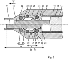
- the intermediate beater 18 has a substantially cylindrical base body 20.
- the intermediate beater 18 is guided in a sliding bearing 21, 22 coaxial with the working axis 11 .
- the exemplary two-part sliding bearing 21, 22 encloses with a front sleeve 21, a machine-side end of the base body 20 and a rear sleeve 22, the tool-side end of the base body 20.
- the diameter of the base body 20 deviates by a distance 23 of less than 50 microns from the inner diameter the sleeves 21, 22 from. This corresponds to the typical for plain bearings 21, 22 tolerance H7 for the sleeves 21, 22 and g7 for the intermediate beater 18, each according to the ISO standard.
- the tight tolerance ensures coaxial guidance, even with forces occurring in the range of 10 kN during impact.
- the intermediate beater 18 is between a working position (upper half of the picture Fig. 2 ) and an advanced in the direction of impact 12 position (lower half Fig. 2 ) movable.
- the intermediate beater 18 has a relative to the base 20 radially projecting bead 24, which is preferably provided in a central portion of the intermediate beater 18 .
- the bead 24 bears against the impact direction 12 on a catcher 25 when the intermediate beater 18 is in the working position.
- the catcher 25 has a hollow cylindrical shape with a radial outer surface 26.
- the exemplary catcher 25 has a radially inwardly projecting collar 27, against which the bead 24 bears against the impact direction 12 .
- a length 28 of the catcher 25, in particular the radial outer surface 26 is in the range of 10% and 25% of the length 29 of the intermediate beater 18.
- the movement of the intermediate beater 18 in the direction of impact 12 is stopped by a damped stop 30 , if at this the bead 24th comes in the direction of impact 12 to concern.
- the free path of the intermediate beater 18 from the working position to the stop 30 is small hammer drills in the range of 1 cm and 3 cm and large chisel in the range of 3 cm to 5 cm.
- the catcher 25 is supported against the direction of impact 12 by a damping element 31 on the machine housing 19 .
- the catcher 25 shifts slightly over the Housing, when the intermediate beater 18 bounces against the catcher 25 .
- the catcher 25 also has a relative to the intermediate beater 18 is not negligible mass to reduce the bounce.
- the mass of the catcher 25 is in the range of 20% to 40% of the mass of the intermediate beater 18.
- the large mass of the catcher 25 results from its axial dimension 28.
- the catcher 25 is preferably arranged between the damping element 31 and another in the direction of impact 12 Clamped damping element 32 .
- the two damping elements 31, 32 are biased along the working axis 11 .
- the catcher 25 is held along the working axis 11 by the two damping or spring elements 31, 32 in a rest position.
- the catcher 25 is coaxial with the working axis 11, that is, coaxial with the intermediate beater 18, out.
- the axial guidance of the catcher 25 is effected by its cylindrical outer surface 26.
- the axial dimension of the outer surface 26 is approximately equal to the length of the catcher 25.
- the counterpart of the guide can be done for example by a cylindrical radial inner surface 33 of the machine housing 19 .
- the guide is provided with a clear radial play 34 .
- the clearance 34 should be at least 0.15 mm, ie more than three times the guide tolerance 23 of the slide bearing 21, 22 for the intermediate beater 18.
- the play 34 is in the radial direction between the metallic outer surface 26 of the catcher 25 and the leading metallic inner surface 33rd , here the machine housing 19 to determine.
- the high tolerance proves to be favorable in order to reduce the noise of the collision of the impact pad 18 on the catcher 25 .
- the catcher 25 may be provided with radial spring elements 35 made of an elastomer, which surround the outer surface 26 and bear against the inner surface 33 of the guide 36 .
- the front sliding bearing 21 may have an inserted sealing ring 37 , which the tolerance 23 is arranged balancing on the inside of the sleeve 21 .
- the sealing ring 37 strips off fine dust from the intermediate beater 18 , and prevents penetration of the dust in the impact mechanism. 6
- the guide tube 15 bz is a separate component to the machine housing 19 bz , which is arranged completely within the machine housing 19 .
- the guide tube 15 may also be partially exposed, ergo form part of the outer machine housing 19 .
Landscapes
- Engineering & Computer Science (AREA)
- Mechanical Engineering (AREA)
- Percussive Tools And Related Accessories (AREA)
Claims (5)
- Machine-outil manuelle comportant :un porte-outil (2) dans lequel un outil (4) peut être inséré de manière à pouvoir se déplacer sur un axe de travail (11) dans une direction de percussion (12),un mécanisme de percussion (6) comportant un percuteur (14) couplé, par l'intermédiaire d'une chambre pneumatique (17), à un piston d'excitation (13) se déplaçant périodiquement le long de l'axe de travail (11), et un percuteur intermédiaire (18) agencé après le percuteur (14) dans la direction de percussion (12),dans laquelle le percuteur intermédiaire (18) est guidé dans un palier lisse (21, 22) avec une tolérance (23) coaxialement à l'axe de travail (11), et dans laquelle le percuteur intermédiaire (18) comporte un bourrelet annulaire (24),un doigt cylindrique creux (25) agencé avant le bourrelet (24) dans la direction de percussion (12),une surface de glissement (33), le doigt (25) étant guidé de manière à pouvoir se déplacer avec un jeu radial (34) le long de l'axe de travail (11),caractérisée en ce que le jeu radial (34) est au moins égal au triple d'une tolérance de guidage du percuteur intermédiaire (18) dans le palier lisse (21, 22) etla masse du doigt (25) représente entre 20 % et 40 % de la masse du percuteur intermédiaire (18).
- Machine-outil manuelle selon la revendication 1, caractérisée en ce que le doigt (25) est supporté par un élément d'amortissement (31) dans une direction opposée à la direction de percussion (12).
- Machine-outil manuelle selon la revendication 2, caractérisée en ce que le doigt (25) est inséré sous précontrainte entre l'élément d'amortissement (31) et un élément d'amortissement supplémentaire (32) agencé dans la direction de percussion (12).
- Machine-outil manuelle selon l'une des revendications précédentes, caractérisée en ce qu'un élément à ressort (35) couvre le pourtour d'une surface extérieure radiale (26) du doigt (25).
- Machine-outil manuelle selon l'une des revendications précédentes, caractérisée en ce que le doigt (25) est en acier.
Priority Applications (1)
| Application Number | Priority Date | Filing Date | Title |
|---|---|---|---|
| EP14790626.7A EP3065914B1 (fr) | 2013-11-06 | 2014-10-30 | Machine-outil manuelle |
Applications Claiming Priority (3)
| Application Number | Priority Date | Filing Date | Title |
|---|---|---|---|
| EP20130191708 EP2871030A1 (fr) | 2013-11-06 | 2013-11-06 | Machine-outil manuelle |
| PCT/EP2014/073304 WO2015067517A1 (fr) | 2013-11-06 | 2014-10-30 | Machine-outil portative |
| EP14790626.7A EP3065914B1 (fr) | 2013-11-06 | 2014-10-30 | Machine-outil manuelle |
Publications (2)
| Publication Number | Publication Date |
|---|---|
| EP3065914A1 EP3065914A1 (fr) | 2016-09-14 |
| EP3065914B1 true EP3065914B1 (fr) | 2019-12-04 |
Family
ID=49518827
Family Applications (2)
| Application Number | Title | Priority Date | Filing Date |
|---|---|---|---|
| EP20130191708 Withdrawn EP2871030A1 (fr) | 2013-11-06 | 2013-11-06 | Machine-outil manuelle |
| EP14790626.7A Active EP3065914B1 (fr) | 2013-11-06 | 2014-10-30 | Machine-outil manuelle |
Family Applications Before (1)
| Application Number | Title | Priority Date | Filing Date |
|---|---|---|---|
| EP20130191708 Withdrawn EP2871030A1 (fr) | 2013-11-06 | 2013-11-06 | Machine-outil manuelle |
Country Status (4)
| Country | Link |
|---|---|
| US (1) | US10286537B2 (fr) |
| EP (2) | EP2871030A1 (fr) |
| CN (1) | CN105705300A (fr) |
| WO (1) | WO2015067517A1 (fr) |
Families Citing this family (4)
| Publication number | Priority date | Publication date | Assignee | Title |
|---|---|---|---|---|
| EP3000560A1 (fr) * | 2014-09-25 | 2016-03-30 | HILTI Aktiengesellschaft | Appareil d'enfoncement à ressort à gaz |
| EP3231560A1 (fr) * | 2016-04-13 | 2017-10-18 | HILTI Aktiengesellschaft | Machine-outil portative |
| EP3822036A1 (fr) * | 2019-11-12 | 2021-05-19 | Hilti Aktiengesellschaft | Agencement de mécanisme de frappe |
| EP3822037A1 (fr) * | 2019-11-15 | 2021-05-19 | Hilti Aktiengesellschaft | Agencement de mécanisme de percussion |
Family Cites Families (6)
| Publication number | Priority date | Publication date | Assignee | Title |
|---|---|---|---|---|
| DE2844109A1 (de) | 1978-10-10 | 1980-04-24 | Bosch Gmbh Robert | Handwerkzeugmaschine, insbesondere bohr- und/oder schlaghammer |
| ES2208623T3 (es) * | 2001-03-07 | 2004-06-16 | Black & Decker Inc. | Martillo. |
| DE102005000042A1 (de) | 2005-04-25 | 2006-10-26 | Hilti Ag | Bohr-oder Meisselhammer |
| DE102006000209A1 (de) | 2006-05-05 | 2007-11-15 | Hilti Ag | Handwerkzeugmaschine mit Schlagwerkzeugaufnahme |
| DE102006000533A1 (de) | 2006-12-18 | 2008-06-19 | Hilti Ag | Handwerkzeugmaschine mit pneumatischem Schlagwerk |
| JP5147488B2 (ja) * | 2008-03-27 | 2013-02-20 | 株式会社マキタ | 作業工具 |
-
2013
- 2013-11-06 EP EP20130191708 patent/EP2871030A1/fr not_active Withdrawn
-
2014
- 2014-10-30 WO PCT/EP2014/073304 patent/WO2015067517A1/fr not_active Ceased
- 2014-10-30 EP EP14790626.7A patent/EP3065914B1/fr active Active
- 2014-10-30 US US15/034,723 patent/US10286537B2/en active Active
- 2014-10-30 CN CN201480061011.9A patent/CN105705300A/zh active Pending
Non-Patent Citations (1)
| Title |
|---|
| None * |
Also Published As
| Publication number | Publication date |
|---|---|
| US20160279778A1 (en) | 2016-09-29 |
| CN105705300A (zh) | 2016-06-22 |
| WO2015067517A1 (fr) | 2015-05-14 |
| EP3065914A1 (fr) | 2016-09-14 |
| US10286537B2 (en) | 2019-05-14 |
| EP2871030A1 (fr) | 2015-05-13 |
Similar Documents
| Publication | Publication Date | Title |
|---|---|---|
| EP2452784B1 (fr) | Machine-outil manuelle | |
| EP2265420B1 (fr) | Machine-outil portative pour outils entraînés en frappe | |
| EP3043967B1 (fr) | Machine-outil manuelle | |
| WO2009112101A1 (fr) | Appareil portatif pour outils entraînés en percussion | |
| EP3442753B1 (fr) | Machine-outil portative | |
| DE3224176A1 (de) | Motorisch angetriebene schlagende handwerkzeugmaschine | |
| EP2684646B1 (fr) | Machine-outil manuelle | |
| WO2015067517A1 (fr) | Machine-outil portative | |
| EP2842696B1 (fr) | Outil électrique | |
| EP3233382B1 (fr) | Machine-outil portable | |
| EP1910039A1 (fr) | Mecanisme de percussion et machine-outil portative a commande au moins par percussion, munie d'un mecanisme de percussion | |
| EP1417076A1 (fr) | Machine-outil manuelle | |
| EP2894009A1 (fr) | Machine-outil portative | |
| EP2822734B1 (fr) | Dispositif de machine-outil portative | |
| WO2016059032A1 (fr) | Marteau-burineur | |
| EP2910337A1 (fr) | Porte-outil | |
| EP2307172B1 (fr) | Dispositif de percussion | |
| EP2207644A1 (fr) | Machine-outil à main | |
| EP2937185A1 (fr) | Machine-outil portative | |
| EP3898117A1 (fr) | Machine-outil portative | |
| WO2014198743A1 (fr) | Machine-outil portative | |
| EP3281749A1 (fr) | Poignee de machine-outil de burinage | |
| EP3789162A1 (fr) | Entraînement rotatif pour une machine-outil mainuelle |
Legal Events
| Date | Code | Title | Description |
|---|---|---|---|
| PUAI | Public reference made under article 153(3) epc to a published international application that has entered the european phase |
Free format text: ORIGINAL CODE: 0009012 |
|
| 17P | Request for examination filed |
Effective date: 20160606 |
|
| AK | Designated contracting states |
Kind code of ref document: A1 Designated state(s): AL AT BE BG CH CY CZ DE DK EE ES FI FR GB GR HR HU IE IS IT LI LT LU LV MC MK MT NL NO PL PT RO RS SE SI SK SM TR |
|
| AX | Request for extension of the european patent |
Extension state: BA ME |
|
| RIN1 | Information on inventor provided before grant (corrected) |
Inventor name: KIESEL, THEO Inventor name: KAPS, HELENE Inventor name: KOCH, OLAF Inventor name: KEITH, MATTHIAS |
|
| DAX | Request for extension of the european patent (deleted) | ||
| GRAP | Despatch of communication of intention to grant a patent |
Free format text: ORIGINAL CODE: EPIDOSNIGR1 |
|
| STAA | Information on the status of an ep patent application or granted ep patent |
Free format text: STATUS: GRANT OF PATENT IS INTENDED |
|
| INTG | Intention to grant announced |
Effective date: 20190823 |
|
| GRAS | Grant fee paid |
Free format text: ORIGINAL CODE: EPIDOSNIGR3 |
|
| GRAA | (expected) grant |
Free format text: ORIGINAL CODE: 0009210 |
|
| STAA | Information on the status of an ep patent application or granted ep patent |
Free format text: STATUS: THE PATENT HAS BEEN GRANTED |
|
| AK | Designated contracting states |
Kind code of ref document: B1 Designated state(s): AL AT BE BG CH CY CZ DE DK EE ES FI FR GB GR HR HU IE IS IT LI LT LU LV MC MK MT NL NO PL PT RO RS SE SI SK SM TR |
|
| REG | Reference to a national code |
Ref country code: GB Ref legal event code: FG4D Free format text: NOT ENGLISH |
|
| REG | Reference to a national code |
Ref country code: CH Ref legal event code: EP |
|
| REG | Reference to a national code |
Ref country code: AT Ref legal event code: REF Ref document number: 1208796 Country of ref document: AT Kind code of ref document: T Effective date: 20191215 |
|
| REG | Reference to a national code |
Ref country code: DE Ref legal event code: R096 Ref document number: 502014013197 Country of ref document: DE |
|
| REG | Reference to a national code |
Ref country code: IE Ref legal event code: FG4D Free format text: LANGUAGE OF EP DOCUMENT: GERMAN |
|
| REG | Reference to a national code |
Ref country code: NL Ref legal event code: MP Effective date: 20191204 |
|
| REG | Reference to a national code |
Ref country code: LT Ref legal event code: MG4D |
|
| PG25 | Lapsed in a contracting state [announced via postgrant information from national office to epo] |
Ref country code: BG Free format text: LAPSE BECAUSE OF FAILURE TO SUBMIT A TRANSLATION OF THE DESCRIPTION OR TO PAY THE FEE WITHIN THE PRESCRIBED TIME-LIMIT Effective date: 20200304 Ref country code: FI Free format text: LAPSE BECAUSE OF FAILURE TO SUBMIT A TRANSLATION OF THE DESCRIPTION OR TO PAY THE FEE WITHIN THE PRESCRIBED TIME-LIMIT Effective date: 20191204 Ref country code: NO Free format text: LAPSE BECAUSE OF FAILURE TO SUBMIT A TRANSLATION OF THE DESCRIPTION OR TO PAY THE FEE WITHIN THE PRESCRIBED TIME-LIMIT Effective date: 20200304 Ref country code: GR Free format text: LAPSE BECAUSE OF FAILURE TO SUBMIT A TRANSLATION OF THE DESCRIPTION OR TO PAY THE FEE WITHIN THE PRESCRIBED TIME-LIMIT Effective date: 20200305 Ref country code: LV Free format text: LAPSE BECAUSE OF FAILURE TO SUBMIT A TRANSLATION OF THE DESCRIPTION OR TO PAY THE FEE WITHIN THE PRESCRIBED TIME-LIMIT Effective date: 20191204 Ref country code: SE Free format text: LAPSE BECAUSE OF FAILURE TO SUBMIT A TRANSLATION OF THE DESCRIPTION OR TO PAY THE FEE WITHIN THE PRESCRIBED TIME-LIMIT Effective date: 20191204 Ref country code: LT Free format text: LAPSE BECAUSE OF FAILURE TO SUBMIT A TRANSLATION OF THE DESCRIPTION OR TO PAY THE FEE WITHIN THE PRESCRIBED TIME-LIMIT Effective date: 20191204 |
|
| PG25 | Lapsed in a contracting state [announced via postgrant information from national office to epo] |
Ref country code: HR Free format text: LAPSE BECAUSE OF FAILURE TO SUBMIT A TRANSLATION OF THE DESCRIPTION OR TO PAY THE FEE WITHIN THE PRESCRIBED TIME-LIMIT Effective date: 20191204 Ref country code: RS Free format text: LAPSE BECAUSE OF FAILURE TO SUBMIT A TRANSLATION OF THE DESCRIPTION OR TO PAY THE FEE WITHIN THE PRESCRIBED TIME-LIMIT Effective date: 20191204 |
|
| PG25 | Lapsed in a contracting state [announced via postgrant information from national office to epo] |
Ref country code: AL Free format text: LAPSE BECAUSE OF FAILURE TO SUBMIT A TRANSLATION OF THE DESCRIPTION OR TO PAY THE FEE WITHIN THE PRESCRIBED TIME-LIMIT Effective date: 20191204 |
|
| PG25 | Lapsed in a contracting state [announced via postgrant information from national office to epo] |
Ref country code: PT Free format text: LAPSE BECAUSE OF FAILURE TO SUBMIT A TRANSLATION OF THE DESCRIPTION OR TO PAY THE FEE WITHIN THE PRESCRIBED TIME-LIMIT Effective date: 20200429 Ref country code: ES Free format text: LAPSE BECAUSE OF FAILURE TO SUBMIT A TRANSLATION OF THE DESCRIPTION OR TO PAY THE FEE WITHIN THE PRESCRIBED TIME-LIMIT Effective date: 20191204 Ref country code: CZ Free format text: LAPSE BECAUSE OF FAILURE TO SUBMIT A TRANSLATION OF THE DESCRIPTION OR TO PAY THE FEE WITHIN THE PRESCRIBED TIME-LIMIT Effective date: 20191204 Ref country code: EE Free format text: LAPSE BECAUSE OF FAILURE TO SUBMIT A TRANSLATION OF THE DESCRIPTION OR TO PAY THE FEE WITHIN THE PRESCRIBED TIME-LIMIT Effective date: 20191204 Ref country code: NL Free format text: LAPSE BECAUSE OF FAILURE TO SUBMIT A TRANSLATION OF THE DESCRIPTION OR TO PAY THE FEE WITHIN THE PRESCRIBED TIME-LIMIT Effective date: 20191204 Ref country code: RO Free format text: LAPSE BECAUSE OF FAILURE TO SUBMIT A TRANSLATION OF THE DESCRIPTION OR TO PAY THE FEE WITHIN THE PRESCRIBED TIME-LIMIT Effective date: 20191204 |
|
| PG25 | Lapsed in a contracting state [announced via postgrant information from national office to epo] |
Ref country code: SM Free format text: LAPSE BECAUSE OF FAILURE TO SUBMIT A TRANSLATION OF THE DESCRIPTION OR TO PAY THE FEE WITHIN THE PRESCRIBED TIME-LIMIT Effective date: 20191204 Ref country code: SK Free format text: LAPSE BECAUSE OF FAILURE TO SUBMIT A TRANSLATION OF THE DESCRIPTION OR TO PAY THE FEE WITHIN THE PRESCRIBED TIME-LIMIT Effective date: 20191204 Ref country code: IS Free format text: LAPSE BECAUSE OF FAILURE TO SUBMIT A TRANSLATION OF THE DESCRIPTION OR TO PAY THE FEE WITHIN THE PRESCRIBED TIME-LIMIT Effective date: 20200404 |
|
| REG | Reference to a national code |
Ref country code: DE Ref legal event code: R097 Ref document number: 502014013197 Country of ref document: DE |
|
| PLBE | No opposition filed within time limit |
Free format text: ORIGINAL CODE: 0009261 |
|
| STAA | Information on the status of an ep patent application or granted ep patent |
Free format text: STATUS: NO OPPOSITION FILED WITHIN TIME LIMIT |
|
| PG25 | Lapsed in a contracting state [announced via postgrant information from national office to epo] |
Ref country code: DK Free format text: LAPSE BECAUSE OF FAILURE TO SUBMIT A TRANSLATION OF THE DESCRIPTION OR TO PAY THE FEE WITHIN THE PRESCRIBED TIME-LIMIT Effective date: 20191204 |
|
| 26N | No opposition filed |
Effective date: 20200907 |
|
| PG25 | Lapsed in a contracting state [announced via postgrant information from national office to epo] |
Ref country code: PL Free format text: LAPSE BECAUSE OF FAILURE TO SUBMIT A TRANSLATION OF THE DESCRIPTION OR TO PAY THE FEE WITHIN THE PRESCRIBED TIME-LIMIT Effective date: 20191204 Ref country code: SI Free format text: LAPSE BECAUSE OF FAILURE TO SUBMIT A TRANSLATION OF THE DESCRIPTION OR TO PAY THE FEE WITHIN THE PRESCRIBED TIME-LIMIT Effective date: 20191204 |
|
| PG25 | Lapsed in a contracting state [announced via postgrant information from national office to epo] |
Ref country code: IT Free format text: LAPSE BECAUSE OF FAILURE TO SUBMIT A TRANSLATION OF THE DESCRIPTION OR TO PAY THE FEE WITHIN THE PRESCRIBED TIME-LIMIT Effective date: 20191204 |
|
| REG | Reference to a national code |
Ref country code: CH Ref legal event code: PL |
|
| PG25 | Lapsed in a contracting state [announced via postgrant information from national office to epo] |
Ref country code: MC Free format text: LAPSE BECAUSE OF FAILURE TO SUBMIT A TRANSLATION OF THE DESCRIPTION OR TO PAY THE FEE WITHIN THE PRESCRIBED TIME-LIMIT Effective date: 20191204 Ref country code: LU Free format text: LAPSE BECAUSE OF NON-PAYMENT OF DUE FEES Effective date: 20201030 |
|
| REG | Reference to a national code |
Ref country code: BE Ref legal event code: MM Effective date: 20201031 |
|
| PG25 | Lapsed in a contracting state [announced via postgrant information from national office to epo] |
Ref country code: LI Free format text: LAPSE BECAUSE OF NON-PAYMENT OF DUE FEES Effective date: 20201031 Ref country code: CH Free format text: LAPSE BECAUSE OF NON-PAYMENT OF DUE FEES Effective date: 20201031 Ref country code: BE Free format text: LAPSE BECAUSE OF NON-PAYMENT OF DUE FEES Effective date: 20201031 |
|
| PG25 | Lapsed in a contracting state [announced via postgrant information from national office to epo] |
Ref country code: IE Free format text: LAPSE BECAUSE OF NON-PAYMENT OF DUE FEES Effective date: 20201030 |
|
| REG | Reference to a national code |
Ref country code: AT Ref legal event code: MM01 Ref document number: 1208796 Country of ref document: AT Kind code of ref document: T Effective date: 20201030 |
|
| PG25 | Lapsed in a contracting state [announced via postgrant information from national office to epo] |
Ref country code: AT Free format text: LAPSE BECAUSE OF NON-PAYMENT OF DUE FEES Effective date: 20201030 |
|
| PG25 | Lapsed in a contracting state [announced via postgrant information from national office to epo] |
Ref country code: TR Free format text: LAPSE BECAUSE OF FAILURE TO SUBMIT A TRANSLATION OF THE DESCRIPTION OR TO PAY THE FEE WITHIN THE PRESCRIBED TIME-LIMIT Effective date: 20191204 Ref country code: MT Free format text: LAPSE BECAUSE OF FAILURE TO SUBMIT A TRANSLATION OF THE DESCRIPTION OR TO PAY THE FEE WITHIN THE PRESCRIBED TIME-LIMIT Effective date: 20191204 Ref country code: CY Free format text: LAPSE BECAUSE OF FAILURE TO SUBMIT A TRANSLATION OF THE DESCRIPTION OR TO PAY THE FEE WITHIN THE PRESCRIBED TIME-LIMIT Effective date: 20191204 |
|
| PG25 | Lapsed in a contracting state [announced via postgrant information from national office to epo] |
Ref country code: MK Free format text: LAPSE BECAUSE OF FAILURE TO SUBMIT A TRANSLATION OF THE DESCRIPTION OR TO PAY THE FEE WITHIN THE PRESCRIBED TIME-LIMIT Effective date: 20191204 |
|
| PGFP | Annual fee paid to national office [announced via postgrant information from national office to epo] |
Ref country code: DE Payment date: 20251021 Year of fee payment: 12 |
|
| PGFP | Annual fee paid to national office [announced via postgrant information from national office to epo] |
Ref country code: GB Payment date: 20251022 Year of fee payment: 12 |
|
| PGFP | Annual fee paid to national office [announced via postgrant information from national office to epo] |
Ref country code: FR Payment date: 20251030 Year of fee payment: 12 |