EP3066229B1 - Procédé pour réguler la composition de métal liquide dans un dispositif évaporateur - Google Patents
Procédé pour réguler la composition de métal liquide dans un dispositif évaporateur Download PDFInfo
- Publication number
- EP3066229B1 EP3066229B1 EP14793569.6A EP14793569A EP3066229B1 EP 3066229 B1 EP3066229 B1 EP 3066229B1 EP 14793569 A EP14793569 A EP 14793569A EP 3066229 B1 EP3066229 B1 EP 3066229B1
- Authority
- EP
- European Patent Office
- Prior art keywords
- liquid metal
- composition
- vessel
- evaporator
- vapour
- Prior art date
- Legal status (The legal status is an assumption and is not a legal conclusion. Google has not performed a legal analysis and makes no representation as to the accuracy of the status listed.)
- Active
Links
- 229910001338 liquidmetal Inorganic materials 0.000 title claims description 104
- 239000000203 mixture Substances 0.000 title claims description 91
- 238000000034 method Methods 0.000 title claims description 22
- 229910052751 metal Inorganic materials 0.000 claims description 24
- 239000002184 metal Substances 0.000 claims description 24
- 238000001704 evaporation Methods 0.000 claims description 18
- 150000002739 metals Chemical class 0.000 claims description 15
- 230000008020 evaporation Effects 0.000 claims description 14
- 238000000576 coating method Methods 0.000 description 13
- 239000011248 coating agent Substances 0.000 description 12
- 230000008018 melting Effects 0.000 description 9
- 238000002844 melting Methods 0.000 description 9
- 239000008199 coating composition Substances 0.000 description 8
- 238000005240 physical vapour deposition Methods 0.000 description 7
- 238000010438 heat treatment Methods 0.000 description 6
- 230000006698 induction Effects 0.000 description 6
- 239000011777 magnesium Substances 0.000 description 6
- 229910052749 magnesium Inorganic materials 0.000 description 5
- 239000000463 material Substances 0.000 description 4
- 239000000155 melt Substances 0.000 description 4
- 239000000758 substrate Substances 0.000 description 4
- 229910052725 zinc Inorganic materials 0.000 description 4
- 239000000470 constituent Substances 0.000 description 3
- 239000012535 impurity Substances 0.000 description 3
- 239000007788 liquid Substances 0.000 description 3
- 238000002156 mixing Methods 0.000 description 3
- FYYHWMGAXLPEAU-UHFFFAOYSA-N Magnesium Chemical compound [Mg] FYYHWMGAXLPEAU-UHFFFAOYSA-N 0.000 description 2
- 229910000831 Steel Inorganic materials 0.000 description 2
- 229910045601 alloy Inorganic materials 0.000 description 2
- 239000000956 alloy Substances 0.000 description 2
- 238000000151 deposition Methods 0.000 description 2
- 239000010959 steel Substances 0.000 description 2
- 229910002056 binary alloy Inorganic materials 0.000 description 1
- 238000011109 contamination Methods 0.000 description 1
- 230000008021 deposition Effects 0.000 description 1
- 239000011344 liquid material Substances 0.000 description 1
- 238000005259 measurement Methods 0.000 description 1
- 238000004886 process control Methods 0.000 description 1
- 238000005086 pumping Methods 0.000 description 1
- 230000008023 solidification Effects 0.000 description 1
- 238000007711 solidification Methods 0.000 description 1
- 238000003756 stirring Methods 0.000 description 1
- 229910002058 ternary alloy Inorganic materials 0.000 description 1
- 230000008016 vaporization Effects 0.000 description 1
- 238000004876 x-ray fluorescence Methods 0.000 description 1
Images

Classifications
-
- C—CHEMISTRY; METALLURGY
- C23—COATING METALLIC MATERIAL; COATING MATERIAL WITH METALLIC MATERIAL; CHEMICAL SURFACE TREATMENT; DIFFUSION TREATMENT OF METALLIC MATERIAL; COATING BY VACUUM EVAPORATION, BY SPUTTERING, BY ION IMPLANTATION OR BY CHEMICAL VAPOUR DEPOSITION, IN GENERAL; INHIBITING CORROSION OF METALLIC MATERIAL OR INCRUSTATION IN GENERAL
- C23C—COATING METALLIC MATERIAL; COATING MATERIAL WITH METALLIC MATERIAL; SURFACE TREATMENT OF METALLIC MATERIAL BY DIFFUSION INTO THE SURFACE, BY CHEMICAL CONVERSION OR SUBSTITUTION; COATING BY VACUUM EVAPORATION, BY SPUTTERING, BY ION IMPLANTATION OR BY CHEMICAL VAPOUR DEPOSITION, IN GENERAL
- C23C14/00—Coating by vacuum evaporation, by sputtering or by ion implantation of the coating forming material
- C23C14/06—Coating by vacuum evaporation, by sputtering or by ion implantation of the coating forming material characterised by the coating material
- C23C14/14—Metallic material, boron or silicon
-
- C—CHEMISTRY; METALLURGY
- C23—COATING METALLIC MATERIAL; COATING MATERIAL WITH METALLIC MATERIAL; CHEMICAL SURFACE TREATMENT; DIFFUSION TREATMENT OF METALLIC MATERIAL; COATING BY VACUUM EVAPORATION, BY SPUTTERING, BY ION IMPLANTATION OR BY CHEMICAL VAPOUR DEPOSITION, IN GENERAL; INHIBITING CORROSION OF METALLIC MATERIAL OR INCRUSTATION IN GENERAL
- C23C—COATING METALLIC MATERIAL; COATING MATERIAL WITH METALLIC MATERIAL; SURFACE TREATMENT OF METALLIC MATERIAL BY DIFFUSION INTO THE SURFACE, BY CHEMICAL CONVERSION OR SUBSTITUTION; COATING BY VACUUM EVAPORATION, BY SPUTTERING, BY ION IMPLANTATION OR BY CHEMICAL VAPOUR DEPOSITION, IN GENERAL
- C23C14/00—Coating by vacuum evaporation, by sputtering or by ion implantation of the coating forming material
- C23C14/22—Coating by vacuum evaporation, by sputtering or by ion implantation of the coating forming material characterised by the process of coating
- C23C14/24—Vacuum evaporation
- C23C14/246—Replenishment of source material
-
- C—CHEMISTRY; METALLURGY
- C23—COATING METALLIC MATERIAL; COATING MATERIAL WITH METALLIC MATERIAL; CHEMICAL SURFACE TREATMENT; DIFFUSION TREATMENT OF METALLIC MATERIAL; COATING BY VACUUM EVAPORATION, BY SPUTTERING, BY ION IMPLANTATION OR BY CHEMICAL VAPOUR DEPOSITION, IN GENERAL; INHIBITING CORROSION OF METALLIC MATERIAL OR INCRUSTATION IN GENERAL
- C23C—COATING METALLIC MATERIAL; COATING MATERIAL WITH METALLIC MATERIAL; SURFACE TREATMENT OF METALLIC MATERIAL BY DIFFUSION INTO THE SURFACE, BY CHEMICAL CONVERSION OR SUBSTITUTION; COATING BY VACUUM EVAPORATION, BY SPUTTERING, BY ION IMPLANTATION OR BY CHEMICAL VAPOUR DEPOSITION, IN GENERAL
- C23C14/00—Coating by vacuum evaporation, by sputtering or by ion implantation of the coating forming material
- C23C14/22—Coating by vacuum evaporation, by sputtering or by ion implantation of the coating forming material characterised by the process of coating
- C23C14/24—Vacuum evaporation
- C23C14/26—Vacuum evaporation by resistance or inductive heating of the source
-
- C—CHEMISTRY; METALLURGY
- C23—COATING METALLIC MATERIAL; COATING MATERIAL WITH METALLIC MATERIAL; CHEMICAL SURFACE TREATMENT; DIFFUSION TREATMENT OF METALLIC MATERIAL; COATING BY VACUUM EVAPORATION, BY SPUTTERING, BY ION IMPLANTATION OR BY CHEMICAL VAPOUR DEPOSITION, IN GENERAL; INHIBITING CORROSION OF METALLIC MATERIAL OR INCRUSTATION IN GENERAL
- C23C—COATING METALLIC MATERIAL; COATING MATERIAL WITH METALLIC MATERIAL; SURFACE TREATMENT OF METALLIC MATERIAL BY DIFFUSION INTO THE SURFACE, BY CHEMICAL CONVERSION OR SUBSTITUTION; COATING BY VACUUM EVAPORATION, BY SPUTTERING, BY ION IMPLANTATION OR BY CHEMICAL VAPOUR DEPOSITION, IN GENERAL
- C23C14/00—Coating by vacuum evaporation, by sputtering or by ion implantation of the coating forming material
- C23C14/22—Coating by vacuum evaporation, by sputtering or by ion implantation of the coating forming material characterised by the process of coating
- C23C14/24—Vacuum evaporation
- C23C14/28—Vacuum evaporation by wave energy or particle radiation
-
- C—CHEMISTRY; METALLURGY
- C23—COATING METALLIC MATERIAL; COATING MATERIAL WITH METALLIC MATERIAL; CHEMICAL SURFACE TREATMENT; DIFFUSION TREATMENT OF METALLIC MATERIAL; COATING BY VACUUM EVAPORATION, BY SPUTTERING, BY ION IMPLANTATION OR BY CHEMICAL VAPOUR DEPOSITION, IN GENERAL; INHIBITING CORROSION OF METALLIC MATERIAL OR INCRUSTATION IN GENERAL
- C23C—COATING METALLIC MATERIAL; COATING MATERIAL WITH METALLIC MATERIAL; SURFACE TREATMENT OF METALLIC MATERIAL BY DIFFUSION INTO THE SURFACE, BY CHEMICAL CONVERSION OR SUBSTITUTION; COATING BY VACUUM EVAPORATION, BY SPUTTERING, BY ION IMPLANTATION OR BY CHEMICAL VAPOUR DEPOSITION, IN GENERAL
- C23C14/00—Coating by vacuum evaporation, by sputtering or by ion implantation of the coating forming material
- C23C14/22—Coating by vacuum evaporation, by sputtering or by ion implantation of the coating forming material characterised by the process of coating
- C23C14/52—Means for observation of the coating process
-
- C—CHEMISTRY; METALLURGY
- C23—COATING METALLIC MATERIAL; COATING MATERIAL WITH METALLIC MATERIAL; CHEMICAL SURFACE TREATMENT; DIFFUSION TREATMENT OF METALLIC MATERIAL; COATING BY VACUUM EVAPORATION, BY SPUTTERING, BY ION IMPLANTATION OR BY CHEMICAL VAPOUR DEPOSITION, IN GENERAL; INHIBITING CORROSION OF METALLIC MATERIAL OR INCRUSTATION IN GENERAL
- C23C—COATING METALLIC MATERIAL; COATING MATERIAL WITH METALLIC MATERIAL; SURFACE TREATMENT OF METALLIC MATERIAL BY DIFFUSION INTO THE SURFACE, BY CHEMICAL CONVERSION OR SUBSTITUTION; COATING BY VACUUM EVAPORATION, BY SPUTTERING, BY ION IMPLANTATION OR BY CHEMICAL VAPOUR DEPOSITION, IN GENERAL
- C23C14/00—Coating by vacuum evaporation, by sputtering or by ion implantation of the coating forming material
- C23C14/22—Coating by vacuum evaporation, by sputtering or by ion implantation of the coating forming material characterised by the process of coating
- C23C14/54—Controlling or regulating the coating process
- C23C14/548—Controlling the composition
Definitions
- the invention relates to an apparatus and method to feed liquid metal composed of two or more metals to an evaporator in a vacuum chamber.
- an evaporator is for instance used in a physical vapour deposition (PVD) process wherein a metal vapour is deposited on a substrate such as a steel strip.
- PVD physical vapour deposition
- the metal or metals with the higher vapour pressure will evaporate at a higher rate than the metal or metals with a lower vapour pressure.
- the composition of the liquid metal in the evaporator will change over time.
- the change of the composition of the liquid metal could be controlled to a certain extent by increasing the size of the evaporator but this will increase the space needed for the evaporator in the vacuum chamber and eliminates one of the advantages of using induction heating which is having a high power input into a limited space.
- An alternative is to feed the evaporator from an external source of liquid metal as is disclosed in KR20110034420 , which however suffers from the same problem only it will take some more time for the composition to change to an unacceptable level of deviation from the required composition.
- WO2005116290 also discloses a method for a PVD process wherein metals and alloys are melted in a melting crucible outside a vacuum chamber and connected to an evaporator inside the vacuum chamber.
- US20110281031 discloses an industrial vapour generator with crucibles containing different metals in liquid form, wherein the crucibles are connected to a mixer device and wherein vapours coming from the crucibles are mixed in the mixer device.
- an apparatus for controlling the composition of a liquid metal in an evaporator device in a vacuum chamber, wherein the liquid metal comprises two or more metals, the apparatus comprising a first and a second vessel for containing liquid metal, means to feed the liquid metal from the first vessel to the evaporator and means to feed the liquid metal from the second vessel to the liquid metal of the first vessel or to the evaporator.
- the liquid metal from the second vessel is used to compensate for changes in the composition of the liquid metal in the evaporator caused by differences in evaporating rates of the metals constituting the liquid metal because of different vapour pressures.
- the means to feed the liquid metal from the first vessel to the evaporator comprises a supply line provided with a magnetohydrodynamic (MHD) pump.
- MHD magnetohydrodynamic
- Such a MHD pump allows pumping of the liquid metal in both directions which allows keeping the level in the evaporator at a desired level or within a narrow range around a certain level.
- the means to feed the liquid metal from the first vessel to the evaporator comprises a return line provided with a MHD pump.
- the means to feed the liquid metal from the second vessel comprises a feed line provided with a magnetohydrodynamic pump. This allows supplying liquid metal from the second vessel at a controlled flow with the possibility to compensate for pressure differences in the feed system.
- the feed line of the second vessel connects directly to the evaporator or to the supply line of the first vessel.
- Connecting directly to the evaporator has the advantage of allowing an almost instantaneous control of the composition of the liquid metal in the evaporator, however the disadvantage is that another feed line has to pass through the wall of the vacuum chamber.
- Connecting the feed line of the second vessel to the supply line of the first vessel prevents the disadvantage of another passage through the wall of the vacuum chamber while the supply of liquid metal from the second vessel is almost as good as feeding directly to the evaporator.
- liquid metal supply to the evaporator level sensors are provided for the first and second vessel and the evaporator to monitor and control the levels of liquid metal therein.
- liquid metal flow meters are provided in the supply line, the feed line and the return line.
- valves are provided in supply line, feed line and the return line which allow to close supply, feed and return lines in the control of the supply of liquid metal to the evaporator.
- the evaporator is provided with induction heating means which besides heating and evaporating the liquid metal in the evaporator also provide that the liquid metal is well stirred in the evaporator therewith mixing liquid metal fed from the first and second vessel to a homogeneous composition.
- heating means are provided to heat the supply line, the feed line, the return line, the valves, the magnetohydrodynamic pumps and the first and second vessel.
- the invention provides in a method to control the composition of a liquid metal in an evaporator device in a vacuum chamber, wherein the liquid metal comprises two or more metals, the method comprising the steps of
- the method according to the invention differs from the prior art in that the composition of the liquid metal in an evaporator device is controlled by feeding liquid metal of the second composition to the liquid metal of the first vessel or to the evaporator.
- the invention provides an alternative method to control the composition of a liquid metal in an evaporator device and with that the composition of the vapour.
- the composition of the liquid metal in the second vessel is chosen to compensate for the evaporation of the metals from the evaporator.
- the composition of the liquid metal in the second vessel corresponds to a predetermined vapour composition.
- the initial composition of the liquid metal in the first vessel is such that the resulting vapour corresponds to the required vapour composition and therewith to the required composition of the metal coating on the substrate. Because of different evaporation rates of the metals constituting the liquid metal the composition of the liquid metal in the evaporator and in time in the first vessel will change.
- liquid metal from the second vessel By feeding liquid metal from the second vessel with a composition that corresponds to the evaporated metal and with an amount corresponding to the vaporizing rate, the required composition of the vapour and therewith that of the coating is maintained and the change in composition of the liquid metal from the first vessel is compensated.
- composition is either identical to or is within a certain range about a predetermined composition. Due to almost inevitable variations in the process the composition will vary around a target composition which is acceptable as long as the variations are within a certain range.
- the composition of the applied coating is what matters most and "correspond” will mean that the composition in the evaporator, the composition in the second vessel and the control of the flow of liquid metal is, or is relative to each other, such that the composition of the evaporated metal and the applied coating will be identical to or within a certain range around the predetermined composition of the coating.
- the liquid metal in the evaporator must contain approximately 40wt% magnesium and 60wt% Zn and the composition of the liquid metal from the second vessel 9, the feeding pot must correspond to the composition of the vapour.
- a range for Mg of 7.5wt% - 12.5 wt% could be acceptable but is preferably narrower, for instance 8wt% - 12wt% or even more preferably 9wt% - 11wt%.
- the acceptable range will preferably be narrower for instance 1.75wt% - 2.25wt% and even more preferable 1.8wt% - 2.2wt%.
- the deviation in both directions from the target value is not more than 25% and preferably not more than 10%.
- the allowable deviation from the target value will be less than in the foregoing examples and preferably 10% or less and even more preferably 5% or less.
- the composition of the liquid metal in the second vessel corresponds to a predetermined composition of liquid metal in the first vessel.
- the supply from the second vessel is stopped while the supply from the first vessel is continued.
- the second vessel is at least partially refilled to get a liquid metal composition that corresponds to the second coating composition, after which the supply from the first vessel is stopped and the supply of the second vessel is opened.
- the liquid metal in the first vessel is then changed to a liquid metal composition that corresponds to the second coating composition, after which the supply from the first vessel is opened and the supply from the second vessel is closed.
- the composition of the liquid metal in the second vessel is then changed to correspond to a composition needed to compensate for the change in composition through evaporation of the liquid metal fed from the first vessel.
- the capacity of the second vessel can be smaller than that of the first vessel.
- the liquid material fed to an evaporator is never 100% pure and this means that especially on an industrial scale the evaporator will be enriched with constituents of a low vapour pressure.
- the constituent percentage is given in Fig.1 .
- 14wt% of the melt consists of a non-evaporating species.
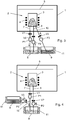
- Fig.2 shows a first embodiment of the apparatus, wherein the apparatus comprises a vacuum chamber 1, an evaporator 2 with a crucible 3 for the liquid metal and an induction coil 4 to further heat and evaporate the liquid metal in the crucible. Above the evaporator passes a strip 5 through the vacuum chamber 1 on which the evaporated metal is applied as a coating.
- crucible 3 Connected to crucible 3 are a supply line 6 and a return line 7 for respectively the supply and return of liquid metal to and from the crucible.
- Supply line 6 and return line 7 are connected to a first vessel, melting pot 8, outside the vacuum chamber.
- a second vessel, feeding pot 9, is provided containing liquid metal connected by means of a feed line 10 to supply line 6. Melting pot 8 and feeding pot 9 are both provided with heating and insulating means 11 which are shown schematically in the drawing.
- the liquid metal from the second vessel 9, the feeding pot is injected outside the vacuum chamber into the supply line between the first vessel 8, the melting pot, and crucible 3. Only two lines are connected to the evaporator 2 through the wall of the vacuum chamber 1. Mixing of the liquid is assured because it is injected in the supply line 6 and due to the mixing in the evaporator 2.
- MHD pumps P1 and P2 are generating the same flow and the flow generated by MHD pump P3 is the same as the evaporation rate of the evaporator.
- the process control is conducted with contactless flow meters in all lines, level sensors in the vessels and the evaporator, the frequency of the induction heater of the evaporator using a Rogowski coil and the measurement of the composition and weight of the produced coating, using for example an X-ray fluorescence (XRF) spectrometer.
- XRF X-ray fluorescence
- the evaporation rate of two elements making up a binary liquid metal is not equal to the composition of the resulting vapour or deposited coating.
- An example is ZnMg, for generating a vapour with 10 wt% Mg and 90wt% Zn the liquid metal in the evaporator must contain approximately 40wt% magnesium and 60wt% Zn. This also means that to produce a coating with a constant composition it is important and necessary that the evaporated material is replenished in such a way that the composition of the liquid metal in the evaporator stays constant. To this aim the composition of the liquid metal from the second vessel 9, the feeding pot, must correspond to the composition of the evaporated material, so the metal liquid from the second vessel 9, the feeding pot, has a different composition than that of the liquid metal in the evaporator.
- This set-up also makes it possible to change the composition of the liquid metal in the evaporator and the produced coating composition.
- First valves V1 and V2 are closed. The evaporation is continued while feeding from the second vessel 9, the feeding pot, only and although this will result in an additional contamination of the evaporator liquid metal, the liquid metal composition in the evaporator can be kept about constant for a certain time.
- the composition in the first vessel 8, the melting pot is changed online to the required composition.
- Valves V1 and V2 are opened and valve V3 is closed. Now the composition in the evaporator is changed due to the feeding from the first vessel 8, the melting pot.
- the MHD pumps P1 and P2 must have a mass flow difference which is the same as the evaporation rate.
- the evaporation is reducing the filling of the melting pot 8 and because the melting pot is much larger than the evaporator the composition will not change significantly in a short time.
- the second vessel 9, the feeding pot, is filled with the new coating composition and valve V3 is opened, and the operation can be continued with the new composition.
- a final embodiment is given in fig.4 .
- the feed line 10 of the second vessel 9, the feeding pot connects to the return line of the first vessel 8, the melting pot.
- This set-up can not be used to change the composition of the deposited coating, while continuing the coating process and controlling the coating composition at the same time. In this case all the valves have to be closed, the melts replaced and then the valves opened up again, first valves V1 and V2, then valve V3.
Landscapes
- Chemical & Material Sciences (AREA)
- Chemical Kinetics & Catalysis (AREA)
- Engineering & Computer Science (AREA)
- Materials Engineering (AREA)
- Mechanical Engineering (AREA)
- Metallurgy (AREA)
- Organic Chemistry (AREA)
- Health & Medical Sciences (AREA)
- Toxicology (AREA)
- Physical Vapour Deposition (AREA)
- Chemical Vapour Deposition (AREA)
Claims (4)
- Procédé pour réguler la composition d'un métal liquide dans un dispositif évaporateur dans une chambre à vide, le métal liquide comprenant au moins deux métaux, le procédé comprenant les étapes consistant à- fournir un métal liquide d'une première composition dans un premier récipient pour un métal liquide,- fournir un métal liquide d'une seconde composition dans un second récipient pour un métal liquide,
caractérisé en ce que le procédé comprend en outre l'étape consistant à amener le métal liquide de la seconde composition au métal liquide du premier récipient ou à l'évaporateur, la composition du métal liquide dans le second récipient étant choisie pour réguler la composition du métal liquide dans l'évaporateur. - Procédé selon la revendication 1, la composition du métal liquide dans le second récipient étant choisie pour compenser l'évaporation des métaux de l'évaporateur.
- Procédé selon la revendication 2, la composition du métal liquide dans le second récipient correspondant à une composition de vapeur prédéfinie.
- Procédé selon la revendication 3, la composition du métal liquide dans le second récipient correspondant à une composition prédéfinie de métal liquide dans le premier récipient.
Priority Applications (1)
| Application Number | Priority Date | Filing Date | Title |
|---|---|---|---|
| EP14793569.6A EP3066229B1 (fr) | 2013-11-05 | 2014-11-05 | Procédé pour réguler la composition de métal liquide dans un dispositif évaporateur |
Applications Claiming Priority (3)
| Application Number | Priority Date | Filing Date | Title |
|---|---|---|---|
| EP13005206 | 2013-11-05 | ||
| EP14793569.6A EP3066229B1 (fr) | 2013-11-05 | 2014-11-05 | Procédé pour réguler la composition de métal liquide dans un dispositif évaporateur |
| PCT/EP2014/073825 WO2015067662A1 (fr) | 2013-11-05 | 2014-11-05 | Procédé et appareil pour réguler la composition de métal liquide dans un dispositif évaporateur |
Publications (2)
| Publication Number | Publication Date |
|---|---|
| EP3066229A1 EP3066229A1 (fr) | 2016-09-14 |
| EP3066229B1 true EP3066229B1 (fr) | 2020-08-26 |
Family
ID=49551497
Family Applications (1)
| Application Number | Title | Priority Date | Filing Date |
|---|---|---|---|
| EP14793569.6A Active EP3066229B1 (fr) | 2013-11-05 | 2014-11-05 | Procédé pour réguler la composition de métal liquide dans un dispositif évaporateur |
Country Status (7)
| Country | Link |
|---|---|
| US (1) | US10131983B2 (fr) |
| EP (1) | EP3066229B1 (fr) |
| JP (1) | JP6430528B2 (fr) |
| KR (1) | KR102242070B1 (fr) |
| CN (1) | CN105793464B (fr) |
| ES (1) | ES2817842T3 (fr) |
| WO (1) | WO2015067662A1 (fr) |
Families Citing this family (6)
| Publication number | Priority date | Publication date | Assignee | Title |
|---|---|---|---|---|
| EP3452631B1 (fr) | 2016-05-03 | 2020-03-25 | Tata Steel Nederland Technology B.V. | Procédé d'exploitation d'un appareil destiné à alimenter un dispositif évaporateur en métal liquide |
| AU2017260147B2 (en) * | 2016-05-03 | 2022-08-25 | Tata Steel Nederland Technology B.V. | Apparatus for feeding a liquid material to an evaporator device |
| EP3452632B1 (fr) * | 2016-05-03 | 2020-07-08 | Tata Steel Nederland Technology B.V. | Procédé de régulation de température de pompe électromagnétique |
| WO2018020296A1 (fr) * | 2016-07-27 | 2018-02-01 | Arcelormittal | Appareil et procédé de dépôt par évaporation sous vide |
| KR102098455B1 (ko) * | 2017-12-26 | 2020-04-07 | 주식회사 포스코 | 연속 증착 장치 및 연속 증착 방법 |
| JP7250614B2 (ja) * | 2019-05-17 | 2023-04-03 | 株式会社アルバック | スパッタリング装置 |
Family Cites Families (14)
| Publication number | Priority date | Publication date | Assignee | Title |
|---|---|---|---|---|
| JPH02125866A (ja) * | 1988-11-04 | 1990-05-14 | Kobe Steel Ltd | 合金蒸着めっき装置 |
| JPH07145473A (ja) * | 1993-11-24 | 1995-06-06 | Kobe Steel Ltd | 蒸着合金めっき法 |
| EP1174526A1 (fr) * | 2000-07-17 | 2002-01-23 | Nederlandse Organisatie voor Toegepast Natuurwetenschappelijk Onderzoek TNO | Dépôt sous vide en continu |
| KR20070015923A (ko) * | 2004-05-27 | 2007-02-06 | 시드라베, 인크. | 금속 및 금속 합금을 증발시키기 위한 진공 증착 방법 및장치 |
| LV13383B (en) * | 2004-05-27 | 2006-02-20 | Sidrabe As | Method and device for vacuum vaporization metals or alloys |
| JP4570403B2 (ja) * | 2004-06-28 | 2010-10-27 | 日立造船株式会社 | 蒸発装置、蒸着装置および蒸着装置における蒸発装置の切替方法 |
| DE112007002897A5 (de) * | 2006-09-29 | 2009-09-03 | Von Ardenne Anlagentechnik Gmbh | Vakuumbeschichtungsverfahren und Anordnung zur Durchführung des Verfahrens |
| EP1972699A1 (fr) * | 2007-03-20 | 2008-09-24 | ArcelorMittal France | Procede de revetement d'un substrat et installation de depot sous vide d'alliage metallique |
| EP2048261A1 (fr) * | 2007-10-12 | 2009-04-15 | ArcelorMittal France | Générateur de vapeur industriel pour le dépôt d'un revêtement d'alliage sur une bande métallique |
| EP2199425A1 (fr) * | 2008-12-18 | 2010-06-23 | ArcelorMittal France | Générateur de vapeur industriel pour le dépôt d'un revêtement d'alliage sur une bande métallique (II) |
| KR101639811B1 (ko) | 2009-09-28 | 2016-07-15 | 주식회사 포스코 | 용융금속 공급장치 |
| US20110195187A1 (en) * | 2010-02-10 | 2011-08-11 | Apple Inc. | Direct liquid vaporization for oleophobic coatings |
| EP2663665B1 (fr) * | 2011-01-14 | 2015-03-11 | Arcelormittal Investigacion y Desarrollo | Dispositif d'alimentation automatique d'un generateur de vapeur metallique industriel |
| AU2013242397B2 (en) * | 2012-03-30 | 2017-06-15 | Posco | Method and apparatus for feeding liquid metal to an evaporator device |
-
2014
- 2014-11-05 WO PCT/EP2014/073825 patent/WO2015067662A1/fr not_active Ceased
- 2014-11-05 EP EP14793569.6A patent/EP3066229B1/fr active Active
- 2014-11-05 KR KR1020167014279A patent/KR102242070B1/ko not_active Expired - Fee Related
- 2014-11-05 CN CN201480065819.4A patent/CN105793464B/zh not_active Expired - Fee Related
- 2014-11-05 ES ES14793569T patent/ES2817842T3/es active Active
- 2014-11-05 US US15/032,572 patent/US10131983B2/en active Active
- 2014-11-05 JP JP2016551043A patent/JP6430528B2/ja active Active
Non-Patent Citations (1)
| Title |
|---|
| None * |
Also Published As
| Publication number | Publication date |
|---|---|
| ES2817842T3 (es) | 2021-04-08 |
| CN105793464B (zh) | 2018-01-02 |
| EP3066229A1 (fr) | 2016-09-14 |
| US10131983B2 (en) | 2018-11-20 |
| KR20160082523A (ko) | 2016-07-08 |
| JP2016535173A (ja) | 2016-11-10 |
| CN105793464A (zh) | 2016-07-20 |
| WO2015067662A1 (fr) | 2015-05-14 |
| KR102242070B1 (ko) | 2021-04-20 |
| US20160265102A1 (en) | 2016-09-15 |
| JP6430528B2 (ja) | 2018-11-28 |
Similar Documents
| Publication | Publication Date | Title |
|---|---|---|
| EP3066229B1 (fr) | Procédé pour réguler la composition de métal liquide dans un dispositif évaporateur | |
| Mereddy et al. | Grain refinement of wire arc additively manufactured titanium by the addition of silicon | |
| JP6313746B2 (ja) | 液体金属を蒸発器に供給する方法および装置 | |
| Wang et al. | Phase constituent control and correlated properties of titanium aluminide intermetallic alloys through dual-wire arc additive manufacturing | |
| US20220228252A1 (en) | Apparatus and Method for Vacuum Deposition | |
| CN101855380A (zh) | 用于在金属带上沉积合金镀膜的工业蒸汽发生器 | |
| KR20130119107A (ko) | 증착장치 | |
| Leijon et al. | A novel rapid alloy development method towards powder bed additive manufacturing, demonstrated for binary Al-Ti,-Zr and-Nb alloys | |
| CN102257175A (zh) | 用于在金属带上沉积合金涂层的工业蒸汽发生器(ii) | |
| Zeng et al. | Enhanced Grain Refining Effect of Mg–Zr Master Alloy on Magnesium Alloys via a Synergistic Strategy Involving Heterogeneous Nucleation and Solute-Driven Growth Restriction | |
| Tan et al. | Grain refinement of primary Cu6Sn5 in the Sn-3wt% Ag-5wt% Cu alloy by Ge | |
| Vutova et al. | Influence of process parameters on the metal quality at electron beam melting of molybdenum | |
| Zhou et al. | Premelting behavior and interfacial reaction of the Sn/Cu and Sn/Ag soldering systems during the reflow process | |
| Yan et al. | The mechanisms for removing O, N, C and metal impurities in the purification of tungsten by electron beam smelting | |
| Hou et al. | Liquid phase separation microstructure and properties of mixed Cu-Sn and Co-base alloys without or with molybdenum addition processed by plasma transferred arc hardfacing | |
| JP2019521256A (ja) | 二段階の溶解及び鋳造のシステム及び方法 | |
| JPH07110967B2 (ja) | 蒸気凝縮による合金の製造において、蒸発浴中の充填物金属を補充する方法及び該方法に用いる装置 | |
| KR20190075733A (ko) | 고휘발성 원소의 표준 시료 제조 장치 및 방법 | |
| WO2007045215A1 (fr) | Procede et dispositif d'evaporation de matiere destines a des revetements | |
| RU2674178C2 (ru) | Получение высококачественного марганца из ферромарганца испарением в вакуумной индукционной установке | |
| Yu et al. | Study on the Strengthening of Unfavorable Composition Zones in 316L‐IN625 Functional Gradient Materials by Nb Element | |
| EP4155010A1 (fr) | Alliage de compositions de projection de métal et procédés associés | |
| US20070160775A1 (en) | Physical vapor deposition process and apparatus therefor | |
| Liu et al. | Mechanism and kinetics of volatile impurity removal during preparation of high-purity gadolinium via hydrogen plasma zone melting: A novel numerical model for predicting impurity redistribution | |
| Yang et al. | Orientation evolution of single-crystal superalloys under different solidification interface |
Legal Events
| Date | Code | Title | Description |
|---|---|---|---|
| PUAI | Public reference made under article 153(3) epc to a published international application that has entered the european phase |
Free format text: ORIGINAL CODE: 0009012 |
|
| 17P | Request for examination filed |
Effective date: 20160606 |
|
| AK | Designated contracting states |
Kind code of ref document: A1 Designated state(s): AL AT BE BG CH CY CZ DE DK EE ES FI FR GB GR HR HU IE IS IT LI LT LU LV MC MK MT NL NO PL PT RO RS SE SI SK SM TR |
|
| AX | Request for extension of the european patent |
Extension state: BA ME |
|
| DAX | Request for extension of the european patent (deleted) | ||
| STAA | Information on the status of an ep patent application or granted ep patent |
Free format text: STATUS: EXAMINATION IS IN PROGRESS |
|
| 17Q | First examination report despatched |
Effective date: 20180703 |
|
| REG | Reference to a national code |
Ref country code: DE Ref legal event code: R079 Ref document number: 602014069448 Country of ref document: DE Free format text: PREVIOUS MAIN CLASS: C23C0014240000 Ipc: C23C0014140000 |
|
| RIC1 | Information provided on ipc code assigned before grant |
Ipc: C23C 14/24 20060101ALI20200304BHEP Ipc: C23C 14/14 20060101AFI20200304BHEP Ipc: B01D 1/00 20060101ALI20200304BHEP |
|
| GRAP | Despatch of communication of intention to grant a patent |
Free format text: ORIGINAL CODE: EPIDOSNIGR1 |
|
| STAA | Information on the status of an ep patent application or granted ep patent |
Free format text: STATUS: GRANT OF PATENT IS INTENDED |
|
| INTG | Intention to grant announced |
Effective date: 20200520 |
|
| GRAS | Grant fee paid |
Free format text: ORIGINAL CODE: EPIDOSNIGR3 |
|
| GRAA | (expected) grant |
Free format text: ORIGINAL CODE: 0009210 |
|
| STAA | Information on the status of an ep patent application or granted ep patent |
Free format text: STATUS: THE PATENT HAS BEEN GRANTED |
|
| AK | Designated contracting states |
Kind code of ref document: B1 Designated state(s): AL AT BE BG CH CY CZ DE DK EE ES FI FR GB GR HR HU IE IS IT LI LT LU LV MC MK MT NL NO PL PT RO RS SE SI SK SM TR |
|
| REG | Reference to a national code |
Ref country code: GB Ref legal event code: FG4D |
|
| REG | Reference to a national code |
Ref country code: CH Ref legal event code: EP |
|
| REG | Reference to a national code |
Ref country code: AT Ref legal event code: REF Ref document number: 1306448 Country of ref document: AT Kind code of ref document: T Effective date: 20200915 |
|
| REG | Reference to a national code |
Ref country code: IE Ref legal event code: FG4D |
|
| REG | Reference to a national code |
Ref country code: DE Ref legal event code: R096 Ref document number: 602014069448 Country of ref document: DE |
|
| REG | Reference to a national code |
Ref country code: LT Ref legal event code: MG4D |
|
| PG25 | Lapsed in a contracting state [announced via postgrant information from national office to epo] |
Ref country code: HR Free format text: LAPSE BECAUSE OF FAILURE TO SUBMIT A TRANSLATION OF THE DESCRIPTION OR TO PAY THE FEE WITHIN THE PRESCRIBED TIME-LIMIT Effective date: 20200826 Ref country code: LT Free format text: LAPSE BECAUSE OF FAILURE TO SUBMIT A TRANSLATION OF THE DESCRIPTION OR TO PAY THE FEE WITHIN THE PRESCRIBED TIME-LIMIT Effective date: 20200826 Ref country code: GR Free format text: LAPSE BECAUSE OF FAILURE TO SUBMIT A TRANSLATION OF THE DESCRIPTION OR TO PAY THE FEE WITHIN THE PRESCRIBED TIME-LIMIT Effective date: 20201127 Ref country code: NO Free format text: LAPSE BECAUSE OF FAILURE TO SUBMIT A TRANSLATION OF THE DESCRIPTION OR TO PAY THE FEE WITHIN THE PRESCRIBED TIME-LIMIT Effective date: 20201126 Ref country code: BG Free format text: LAPSE BECAUSE OF FAILURE TO SUBMIT A TRANSLATION OF THE DESCRIPTION OR TO PAY THE FEE WITHIN THE PRESCRIBED TIME-LIMIT Effective date: 20201126 Ref country code: FI Free format text: LAPSE BECAUSE OF FAILURE TO SUBMIT A TRANSLATION OF THE DESCRIPTION OR TO PAY THE FEE WITHIN THE PRESCRIBED TIME-LIMIT Effective date: 20200826 Ref country code: PT Free format text: LAPSE BECAUSE OF FAILURE TO SUBMIT A TRANSLATION OF THE DESCRIPTION OR TO PAY THE FEE WITHIN THE PRESCRIBED TIME-LIMIT Effective date: 20201228 Ref country code: SE Free format text: LAPSE BECAUSE OF FAILURE TO SUBMIT A TRANSLATION OF THE DESCRIPTION OR TO PAY THE FEE WITHIN THE PRESCRIBED TIME-LIMIT Effective date: 20200826 |
|
| REG | Reference to a national code |
Ref country code: NL Ref legal event code: MP Effective date: 20200826 |
|
| REG | Reference to a national code |
Ref country code: AT Ref legal event code: MK05 Ref document number: 1306448 Country of ref document: AT Kind code of ref document: T Effective date: 20200826 |
|
| PG25 | Lapsed in a contracting state [announced via postgrant information from national office to epo] |
Ref country code: NL Free format text: LAPSE BECAUSE OF FAILURE TO SUBMIT A TRANSLATION OF THE DESCRIPTION OR TO PAY THE FEE WITHIN THE PRESCRIBED TIME-LIMIT Effective date: 20200826 Ref country code: LV Free format text: LAPSE BECAUSE OF FAILURE TO SUBMIT A TRANSLATION OF THE DESCRIPTION OR TO PAY THE FEE WITHIN THE PRESCRIBED TIME-LIMIT Effective date: 20200826 Ref country code: RS Free format text: LAPSE BECAUSE OF FAILURE TO SUBMIT A TRANSLATION OF THE DESCRIPTION OR TO PAY THE FEE WITHIN THE PRESCRIBED TIME-LIMIT Effective date: 20200826 Ref country code: PL Free format text: LAPSE BECAUSE OF FAILURE TO SUBMIT A TRANSLATION OF THE DESCRIPTION OR TO PAY THE FEE WITHIN THE PRESCRIBED TIME-LIMIT Effective date: 20200826 Ref country code: IS Free format text: LAPSE BECAUSE OF FAILURE TO SUBMIT A TRANSLATION OF THE DESCRIPTION OR TO PAY THE FEE WITHIN THE PRESCRIBED TIME-LIMIT Effective date: 20201226 |
|
| REG | Reference to a national code |
Ref country code: ES Ref legal event code: FG2A Ref document number: 2817842 Country of ref document: ES Kind code of ref document: T3 Effective date: 20210408 |
|
| PG25 | Lapsed in a contracting state [announced via postgrant information from national office to epo] |
Ref country code: DK Free format text: LAPSE BECAUSE OF FAILURE TO SUBMIT A TRANSLATION OF THE DESCRIPTION OR TO PAY THE FEE WITHIN THE PRESCRIBED TIME-LIMIT Effective date: 20200826 Ref country code: CZ Free format text: LAPSE BECAUSE OF FAILURE TO SUBMIT A TRANSLATION OF THE DESCRIPTION OR TO PAY THE FEE WITHIN THE PRESCRIBED TIME-LIMIT Effective date: 20200826 Ref country code: EE Free format text: LAPSE BECAUSE OF FAILURE TO SUBMIT A TRANSLATION OF THE DESCRIPTION OR TO PAY THE FEE WITHIN THE PRESCRIBED TIME-LIMIT Effective date: 20200826 Ref country code: RO Free format text: LAPSE BECAUSE OF FAILURE TO SUBMIT A TRANSLATION OF THE DESCRIPTION OR TO PAY THE FEE WITHIN THE PRESCRIBED TIME-LIMIT Effective date: 20200826 Ref country code: SM Free format text: LAPSE BECAUSE OF FAILURE TO SUBMIT A TRANSLATION OF THE DESCRIPTION OR TO PAY THE FEE WITHIN THE PRESCRIBED TIME-LIMIT Effective date: 20200826 |
|
| REG | Reference to a national code |
Ref country code: DE Ref legal event code: R097 Ref document number: 602014069448 Country of ref document: DE |
|
| PG25 | Lapsed in a contracting state [announced via postgrant information from national office to epo] |
Ref country code: AT Free format text: LAPSE BECAUSE OF FAILURE TO SUBMIT A TRANSLATION OF THE DESCRIPTION OR TO PAY THE FEE WITHIN THE PRESCRIBED TIME-LIMIT Effective date: 20200826 Ref country code: AL Free format text: LAPSE BECAUSE OF FAILURE TO SUBMIT A TRANSLATION OF THE DESCRIPTION OR TO PAY THE FEE WITHIN THE PRESCRIBED TIME-LIMIT Effective date: 20200826 |
|
| PG25 | Lapsed in a contracting state [announced via postgrant information from national office to epo] |
Ref country code: MC Free format text: LAPSE BECAUSE OF FAILURE TO SUBMIT A TRANSLATION OF THE DESCRIPTION OR TO PAY THE FEE WITHIN THE PRESCRIBED TIME-LIMIT Effective date: 20200826 Ref country code: SK Free format text: LAPSE BECAUSE OF FAILURE TO SUBMIT A TRANSLATION OF THE DESCRIPTION OR TO PAY THE FEE WITHIN THE PRESCRIBED TIME-LIMIT Effective date: 20200826 |
|
| REG | Reference to a national code |
Ref country code: CH Ref legal event code: PL |
|
| PLBE | No opposition filed within time limit |
Free format text: ORIGINAL CODE: 0009261 |
|
| STAA | Information on the status of an ep patent application or granted ep patent |
Free format text: STATUS: NO OPPOSITION FILED WITHIN TIME LIMIT |
|
| PG25 | Lapsed in a contracting state [announced via postgrant information from national office to epo] |
Ref country code: LU Free format text: LAPSE BECAUSE OF NON-PAYMENT OF DUE FEES Effective date: 20201105 |
|
| 26N | No opposition filed |
Effective date: 20210527 |
|
| PG25 | Lapsed in a contracting state [announced via postgrant information from national office to epo] |
Ref country code: SI Free format text: LAPSE BECAUSE OF FAILURE TO SUBMIT A TRANSLATION OF THE DESCRIPTION OR TO PAY THE FEE WITHIN THE PRESCRIBED TIME-LIMIT Effective date: 20200826 Ref country code: LI Free format text: LAPSE BECAUSE OF NON-PAYMENT OF DUE FEES Effective date: 20201130 Ref country code: CH Free format text: LAPSE BECAUSE OF NON-PAYMENT OF DUE FEES Effective date: 20201130 |
|
| PG25 | Lapsed in a contracting state [announced via postgrant information from national office to epo] |
Ref country code: IE Free format text: LAPSE BECAUSE OF NON-PAYMENT OF DUE FEES Effective date: 20201105 |
|
| PGFP | Annual fee paid to national office [announced via postgrant information from national office to epo] |
Ref country code: GB Payment date: 20211129 Year of fee payment: 8 |
|
| PG25 | Lapsed in a contracting state [announced via postgrant information from national office to epo] |
Ref country code: TR Free format text: LAPSE BECAUSE OF FAILURE TO SUBMIT A TRANSLATION OF THE DESCRIPTION OR TO PAY THE FEE WITHIN THE PRESCRIBED TIME-LIMIT Effective date: 20200826 Ref country code: MT Free format text: LAPSE BECAUSE OF FAILURE TO SUBMIT A TRANSLATION OF THE DESCRIPTION OR TO PAY THE FEE WITHIN THE PRESCRIBED TIME-LIMIT Effective date: 20200826 Ref country code: CY Free format text: LAPSE BECAUSE OF FAILURE TO SUBMIT A TRANSLATION OF THE DESCRIPTION OR TO PAY THE FEE WITHIN THE PRESCRIBED TIME-LIMIT Effective date: 20200826 |
|
| PG25 | Lapsed in a contracting state [announced via postgrant information from national office to epo] |
Ref country code: MK Free format text: LAPSE BECAUSE OF FAILURE TO SUBMIT A TRANSLATION OF THE DESCRIPTION OR TO PAY THE FEE WITHIN THE PRESCRIBED TIME-LIMIT Effective date: 20200826 |
|
| P01 | Opt-out of the competence of the unified patent court (upc) registered |
Effective date: 20230517 |
|
| GBPC | Gb: european patent ceased through non-payment of renewal fee |
Effective date: 20221105 |
|
| PG25 | Lapsed in a contracting state [announced via postgrant information from national office to epo] |
Ref country code: GB Free format text: LAPSE BECAUSE OF NON-PAYMENT OF DUE FEES Effective date: 20221105 |
|
| PGFP | Annual fee paid to national office [announced via postgrant information from national office to epo] |
Ref country code: DE Payment date: 20241127 Year of fee payment: 11 |
|
| PGFP | Annual fee paid to national office [announced via postgrant information from national office to epo] |
Ref country code: BE Payment date: 20241127 Year of fee payment: 11 |
|
| PGFP | Annual fee paid to national office [announced via postgrant information from national office to epo] |
Ref country code: FR Payment date: 20241126 Year of fee payment: 11 |
|
| PGFP | Annual fee paid to national office [announced via postgrant information from national office to epo] |
Ref country code: IT Payment date: 20241122 Year of fee payment: 11 Ref country code: ES Payment date: 20241202 Year of fee payment: 11 |