EP3067246A1 - Vorrichtung und Verfahren zur Überwachung der Funktionsfähigkeit einer Signalverbindung - Google Patents
Vorrichtung und Verfahren zur Überwachung der Funktionsfähigkeit einer Signalverbindung Download PDFInfo
- Publication number
- EP3067246A1 EP3067246A1 EP15158135.2A EP15158135A EP3067246A1 EP 3067246 A1 EP3067246 A1 EP 3067246A1 EP 15158135 A EP15158135 A EP 15158135A EP 3067246 A1 EP3067246 A1 EP 3067246A1
- Authority
- EP
- European Patent Office
- Prior art keywords
- signal
- monitoring
- connecting cable
- current
- balise
- Prior art date
- Legal status (The legal status is an assumption and is not a legal conclusion. Google has not performed a legal analysis and makes no representation as to the accuracy of the status listed.)
- Granted
Links
Images
Classifications
-
- B—PERFORMING OPERATIONS; TRANSPORTING
- B61—RAILWAYS
- B61L—GUIDING RAILWAY TRAFFIC; ENSURING THE SAFETY OF RAILWAY TRAFFIC
- B61L3/00—Devices along the route for controlling devices on the vehicle or train, e.g. to release brake or to operate a warning signal
- B61L3/02—Devices along the route for controlling devices on the vehicle or train, e.g. to release brake or to operate a warning signal at selected places along the route, e.g. intermittent control simultaneous mechanical and electrical control
- B61L3/08—Devices along the route for controlling devices on the vehicle or train, e.g. to release brake or to operate a warning signal at selected places along the route, e.g. intermittent control simultaneous mechanical and electrical control controlling electrically
- B61L3/12—Devices along the route for controlling devices on the vehicle or train, e.g. to release brake or to operate a warning signal at selected places along the route, e.g. intermittent control simultaneous mechanical and electrical control controlling electrically using magnetic or electrostatic induction; using radio waves
- B61L3/121—Devices along the route for controlling devices on the vehicle or train, e.g. to release brake or to operate a warning signal at selected places along the route, e.g. intermittent control simultaneous mechanical and electrical control controlling electrically using magnetic or electrostatic induction; using radio waves using magnetic induction
-
- B—PERFORMING OPERATIONS; TRANSPORTING
- B61—RAILWAYS
- B61L—GUIDING RAILWAY TRAFFIC; ENSURING THE SAFETY OF RAILWAY TRAFFIC
- B61L27/00—Central railway traffic control systems; Trackside control; Communication systems specially adapted therefor
- B61L27/50—Trackside diagnosis or maintenance, e.g. software upgrades
- B61L27/53—Trackside diagnosis or maintenance, e.g. software upgrades for trackside elements or systems, e.g. trackside supervision of trackside control system conditions
Definitions
- the invention relates to a device and a method for monitoring the operability of signal connection between a control unit and a balise.
- an interlocking computer or interlocking control unit controls and monitors various devices along a railway line in modern railway signalling systems.
- point machines and lamp signals are important wayside objects.
- lamp signals have been monitored by the interlocking control unit by measuring the current which flows through the lamp and checking if said current is within predetermined limits. If the lamp fails, the failure will affect the current and can thus be detected by the interlocking control unit which, in turn, generates an alarm signal.
- the current deliverance to a point machine can be measured and monitored and the status of the point machine can be monitored depending on said current. Should the point machine fail, the failure will be detected when the point machine is ordered to reverse and an alarm signal can be generated.
- Track-sided transmitters which can be also referred to as balises, which are used to send information to passing trains, cannot be monitored in this way. If, for instance, a cable connecting the balise and a balise-related control unit breaks, the failure is not automatically detected by the control unit. Similarly, if the balise should fail or be ripped off its sleeper, the control unit will not detect it. Furthermore, cable breakage or failure of the balise will result in restrictive action by the rail vehicles but it is not always clear that something is broken or missing. The driver of the rail vehicle is supposed to report failures of the balise but such reports are usually irregular.
- the document DE 10 2009 012 986 A1 describes a method for operating a system for controlling a rail vehicle.
- a track-sided electronic control unit selects a data signal depending on a signal term and transmits said signal to a balise which is arranged on a track. Furthermore, the balise receives an activation signal which is sent by a vehicle-sided antenna.
- EP 13193300.4 discloses a method for monitoring the operability of a balise for transmitting information to a rail vehicle, wherein a tele-powering signal emitted by the rail vehicle is received by the balise, wherein a telegram switch inhibit signal is generated by the balise and transmitted to a balise-related control unit upon reception of the tele-powering signal, wherein the operability of the balise is monitored depending on the telegram switch inhibit signal.
- the disadvantage of the method disclosed in said document is that the control unit needs to be switched on and a train has to pass the balise.
- a device for monitoring the operability of a signal connection between a control unit and a balise is proposed.
- a balise denotes a device by which a signal encoding or containing balise-related information can be transmitted to a vehicle passing the balise.
- the balise-related information can e.g. comprise static information which are always transmitted to a vehicle passing the balise. Static information can thus be also transmitted if no data is provided to the balise by the control unit. Static information can be information on an identity of the balise, information on a geographical position of the balise and information on one or more consecutive balises along a track of the rail vehicle. Further, a physical representation of said information can be provided within the balise. For instance, data encoding the static information can be programmed into a non-volatile memory of the balise.
- a dynamic information can e.g. be an information on a movement authorization.
- a movement authorization information can e.g. represent if vehicle passage of the balise is allowed or not permitted.
- the movement authorization can be determined based on the state of a signal lamp and/or point machine which is/are assigned to the balise. If the signal lamp or point machine is in a first state, the vehicle passage is allowed. If the signal lamp or point machine is in a second state, the vehicle passage is not permitted.
- the control unit (which can also be referred to as balise-related control unit) can e.g.
- control unit can be connected to the signal lamp and/or to an interlocking control unit for controlling the operation of the signal lamp in order to determine the state of the signal lamp.
- control unit can be connected to the signal lamp, wherein an operating current of the signal lamp is determinable by the control unit. Depending on said operating current, the control unit can determine whether the signal lamp is in the aforementioned first or second state and generate a corresponding operating signal which is than transmitted to the balise via the signal connection.
- An information if a static and/or dynamic information and, if applicable, an information on which dynamic information is to be transmitted by the balise can be provided by the control unit and transmitted from the control unit to the balise via an operating signal. It is for instance, possible that a physical representation of a dynamic information, e.g. if the signal lamp is in the first or in the second state, is provided within the balise, wherein the control unit provides an information on which of the first and the second signal is to be transmitted to a passing vehicle.
- the signal connection is provided at least partially by at least one connecting cable. It is possible that an operating signal output terminal of the control unit is connected to the connecting cable non-galvanically. In particular, the at least one operating signal output terminal can be connected to the connecting cable via transformer. It is further possible that an operating signal input terminal of the balise is connected to the connecting cable non-galvanically, in particular via another transformer.
- Monitoring the operability of the signal connection comprises in particular monitoring the presence of the connecting cable, the presence of the balise and monitoring the integrity of the connecting cable.
- the control unit can in particular be provided by a so-called lineside electronic unit (LEU).
- the proposed device comprises a monitoring signal generator.
- the monitoring signal generator can be an alternating current (AC) signal generator.
- the device comprises at least one means for determining a connecting cable current.
- the at least one means for determining the connecting cable current can be a means for measuring the current, in particular a current sensor.
- the device comprises at least one evaluating unit.
- the evaluating unit can be connected to the at least one means for determining the connecting cable current.
- a monitoring signal with a monitoring frequency is injectable into the connecting cable.
- the term “able” is used in the sense of "can be”. This means that the proposed device is arranged and/or designed such that it is capable of performing the corresponding action.
- the monitoring signal can be injected simultaneously to an operating signal.
- the monitoring signal can be injected in a time period during which no operating signal is transmitted via the connecting cable. It is possible that the monitoring signal can be exclusively injected simultaneously to an operating signal or exclusively injected in a time period during which no operating signal is transmitted via the connecting cable.
- the monitoring signal is injectable independent of the transmission of an operating signal.
- the monitoring signal can be injected by the aforementioned monitoring signal generator or an injection means.
- connecting cable current is determinable, in particular by the aforementioned means for determining the connecting cable current.
- a current portion with the monitoring frequency is determinable, in particular by the at least one evaluating unit.
- the current portion with the monitoring frequency can e.g. denote a spectral portion of the cable current spectrum which comprises (only) the monitoring frequency or frequencies within an (small) interval around the monitoring frequency.
- an incorrect operability of the signal connection is detectable if a current value of the current portion is smaller than a predetermined threshold value.
- the current value can e.g. be a root mean square (RMS) value or an amplitude of the current portion.
- the current value can be an intensity of the aforementioned spectral portion.
- the predetermined threshold value can be determined application-dependent by a skilled person. In particular the predetermined threshold value is small, preferably close to zero.
- a correct operability of the signal connection is detectable if the current value of the current portion is higher than or equal to the predetermined threshold value.
- the monitoring signal is most likely not received by the balise. This can be the case if the connecting cable is stolen, broken and/or if the balise is not connected to the connecting cable. As the injection of the monitoring signal is theoretically possible at all-time instances, a time-related applicability of the monitoring method is increased.
- the device further comprises at least one means for injecting the monitoring signal non-galvanically into the connecting cable. This means that there is no galvanic connection between the connecting cable and the monitoring signal generator. This advantageously reduces the risk of a cross-talk between two balises and further increases an EMI-robustness of the connecting cable, the monitoring signal generator and the corresponding signal connection.
- the at least one means for injecting monitoring signal is a transformer.
- the transformer can be the same transformer by which the aforementioned at least one operating signal output terminal of the control unit is connected to the connecting cable. It is, however, also possible that the transformer is provided separately from said transformer connecting the at least one monitoring signal output terminal to the connecting cable.
- the use of a transformer advantageously allows a reliable injection of the monitoring signal.
- the monitoring frequency is lower than an operating frequency of an operating signal which is transmitted from the control unit to the balise via the signal connection.
- the operating signal has been explained before.
- the operating signal is an AC signal typically comprises a frequency of a range from 10 kHz to 1000 kHz, in particular from 50 kHz to 600 kHz.
- An impedance of the signal connection, in particular of the connecting cable, for the operating frequency is high.
- a current-based monitoring of the operability therefore requires a monitoring frequency of the injected monitoring signal which is chosen depending on an impedance of the signal connection such that a non-zero current can flow throw through the connecting cable.
- the monitoring frequency can be chosen from a range of 90 Hz to 110 Hz. This advantageously increases a reliability of the monitoring process.
- the monitoring frequency is chosen unequal to 50 Hz. Alternatively or in addition, the monitoring frequency is chosen unequal to 60 Hz. Alternatively or in addition, the monitoring frequency is chosen unequal to 1 or more corresponding overtones of 50 Hz and/or 60 Hz. Alternatively or in addition, the monitoring frequency is chosen unequal to 1 or more corresponding undertones of 50 Hz and/or 60 Hz, e.g. unequal to 50/3 Hz (16 2/3 Hz). As the stated frequencies are often use in devices arranged in the vicinity of the signal connection, a monitoring signal with one of said frequencies can be disturbed. Thus, the described embodiment further increases a reliability of the monitoring process.
- the monitoring signal is injectable during an operating signal is transmitted via the signal connection.
- both, the operating signal and the monitoring signal are applied to the signal connection.
- the proposed device can be used during time periods where no operating signal is applied to the signal connection and also in time periods during which an operating signal is applied to the signal connection.
- the monitoring signal is superimposable onto the operating signal.
- the aforementioned monitoring signal generator and/or the at least one means for injecting the monitoring signal can be designed and/or arranged such that the monitoring signal can be superimposed onto the operating signal. This advantageously simplifies a simultaneous transmission of the operating and monitoring signal.
- an alarm signal is generable if an incorrect operability is detected.
- the alarm signal can e.g. be generated by the aforementioned evaluating unit.
- the alarm signal can be transmitted to an external control unit, e.g. the interlocking control unit.
- the proposed device can comprise at least one signal transmission means.
- the alarm signal can be transmitted using a predetermined communication protocol, in particular in form of a data stream.
- a supervised switch is activatable if an incorrect operability is detected.
- the switch can e.g. be supervised by a supervising unit.
- a supervising unit can e.g. be provided by the aforementioned interlocking control unit.
- the alarm signal can be generated by the supervising unit.
- the alarm signal can also be provided to operating personal via adequate means.
- the operating personal can be immediately informed in the case that the connecting cable is stolen, broken and/or a balise is not connected to the connecting cable anymore. Then, adequate counter measures can be taken.
- the device can comprise at least one filter means.
- Filter means can e.g. be designed as a low-pass filter or a band-pass filter or a notch filter. This advantageously allows a reliable determination of the current portion with a monitoring frequency in particular in the case if an operating signal is transmitted via the signal connection simultaneously.
- the monitoring signal generator and/or the at least one means for measuring a connecting cable current and/or the at least one evaluating unit is provided by the control unit.
- the monitoring signal generator and/or the at least one means for measuring a connecting cable current and/or the at least one evaluating unit is provided by at least one unit which is build separate from the control unit.
- a signal connection is provided at least partially by at least one connecting cable.
- a monitoring signal with a monitoring frequency is injected into the connecting cable. Further, a connecting cable current is determined, in particular measured. Further, a current portion with a monitoring frequency is determined. An incorrect operability of this signal connection is detected if a current value of the current portion is smaller than a predetermined threshold value. A correct operability of the signal connection can be detected if the current value of the current portion is higher than or equal to the predetermined threshold value.
- the proposed method By performing the proposed method, a reliable monitoring of the operability is possible, wherein a time-related applicability of the method is increased.
- the method can be performed at all times.
- the monitoring signal is injected non-galvanically. This has been explained before.
- monitoring signal is injected via a transformer. This has been also explained before.
- the monitoring frequency is lower than an operating frequency of an operating signal which is transmitted from the control unit to the balise via the signal connection.
- the monitoring frequency is chosen unequal to 50 Hz and/or unequal to 60 Hz and/or unequal to 1 or more corresponding overtones and/or undertones.
- the monitoring signal is injected during an operating signal is transmitted via the signal connection.
- the monitoring signal is superimposed onto the operating signal.
- an alarm signal is generated and/or a supervised switch is activated if an incorrect operability is detected.
- the determined connecting cable current is filtered in order to determine the current portion with the monitoring frequency.
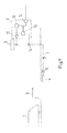
- FIG. 1 shows a rail vehicle 1 travelling along a rail track 2, wherein a direction of travel indicated by an arrow 3. Further shown is a balise 4 for transmitting a signal which is received by the rail vehicle 1.
- the balise 4 is connected to a lineside electronic unit 5 (LEU 5) via a balise-sided transformer 6, a connecting cable 7 and a LEU-sided transformer (not shown).
- the LEU-sided transformer can be part of the LEU 5.
- a connecting cable current I is also indicated in figure 1 .
- the device 9 comprises a monitoring signal generator 10.
- the monitoring signal generator 10 generates a monitoring signal with a monitoring frequency which is lower than an operating frequency of an operating signal generated by the control unit 5.
- the monitoring signal is injected into the connecting cable 7 via a generator-sited transformer 11.
- the device comprises a current sensor 12 for measuring the connecting cable current I.
- the current sensor 12 is connected to an evaluating unit 13, wherein an evaluating unit 13 of the device 9 can determine a current value of the current portion of the connecting cable current I with the monitoring frequency.
- the current portion with the monitoring frequency denotes a portion of the cable current I which is generated due to the injected monitoring signal.
- the evaluating unit 13 can be connected to the signal generator 10.
- the device 9 comprises a signal communication means 14 which also connected to the evaluating unit 13.
- An incorrect operability of the signal connection is detectable if current value of a current portion of the measured cable current I is smaller than a predetermined threshold value.
- an alarm signal can be generated by the evaluating unit 13 and transmitted via the transmitting means to an external higher-level system, e.g. an interlocking control unit.
Landscapes
- Engineering & Computer Science (AREA)
- Mechanical Engineering (AREA)
- Health & Medical Sciences (AREA)
- Biomedical Technology (AREA)
- General Health & Medical Sciences (AREA)
- Alarm Systems (AREA)
- Train Traffic Observation, Control, And Security (AREA)
- Testing Of Short-Circuits, Discontinuities, Leakage, Or Incorrect Line Connections (AREA)
Priority Applications (5)
| Application Number | Priority Date | Filing Date | Title |
|---|---|---|---|
| PT151581352T PT3067246T (pt) | 2015-03-09 | 2015-03-09 | Dispositivo e método para monitorizar a funcionalidade de uma conexão de sinal |
| ES15158135T ES2750278T3 (es) | 2015-03-09 | 2015-03-09 | Un dispositivo y un procedimiento para monitorizar la operatividad de una conexión de señal |
| EP15158135.2A EP3067246B1 (de) | 2015-03-09 | 2015-03-09 | Vorrichtung und Verfahren zur Überwachung der Funktionsfähigkeit einer Signalverbindung |
| HUE15158135A HUE046568T2 (hu) | 2015-03-09 | 2015-03-09 | Készülék és eljárás egy jelkapcsolat mûködõképességének monitorozására |
| PL15158135T PL3067246T3 (pl) | 2015-03-09 | 2015-03-09 | Urządzenie monitorujące i sposób monitorowania prawidłowego działania złącza sygnałowego |
Applications Claiming Priority (1)
| Application Number | Priority Date | Filing Date | Title |
|---|---|---|---|
| EP15158135.2A EP3067246B1 (de) | 2015-03-09 | 2015-03-09 | Vorrichtung und Verfahren zur Überwachung der Funktionsfähigkeit einer Signalverbindung |
Publications (2)
| Publication Number | Publication Date |
|---|---|
| EP3067246A1 true EP3067246A1 (de) | 2016-09-14 |
| EP3067246B1 EP3067246B1 (de) | 2019-07-31 |
Family
ID=52629456
Family Applications (1)
| Application Number | Title | Priority Date | Filing Date |
|---|---|---|---|
| EP15158135.2A Active EP3067246B1 (de) | 2015-03-09 | 2015-03-09 | Vorrichtung und Verfahren zur Überwachung der Funktionsfähigkeit einer Signalverbindung |
Country Status (5)
| Country | Link |
|---|---|
| EP (1) | EP3067246B1 (de) |
| ES (1) | ES2750278T3 (de) |
| HU (1) | HUE046568T2 (de) |
| PL (1) | PL3067246T3 (de) |
| PT (1) | PT3067246T (de) |
Cited By (2)
| Publication number | Priority date | Publication date | Assignee | Title |
|---|---|---|---|---|
| EP4105099A1 (de) | 2021-06-16 | 2022-12-21 | Ertms Solutions | Überwachung des elektrischen signals zwischen einer streckenseitigen elektrischen etcs-einheit und deren streckenseitigen balise dafür in einer eisenbahnumgebung |
| EP4219266A1 (de) * | 2022-01-28 | 2023-08-02 | GTS Deutschland GmbH | Verfahren und vorrichtung zur bestimmung der signalaktivität einer signalgebervorichtung sowie bahntechnische anlage |
Citations (6)
| Publication number | Priority date | Publication date | Assignee | Title |
|---|---|---|---|---|
| DE3527828A1 (de) * | 1985-08-02 | 1987-03-26 | Standard Elektrik Lorenz Ag | Einrichtung zur ueberwachung des betriebs einer signallampe |
| WO2006056284A1 (de) * | 2004-11-25 | 2006-06-01 | Siemens Schweiz Ag | Verfahren und system zur überprüfung einer datenübertragungseinheit zur steuerung eines fahrenden objektes |
| DE102007019035A1 (de) * | 2007-04-18 | 2008-10-23 | Siemens Ag | Verfahren und Prüfgerät zum Überprüfen der Funktionalität eines Streckenpunktes des spurengebundenen Verkehrs sowie Streckenpunkt und Anordnung |
| DE102009012986A1 (de) | 2009-03-12 | 2010-09-23 | Siemens Aktiengesellschaft | Verfahren zum Betreiben einer Zugbeeinflussungseinrichtung, streckenseitige elektonische Einheit und Balise für eine Zugbeeinflussungseinrichtung sowie Zugbeeinflussungseinrichtung |
| FR2988064A1 (fr) * | 2012-03-15 | 2013-09-20 | Alstom Transport Sa | Systeme embarque de generation d'un signal de localisation d'un vehicule ferroviaire |
| EP2868548A1 (de) * | 2013-10-29 | 2015-05-06 | Thales Deutschland GmbH | Verfahren zur Überwachung eines Schaltungszustandes eines Schalters eines Zugsicherungssystem, sowie Zugsicherungssystem |
-
2015
- 2015-03-09 PT PT151581352T patent/PT3067246T/pt unknown
- 2015-03-09 EP EP15158135.2A patent/EP3067246B1/de active Active
- 2015-03-09 HU HUE15158135A patent/HUE046568T2/hu unknown
- 2015-03-09 ES ES15158135T patent/ES2750278T3/es active Active
- 2015-03-09 PL PL15158135T patent/PL3067246T3/pl unknown
Patent Citations (6)
| Publication number | Priority date | Publication date | Assignee | Title |
|---|---|---|---|---|
| DE3527828A1 (de) * | 1985-08-02 | 1987-03-26 | Standard Elektrik Lorenz Ag | Einrichtung zur ueberwachung des betriebs einer signallampe |
| WO2006056284A1 (de) * | 2004-11-25 | 2006-06-01 | Siemens Schweiz Ag | Verfahren und system zur überprüfung einer datenübertragungseinheit zur steuerung eines fahrenden objektes |
| DE102007019035A1 (de) * | 2007-04-18 | 2008-10-23 | Siemens Ag | Verfahren und Prüfgerät zum Überprüfen der Funktionalität eines Streckenpunktes des spurengebundenen Verkehrs sowie Streckenpunkt und Anordnung |
| DE102009012986A1 (de) | 2009-03-12 | 2010-09-23 | Siemens Aktiengesellschaft | Verfahren zum Betreiben einer Zugbeeinflussungseinrichtung, streckenseitige elektonische Einheit und Balise für eine Zugbeeinflussungseinrichtung sowie Zugbeeinflussungseinrichtung |
| FR2988064A1 (fr) * | 2012-03-15 | 2013-09-20 | Alstom Transport Sa | Systeme embarque de generation d'un signal de localisation d'un vehicule ferroviaire |
| EP2868548A1 (de) * | 2013-10-29 | 2015-05-06 | Thales Deutschland GmbH | Verfahren zur Überwachung eines Schaltungszustandes eines Schalters eines Zugsicherungssystem, sowie Zugsicherungssystem |
Cited By (4)
| Publication number | Priority date | Publication date | Assignee | Title |
|---|---|---|---|---|
| EP4105099A1 (de) | 2021-06-16 | 2022-12-21 | Ertms Solutions | Überwachung des elektrischen signals zwischen einer streckenseitigen elektrischen etcs-einheit und deren streckenseitigen balise dafür in einer eisenbahnumgebung |
| WO2022263281A1 (en) | 2021-06-16 | 2022-12-22 | Ertms Solutions | Monitoring the electrical signal between an etcs lineside electrical unit and its trackside balise in a railway environment |
| KR20240021792A (ko) * | 2021-06-16 | 2024-02-19 | 이알티엠에스 솔루션즈 | 철도 환경에서 etcs 선로변 전기 유닛과 궤도변 발리스 사이의 전기 신호의 모니터링 |
| EP4219266A1 (de) * | 2022-01-28 | 2023-08-02 | GTS Deutschland GmbH | Verfahren und vorrichtung zur bestimmung der signalaktivität einer signalgebervorichtung sowie bahntechnische anlage |
Also Published As
| Publication number | Publication date |
|---|---|
| EP3067246B1 (de) | 2019-07-31 |
| HUE046568T2 (hu) | 2020-03-30 |
| ES2750278T3 (es) | 2020-03-25 |
| PL3067246T3 (pl) | 2019-12-31 |
| PT3067246T (pt) | 2019-11-04 |
Similar Documents
| Publication | Publication Date | Title |
|---|---|---|
| US10081379B2 (en) | Broken rail detection system for communications-based train control | |
| US6230085B1 (en) | Train detection system and a train detection method | |
| US8613410B2 (en) | Devices for detecting the occupied state or the free state of a track section and method for operating such devices | |
| KR102211350B1 (ko) | 궤도회로 고장방지 장치 및 방법 | |
| EP2873585A1 (de) | Verfahren und System zur Überwachung der Bedienbarkeit einer Balise | |
| US20110309204A1 (en) | Device for detecting the occupied state and the free state of a track section as well as method for operating such a device | |
| AU2019261670A1 (en) | Redundancy switching of detection points | |
| CN104684787B (zh) | 用于在铁路系统中运行移动式设备的方法、铁路系统和移动式设备 | |
| US11866076B2 (en) | Track circuit with continued distance monitoring and broken rail protection | |
| EP1769996A2 (de) | Eisenbahn Steuerungs- und Schutzsystem | |
| EP3067246B1 (de) | Vorrichtung und Verfahren zur Überwachung der Funktionsfähigkeit einer Signalverbindung | |
| US8566050B2 (en) | Vital current sensor | |
| US12503145B2 (en) | System and method for virtual block operational status control with long block time delay | |
| AU2015100292A4 (en) | A device and a method for monitoring the operability of a signal connection | |
| US8469318B2 (en) | Device for the detection of the occupied or free state of a track section | |
| US12534117B2 (en) | Method for determining a change of a state of a track section of a railroad and corresponding apparatus | |
| CN104334436A (zh) | 用于导轨元件的辅助操作的方法以及操作控制系统 | |
| EP0835202A1 (de) | Selbstmeldung eines kurschlusses für einen geschützten gleisabschnitt | |
| JP2011000976A (ja) | デジタル電文を使用した三線式軌道回路用の列車検知装置に付加する破断検知装置 | |
| TWM510879U (zh) | 用於監測信號連接之可操作性的裝置 | |
| CA2685940C (en) | Method, system and apparatus for monitoring in a cab signal system | |
| JP2017036013A (ja) | バックアップ動作監視装置及び同バックアップ動作監視装置を備えた踏切保安装置 | |
| JP2009208545A (ja) | 軌道回路の絶縁不良警告装置 | |
| JP5372101B2 (ja) | 自動列車停止装置の車上用装置 | |
| JP2021102378A (ja) | 破断検知装置および破断検知方法 |
Legal Events
| Date | Code | Title | Description |
|---|---|---|---|
| PUAI | Public reference made under article 153(3) epc to a published international application that has entered the european phase |
Free format text: ORIGINAL CODE: 0009012 |
|
| AK | Designated contracting states |
Kind code of ref document: A1 Designated state(s): AL AT BE BG CH CY CZ DE DK EE ES FI FR GB GR HR HU IE IS IT LI LT LU LV MC MK MT NL NO PL PT RO RS SE SI SK SM TR |
|
| AX | Request for extension of the european patent |
Extension state: BA ME |
|
| STAA | Information on the status of an ep patent application or granted ep patent |
Free format text: STATUS: REQUEST FOR EXAMINATION WAS MADE |
|
| 17P | Request for examination filed |
Effective date: 20170309 |
|
| RBV | Designated contracting states (corrected) |
Designated state(s): AL AT BE BG CH CY CZ DE DK EE ES FI FR GB GR HR HU IE IS IT LI LT LU LV MC MK MT NL NO PL PT RO RS SE SI SK SM TR |
|
| GRAP | Despatch of communication of intention to grant a patent |
Free format text: ORIGINAL CODE: EPIDOSNIGR1 |
|
| STAA | Information on the status of an ep patent application or granted ep patent |
Free format text: STATUS: GRANT OF PATENT IS INTENDED |
|
| INTG | Intention to grant announced |
Effective date: 20190320 |
|
| GRAS | Grant fee paid |
Free format text: ORIGINAL CODE: EPIDOSNIGR3 |
|
| GRAA | (expected) grant |
Free format text: ORIGINAL CODE: 0009210 |
|
| STAA | Information on the status of an ep patent application or granted ep patent |
Free format text: STATUS: THE PATENT HAS BEEN GRANTED |
|
| AK | Designated contracting states |
Kind code of ref document: B1 Designated state(s): AL AT BE BG CH CY CZ DE DK EE ES FI FR GB GR HR HU IE IS IT LI LT LU LV MC MK MT NL NO PL PT RO RS SE SI SK SM TR |
|
| RAP1 | Party data changed (applicant data changed or rights of an application transferred) |
Owner name: BOMBARDIER TRANSPORTATION GMBH |
|
| REG | Reference to a national code |
Ref country code: CH Ref legal event code: EP Ref country code: GB Ref legal event code: FG4D |
|
| REG | Reference to a national code |
Ref country code: AT Ref legal event code: REF Ref document number: 1160579 Country of ref document: AT Kind code of ref document: T Effective date: 20190815 |
|
| REG | Reference to a national code |
Ref country code: IE Ref legal event code: FG4D |
|
| REG | Reference to a national code |
Ref country code: DE Ref legal event code: R096 Ref document number: 602015034639 Country of ref document: DE |
|
| REG | Reference to a national code |
Ref country code: SE Ref legal event code: TRGR |
|
| REG | Reference to a national code |
Ref country code: PT Ref legal event code: SC4A Ref document number: 3067246 Country of ref document: PT Date of ref document: 20191104 Kind code of ref document: T Free format text: AVAILABILITY OF NATIONAL TRANSLATION Effective date: 20191024 |
|
| REG | Reference to a national code |
Ref country code: NO Ref legal event code: T2 Effective date: 20190731 |
|
| REG | Reference to a national code |
Ref country code: NL Ref legal event code: MP Effective date: 20190731 |
|
| REG | Reference to a national code |
Ref country code: LT Ref legal event code: MG4D |
|
| REG | Reference to a national code |
Ref country code: AT Ref legal event code: MK05 Ref document number: 1160579 Country of ref document: AT Kind code of ref document: T Effective date: 20190731 |
|
| PG25 | Lapsed in a contracting state [announced via postgrant information from national office to epo] |
Ref country code: LT Free format text: LAPSE BECAUSE OF FAILURE TO SUBMIT A TRANSLATION OF THE DESCRIPTION OR TO PAY THE FEE WITHIN THE PRESCRIBED TIME-LIMIT Effective date: 20190731 Ref country code: HR Free format text: LAPSE BECAUSE OF FAILURE TO SUBMIT A TRANSLATION OF THE DESCRIPTION OR TO PAY THE FEE WITHIN THE PRESCRIBED TIME-LIMIT Effective date: 20190731 Ref country code: NL Free format text: LAPSE BECAUSE OF FAILURE TO SUBMIT A TRANSLATION OF THE DESCRIPTION OR TO PAY THE FEE WITHIN THE PRESCRIBED TIME-LIMIT Effective date: 20190731 Ref country code: AT Free format text: LAPSE BECAUSE OF FAILURE TO SUBMIT A TRANSLATION OF THE DESCRIPTION OR TO PAY THE FEE WITHIN THE PRESCRIBED TIME-LIMIT Effective date: 20190731 |
|
| PG25 | Lapsed in a contracting state [announced via postgrant information from national office to epo] |
Ref country code: RS Free format text: LAPSE BECAUSE OF FAILURE TO SUBMIT A TRANSLATION OF THE DESCRIPTION OR TO PAY THE FEE WITHIN THE PRESCRIBED TIME-LIMIT Effective date: 20190731 Ref country code: LV Free format text: LAPSE BECAUSE OF FAILURE TO SUBMIT A TRANSLATION OF THE DESCRIPTION OR TO PAY THE FEE WITHIN THE PRESCRIBED TIME-LIMIT Effective date: 20190731 Ref country code: IS Free format text: LAPSE BECAUSE OF FAILURE TO SUBMIT A TRANSLATION OF THE DESCRIPTION OR TO PAY THE FEE WITHIN THE PRESCRIBED TIME-LIMIT Effective date: 20191130 Ref country code: AL Free format text: LAPSE BECAUSE OF FAILURE TO SUBMIT A TRANSLATION OF THE DESCRIPTION OR TO PAY THE FEE WITHIN THE PRESCRIBED TIME-LIMIT Effective date: 20190731 |
|
| REG | Reference to a national code |
Ref country code: GR Ref legal event code: EP Ref document number: 20190403187 Country of ref document: GR Effective date: 20200213 |
|
| REG | Reference to a national code |
Ref country code: ES Ref legal event code: FG2A Ref document number: 2750278 Country of ref document: ES Kind code of ref document: T3 Effective date: 20200325 |
|
| REG | Reference to a national code |
Ref country code: HU Ref legal event code: AG4A Ref document number: E046568 Country of ref document: HU |
|
| PG25 | Lapsed in a contracting state [announced via postgrant information from national office to epo] |
Ref country code: TR Free format text: LAPSE BECAUSE OF FAILURE TO SUBMIT A TRANSLATION OF THE DESCRIPTION OR TO PAY THE FEE WITHIN THE PRESCRIBED TIME-LIMIT Effective date: 20190731 |
|
| PG25 | Lapsed in a contracting state [announced via postgrant information from national office to epo] |
Ref country code: DK Free format text: LAPSE BECAUSE OF FAILURE TO SUBMIT A TRANSLATION OF THE DESCRIPTION OR TO PAY THE FEE WITHIN THE PRESCRIBED TIME-LIMIT Effective date: 20190731 Ref country code: EE Free format text: LAPSE BECAUSE OF FAILURE TO SUBMIT A TRANSLATION OF THE DESCRIPTION OR TO PAY THE FEE WITHIN THE PRESCRIBED TIME-LIMIT Effective date: 20190731 Ref country code: RO Free format text: LAPSE BECAUSE OF FAILURE TO SUBMIT A TRANSLATION OF THE DESCRIPTION OR TO PAY THE FEE WITHIN THE PRESCRIBED TIME-LIMIT Effective date: 20190731 |
|
| PG25 | Lapsed in a contracting state [announced via postgrant information from national office to epo] |
Ref country code: SK Free format text: LAPSE BECAUSE OF FAILURE TO SUBMIT A TRANSLATION OF THE DESCRIPTION OR TO PAY THE FEE WITHIN THE PRESCRIBED TIME-LIMIT Effective date: 20190731 Ref country code: IS Free format text: LAPSE BECAUSE OF FAILURE TO SUBMIT A TRANSLATION OF THE DESCRIPTION OR TO PAY THE FEE WITHIN THE PRESCRIBED TIME-LIMIT Effective date: 20200224 Ref country code: CZ Free format text: LAPSE BECAUSE OF FAILURE TO SUBMIT A TRANSLATION OF THE DESCRIPTION OR TO PAY THE FEE WITHIN THE PRESCRIBED TIME-LIMIT Effective date: 20190731 Ref country code: SM Free format text: LAPSE BECAUSE OF FAILURE TO SUBMIT A TRANSLATION OF THE DESCRIPTION OR TO PAY THE FEE WITHIN THE PRESCRIBED TIME-LIMIT Effective date: 20190731 |
|
| REG | Reference to a national code |
Ref country code: DE Ref legal event code: R097 Ref document number: 602015034639 Country of ref document: DE |
|
| PLBE | No opposition filed within time limit |
Free format text: ORIGINAL CODE: 0009261 |
|
| STAA | Information on the status of an ep patent application or granted ep patent |
Free format text: STATUS: NO OPPOSITION FILED WITHIN TIME LIMIT |
|
| PG2D | Information on lapse in contracting state deleted |
Ref country code: IS |
|
| PG25 | Lapsed in a contracting state [announced via postgrant information from national office to epo] |
Ref country code: IS Free format text: LAPSE BECAUSE OF FAILURE TO SUBMIT A TRANSLATION OF THE DESCRIPTION OR TO PAY THE FEE WITHIN THE PRESCRIBED TIME-LIMIT Effective date: 20191030 |
|
| 26N | No opposition filed |
Effective date: 20200603 |
|
| PG25 | Lapsed in a contracting state [announced via postgrant information from national office to epo] |
Ref country code: SI Free format text: LAPSE BECAUSE OF FAILURE TO SUBMIT A TRANSLATION OF THE DESCRIPTION OR TO PAY THE FEE WITHIN THE PRESCRIBED TIME-LIMIT Effective date: 20190731 |
|
| REG | Reference to a national code |
Ref country code: DE Ref legal event code: R119 Ref document number: 602015034639 Country of ref document: DE |
|
| PG25 | Lapsed in a contracting state [announced via postgrant information from national office to epo] |
Ref country code: MC Free format text: LAPSE BECAUSE OF FAILURE TO SUBMIT A TRANSLATION OF THE DESCRIPTION OR TO PAY THE FEE WITHIN THE PRESCRIBED TIME-LIMIT Effective date: 20190731 |
|
| REG | Reference to a national code |
Ref country code: CH Ref legal event code: PL |
|
| PG25 | Lapsed in a contracting state [announced via postgrant information from national office to epo] |
Ref country code: LU Free format text: LAPSE BECAUSE OF NON-PAYMENT OF DUE FEES Effective date: 20200309 |
|
| PG25 | Lapsed in a contracting state [announced via postgrant information from national office to epo] |
Ref country code: IE Free format text: LAPSE BECAUSE OF NON-PAYMENT OF DUE FEES Effective date: 20200309 Ref country code: LI Free format text: LAPSE BECAUSE OF NON-PAYMENT OF DUE FEES Effective date: 20200331 Ref country code: DE Free format text: LAPSE BECAUSE OF NON-PAYMENT OF DUE FEES Effective date: 20201001 Ref country code: CH Free format text: LAPSE BECAUSE OF NON-PAYMENT OF DUE FEES Effective date: 20200331 |
|
| GBPC | Gb: european patent ceased through non-payment of renewal fee |
Effective date: 20200309 |
|
| PG25 | Lapsed in a contracting state [announced via postgrant information from national office to epo] |
Ref country code: GB Free format text: LAPSE BECAUSE OF NON-PAYMENT OF DUE FEES Effective date: 20200309 |
|
| PG25 | Lapsed in a contracting state [announced via postgrant information from national office to epo] |
Ref country code: IT Free format text: LAPSE BECAUSE OF NON-PAYMENT OF DUE FEES Effective date: 20200309 |
|
| PG25 | Lapsed in a contracting state [announced via postgrant information from national office to epo] |
Ref country code: MT Free format text: LAPSE BECAUSE OF FAILURE TO SUBMIT A TRANSLATION OF THE DESCRIPTION OR TO PAY THE FEE WITHIN THE PRESCRIBED TIME-LIMIT Effective date: 20190731 Ref country code: CY Free format text: LAPSE BECAUSE OF FAILURE TO SUBMIT A TRANSLATION OF THE DESCRIPTION OR TO PAY THE FEE WITHIN THE PRESCRIBED TIME-LIMIT Effective date: 20190731 |
|
| PG25 | Lapsed in a contracting state [announced via postgrant information from national office to epo] |
Ref country code: MK Free format text: LAPSE BECAUSE OF FAILURE TO SUBMIT A TRANSLATION OF THE DESCRIPTION OR TO PAY THE FEE WITHIN THE PRESCRIBED TIME-LIMIT Effective date: 20190731 |
|
| P01 | Opt-out of the competence of the unified patent court (upc) registered |
Effective date: 20230822 |
|
| REG | Reference to a national code |
Ref country code: FI Ref legal event code: PCE Owner name: ALSTOM HOLDINGS |
|
| REG | Reference to a national code |
Ref country code: HU Ref legal event code: HC9C Owner name: ALSTOM HOLDINGS, FR Free format text: FORMER OWNER(S): BOMBARDIER TRANSPORTATION GMBH, DE; ALSTOM TRANSPORTATION GERMANY GMBH, DE Ref country code: HU Ref legal event code: GB9C Owner name: ALSTOM HOLDINGS, FR Free format text: FORMER OWNER(S): BOMBARDIER TRANSPORTATION GMBH, DE; ALSTOM TRANSPORTATION GERMANY GMBH, DE Ref country code: HU Ref legal event code: FH1C Free format text: FORMER REPRESENTATIVE(S): DANUBIA SZABADALMI ES JOGI IRODA KFT., HU Representative=s name: SBGK SZABADALMI UEGYVIVOEI IRODA, HU |
|
| PGFP | Annual fee paid to national office [announced via postgrant information from national office to epo] |
Ref country code: PT Payment date: 20250227 Year of fee payment: 11 |
|
| PGFP | Annual fee paid to national office [announced via postgrant information from national office to epo] |
Ref country code: BG Payment date: 20250321 Year of fee payment: 11 |
|
| PGFP | Annual fee paid to national office [announced via postgrant information from national office to epo] |
Ref country code: GR Payment date: 20250320 Year of fee payment: 11 |
|
| PGFP | Annual fee paid to national office [announced via postgrant information from national office to epo] |
Ref country code: PL Payment date: 20250303 Year of fee payment: 11 |
|
| PGFP | Annual fee paid to national office [announced via postgrant information from national office to epo] |
Ref country code: ES Payment date: 20250429 Year of fee payment: 11 |
|
| REG | Reference to a national code |
Ref country code: BE Ref legal event code: HC Owner name: ALSTOM TRANSPORTATION GERMANY GMBH; DE Free format text: DETAILS ASSIGNMENT: CHANGE OF OWNER(S), CHANGE OF OWNER(S) NAME; FORMER OWNER NAME: BOMBARDIER TRANSPORTATION GMBH Effective date: 20251016 Ref country code: BE Ref legal event code: PD Owner name: ALSTOM TRANSPORTATION GERMANY GMBH; DE Free format text: DETAILS ASSIGNMENT: CHANGE OF OWNER(S), OTHER; FORMER OWNER NAME: ALSTOM TRANSPORTATION GERMANY GMBH Effective date: 20251016 |
|
| PGFP | Annual fee paid to national office [announced via postgrant information from national office to epo] |
Ref country code: SE Payment date: 20260319 Year of fee payment: 12 |
|
| PGFP | Annual fee paid to national office [announced via postgrant information from national office to epo] |
Ref country code: NO Payment date: 20260323 Year of fee payment: 12 |
|
| PGFP | Annual fee paid to national office [announced via postgrant information from national office to epo] |
Ref country code: BE Payment date: 20260319 Year of fee payment: 12 Ref country code: FI Payment date: 20260323 Year of fee payment: 12 |
|
| PGFP | Annual fee paid to national office [announced via postgrant information from national office to epo] |
Ref country code: HU Payment date: 20260323 Year of fee payment: 12 |
|
| PGFP | Annual fee paid to national office [announced via postgrant information from national office to epo] |
Ref country code: FR Payment date: 20260320 Year of fee payment: 12 |