EP3067496A1 - Systeme dote d'un dispositif de fixation - Google Patents
Systeme dote d'un dispositif de fixation Download PDFInfo
- Publication number
- EP3067496A1 EP3067496A1 EP16157072.6A EP16157072A EP3067496A1 EP 3067496 A1 EP3067496 A1 EP 3067496A1 EP 16157072 A EP16157072 A EP 16157072A EP 3067496 A1 EP3067496 A1 EP 3067496A1
- Authority
- EP
- European Patent Office
- Prior art keywords
- extruded profile
- angle
- section
- plate
- extruded
- Prior art date
- Legal status (The legal status is an assumption and is not a legal conclusion. Google has not performed a legal analysis and makes no representation as to the accuracy of the status listed.)
- Granted
Links
Images
Classifications
-
- F—MECHANICAL ENGINEERING; LIGHTING; HEATING; WEAPONS; BLASTING
- F16—ENGINEERING ELEMENTS AND UNITS; GENERAL MEASURES FOR PRODUCING AND MAINTAINING EFFECTIVE FUNCTIONING OF MACHINES OR INSTALLATIONS; THERMAL INSULATION IN GENERAL
- F16B—DEVICES FOR FASTENING OR SECURING CONSTRUCTIONAL ELEMENTS OR MACHINE PARTS TOGETHER, e.g. NAILS, BOLTS, CIRCLIPS, CLAMPS, CLIPS OR WEDGES; JOINTS OR JOINTING
- F16B7/00—Connections of rods or tubes, e.g. of non-circular section, mutually, including resilient connections
- F16B7/18—Connections of rods or tubes, e.g. of non-circular section, mutually, including resilient connections using screw-thread elements
-
- E—FIXED CONSTRUCTIONS
- E04—BUILDING
- E04B—GENERAL BUILDING CONSTRUCTIONS; WALLS, e.g. PARTITIONS; ROOFS; FLOORS; CEILINGS; INSULATION OR OTHER PROTECTION OF BUILDINGS
- E04B2/00—Walls, e.g. partitions, for buildings; Wall construction with regard to insulation; Connections specially adapted to walls
-
- B—PERFORMING OPERATIONS; TRANSPORTING
- B61—RAILWAYS
- B61D—BODY DETAILS OR KINDS OF RAILWAY VEHICLES
- B61D25/00—Window arrangements peculiar to rail vehicles
-
- Y—GENERAL TAGGING OF NEW TECHNOLOGICAL DEVELOPMENTS; GENERAL TAGGING OF CROSS-SECTIONAL TECHNOLOGIES SPANNING OVER SEVERAL SECTIONS OF THE IPC; TECHNICAL SUBJECTS COVERED BY FORMER USPC CROSS-REFERENCE ART COLLECTIONS [XRACs] AND DIGESTS
- Y02—TECHNOLOGIES OR APPLICATIONS FOR MITIGATION OR ADAPTATION AGAINST CLIMATE CHANGE
- Y02T—CLIMATE CHANGE MITIGATION TECHNOLOGIES RELATED TO TRANSPORTATION
- Y02T30/00—Transportation of goods or passengers via railways, e.g. energy recovery or reducing air resistance
Definitions
- the invention relates to arrangements with a first part, a second part and a fastening device which connects the first and second part, as well as vehicles with such arrangements.
- the invention has for its object to provide for arrangements of the type specified a particularly easy to install, but still very strong mechanical fastening device.
- the fastening device comprises an extruded profile part and an angle element
- the extruded profile part has an outer plate which rests on the first part and is connected thereto
- the extruded profile part has a second plate which is arranged parallel to the outer plate and a first Section of the angle part is connected
- a second portion of the angle part which is arranged at an angle to the first portion, is connected to the second part.
- a significant advantage of the arrangement according to the invention is the fact that it allows extruded profile parts to provide by appropriate shaping the use of standardized angle parts.
- extruded profile parts advantageously make it possible to ensure attachment between the first and second parts always in the respective main loading direction.
- the angle part is arranged in the closed extruded profile section and at least one of the side walls in the region of the angle part has a lateral recess, which allows lateral access to the angle part.
- angle part is arranged in an end-side end portion of the closed extruded profile section and the second portion of the angle part forms an end-side connection interface to the second part.
- the extruded profile part is preferably made of aluminum.
- the first and second sections of the angle part are preferably perpendicular to each other.
- the extruded profile part in the outer plate has a plurality of spaced-apart in the extrusion direction mounting holes, which allow a fastening, in particular screwing, of the extruded profile part, on the first part.
- At least one of the side walls has a lateral recess for each of the spaced-apart mounting holes, which allows lateral access to the associated mounting hole. It can share a common side recess several mounting holes.
- the extruded profile part has a cross section U-shaped portion into which a support portion of the second part is inserted.
- the second part preferably has a frame section which extends on the end face of the extruded profile part and past the angle part in the direction of the first part.
- the U-shaped portion of the extruded profile part is formed by the two side walls of the extruded profile part and a third plate which is arranged parallel to the second plate of the extruded profile part and together with this and the two side walls a form extruded profile section closed in cross-section, which extends tubular along the extrusion profile direction.
- the first part is preferably a floor, in particular a vehicle floor.
- the second part is preferably a device component, in particular a luggage rack component, a partition wall, a room divider or a door leaf.
- the invention also relates to a fastening device for connecting a first part to a second part.
- such a fastening device which comprises the attachment means an extruded profile part and an angle member which is connectable to the second part, in particular strigaubbbar, and the extruded profile part has an outer plate for resting on the first part and a parallel second plate with connected to the angle part, in particular screwed, is.
- the invention further relates to a vehicle, in particular rail vehicle, in which two parts are connected to a fastening device, in particular a fastening device as described above.
- the first part is a floor, in particular a vehicle floor
- the second part is a furnishing component, in particular a luggage rack component, a partition wall, a room divider or a door leaf.
- the invention also relates to a method for connecting a first part to a second part by means of a fastening device.
- a first portion of an angle part of the fastening device is connected to an extruded profile part of the fastening device, with a second plate parallel to an outer plate of the extruded profile part, a second section of the angle part arranged at an angle to the first section is connected to the second part, and the outer plate of the extruded profile part is connected to the first part.
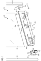
- the FIG. 1 shows a vehicle 10, which may be, for example, a rail vehicle.
- a device component 20 is mounted by means of a fastening device 30.
- the device component 20 in the embodiment according to FIG. 1 two parallel frame sections 21 and 22 and an intermediate separating part 23, which may be, for example, a glass pane.
- the separating part 23 is connected at the edge to the two frame sections 21 and 22.
- the vehicle floor 11 forms a first part of an arrangement in which the first part a second part in the form of the device component 20 is connected by means of the fastening device 30.
- the fastening device 30 comprises an extruded profile part 40 and two angle elements 50 and 51, which are preferably identical in construction and are connected to the extruded profile part 40, in particular screwed.
- fixing elements 60 which are preferably screws.
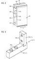
- the profile cross section of the extruded section 40 is closer in the FIG. 2 shown. It can be seen an outer plate 410, which rest on the vehicle floor 11 according to FIG. 1 serves. Parallel to the outer plate 410, a second plate 420 is arranged, which is connected to the outer plate 410 by two side walls 430 and 440. The two side walls 430 and 440 are preferably arranged parallel to one another. The two side walls 430 and 440, the outer plate 410 and the second plate 420 form a cross-sectionally closed lower extruded section 450 of the extruded section 40.
- the extruded section 450 extends in the extrusion direction S tubular with a polygonal and approximately rectangular cross-section.
- the lower extruded profile section 450 serves to receive the two angle elements 50 and 51 according to FIG. 1 ,
- FIG. 2 FIG. 4 also shows a third plate 460 which, together with the second plate 420 and the two side walls 430 and 440, forms a cross-sectionally closed, upper extruded profile section 470 of the extruded profile part 40.
- the upper extruded profile section 470 also extends in a tubular manner along the extrusion direction S of the extruded profile part 40.
- the two side walls 430 and 440 extend beyond the upper extruded section 470 and, together with the third plate 460, form a section 480, viewed in cross-section, which is U-shaped.
- the U-shaped portion 480 forms a receiving groove 481, into which a support portion 20a of the device component 20 according to FIG. 1 can be inserted for fixing on the extruded section 40.
- the support portion 20 a of the device component 20 is formed by a lower edge of the separator 23.
- components shown may be as follows:
- the angle element 50 is connected to the extruded section 40. This is done by a first portion 50a is inserted from the end face 40a in the lower extruded section 450 and then connected to the second plate 420, in particular screwed. The screwing of the first portion 50a takes place by means of the fixing elements 60.
- the fixing elements 60 are preferably screwed into threads which have been previously cut into the second plate 420.
- the angle member 51 Before or after the angle member 51 is inserted in a corresponding manner on the end face 40b in the lower extruded section 450, and it is the first portion 51a of the angle member 51 connected to the second plate 420, in particular screwed.
- the second portion 50b of the angle member 50 is connected to the frame portion 21, in particular screwed.
- the frame section 21 extends on the end face 40a of the extruded profile part 40 and past the angle part 50 in the direction of the vehicle floor 11.
- fixing elements 61 which may be, for example, screws.
- the fixing elements 61 are preferably screwed into threads which are present in the frame section 21.
- the separating part 23 of the device component 20 is inserted into the receiving groove 481 of the extruded profile part 40.
- the extruded section 40 Before or after the extruded section 40 is connected to the vehicle floor 11 of the vehicle 10, preferably screwed.
- holes 411 are provided in the outer plate 410, which are spaced along the extrusion direction S of the extruded section 40.
- recesses 441 are provided in the side wall 440, as shown in FIGS FIG. 1 is shown.
- corresponding recesses may also be provided in the side wall 430, but this is not absolutely necessary.
- the recess 441 which is provided in the region of the end face 40a of the extruded section 40, not only facilitates attachment of the extruded section 40 on the vehicle floor 11, but also connecting the first section 50a of the angled section 50 to the overlying second plate 420 of the Extruded section 40.
- this recess 441 also simplifies the Access to the fixing elements 61, which serve to connect the second portion 50 b of the angle part 50 with the frame portion 21.
- the recess 441 provided in the region of the end face 40b of the extruded profile part 40 correspondingly simplifies access to the holes 411 in this section of the extruded profile part 40 and furthermore connects the first section 51a of the angle element 51 to the second plate 420 of the extruded profile part 40 above and connecting the second portion 51b of the angle member 51 to the frame portion 22 of the device component 20.
- the device component 20 is connected to the vehicle floor 11 of the vehicle 10 by means of a plurality of assembly steps, the order of which is arbitrary.
- the extruded section 40 can be mounted on the vehicle floor 11 before the device component 20 or the angle elements 50 and 51 are mounted.
- the order is arbitrary, since the described embodiment of the extruded profile part 40 and the described embodiment of the angle elements 50 and 51 can always be used to access all fixing elements 60 and 61 independently of previous assembly steps.
- FIG. 3 shows the configuration of the two angle elements 50 and 51 again in another illustration. It can be seen the first portion 50a and 51a, which serves for connection to the second plate 420 of the extruded section 40 and this is equipped with holes 500a, through which the fixing elements 60 according to FIG. 1 can be passed.
- the fixing elements 60 are preferably in thread screwed, which are provided in the second plate 420 of the extruded section 40.
- the second section 50b or 51b which serves for connecting the extruded profile part 40 with the two frame sections 21 and 22 of the device component 20 and for this purpose is provided with holes 500b through which the fixing elements 61 according to FIG. 1 can be passed.
Landscapes
- Engineering & Computer Science (AREA)
- General Engineering & Computer Science (AREA)
- Mechanical Engineering (AREA)
- Architecture (AREA)
- Physics & Mathematics (AREA)
- Electromagnetism (AREA)
- Civil Engineering (AREA)
- Structural Engineering (AREA)
- Body Structure For Vehicles (AREA)
- Furniture Connections (AREA)
Applications Claiming Priority (1)
| Application Number | Priority Date | Filing Date | Title |
|---|---|---|---|
| DE102015204144.1A DE102015204144A1 (de) | 2015-03-09 | 2015-03-09 | Anordnung mit einer Befestigungseinrichtung |
Publications (2)
| Publication Number | Publication Date |
|---|---|
| EP3067496A1 true EP3067496A1 (fr) | 2016-09-14 |
| EP3067496B1 EP3067496B1 (fr) | 2020-08-26 |
Family
ID=55453034
Family Applications (1)
| Application Number | Title | Priority Date | Filing Date |
|---|---|---|---|
| EP16157072.6A Active EP3067496B1 (fr) | 2015-03-09 | 2016-02-24 | Systeme dote d'un dispositif de fixation |
Country Status (3)
| Country | Link |
|---|---|
| EP (1) | EP3067496B1 (fr) |
| DE (1) | DE102015204144A1 (fr) |
| ES (1) | ES2833026T3 (fr) |
Citations (2)
| Publication number | Priority date | Publication date | Assignee | Title |
|---|---|---|---|---|
| FR2667490A1 (fr) * | 1990-10-04 | 1992-04-10 | Cherel Alain | Elements de structure pour l'amenagement d'espaces de rangement. |
| EP1916372A2 (fr) * | 2006-10-23 | 2008-04-30 | Hawa Ag | Dispositif pour le maintien de panneaux et élément de séparation |
Family Cites Families (10)
| Publication number | Priority date | Publication date | Assignee | Title |
|---|---|---|---|---|
| CH682252A5 (en) * | 1990-10-30 | 1993-08-13 | Alusuisse Lonza Services Ag | Corner connection of two profiles with C=profile attachments - has attachments with two arms at free ends of which are counterpoised fillets with one profile having longitudinal grooves on its outer and inner sides |
| DE9102254U1 (de) * | 1991-02-26 | 1991-05-16 | Wallau, Helmut, 5464 Buchholz | Winkelelement |
| DE9200645U1 (de) * | 1992-01-21 | 1992-04-16 | Festo KG, 7300 Esslingen | Profilteil |
| ES2126864T3 (es) * | 1994-07-25 | 1999-04-01 | Alusuisse Lonza Services Ag | Elemento de union. |
| US6722811B2 (en) * | 2002-02-20 | 2004-04-20 | Blanking Systems, Inc. | Lower frame assembly for blanking tool |
| DE10210812B4 (de) * | 2002-03-12 | 2005-06-16 | Dorma Gmbh + Co. Kg | Trag- und Führungseinrichtung zum Halten von ortsveränderlichen, hängend gelagerten Tür- oder Wandelementen |
| US20060182492A1 (en) * | 2005-02-01 | 2006-08-17 | Adam's Specialty Products, Llc | Draw-wedge fasteners |
| JP2007263184A (ja) * | 2006-03-28 | 2007-10-11 | Showa Aircraft Ind Co Ltd | ジョイント用のインサート材 |
| DE202009007517U1 (de) * | 2009-05-20 | 2009-12-10 | Trienergy Gmbh | Ständer für rechteckige Solarmodule |
| DE202012010973U1 (de) * | 2012-06-12 | 2012-11-27 | Altec Solartechnik Ag | Profilschiene für Unterkonstruktionen sowie Befestigungselement hierfür |
-
2015
- 2015-03-09 DE DE102015204144.1A patent/DE102015204144A1/de not_active Ceased
-
2016
- 2016-02-24 ES ES16157072T patent/ES2833026T3/es active Active
- 2016-02-24 EP EP16157072.6A patent/EP3067496B1/fr active Active
Patent Citations (2)
| Publication number | Priority date | Publication date | Assignee | Title |
|---|---|---|---|---|
| FR2667490A1 (fr) * | 1990-10-04 | 1992-04-10 | Cherel Alain | Elements de structure pour l'amenagement d'espaces de rangement. |
| EP1916372A2 (fr) * | 2006-10-23 | 2008-04-30 | Hawa Ag | Dispositif pour le maintien de panneaux et élément de séparation |
Also Published As
| Publication number | Publication date |
|---|---|
| ES2833026T3 (es) | 2021-06-14 |
| EP3067496B1 (fr) | 2020-08-26 |
| DE102015204144A1 (de) | 2016-09-15 |
Similar Documents
| Publication | Publication Date | Title |
|---|---|---|
| EP3001931B1 (fr) | Dispositif de recouvrement d'obturateur | |
| DE102014000839B4 (de) | Messe-Fertigbausystem mit Fertig-Rahmenmodulen | |
| DE102012206288A1 (de) | Verkleidung einer Innenseite einer Seitenwand eines Schienenfahrzeugs | |
| EP2508407A1 (fr) | Structure, en particulier pour les installations électriques dans un véhicule sur rail, et procédé de fabrication de cette structure | |
| DE102016115404A1 (de) | System zur Festlegung wenigstens eines Wandverkleidungsteils | |
| DE102011112074A1 (de) | Möbeleinheit | |
| EP2868544B1 (fr) | Dispositif de fixation pour un profilé de transition dans un véhicule sur rail, composant pour un dispositif de fixation et procédé de fixation d'un profilé de transition | |
| DE102012110247A1 (de) | Schaltschrank mit verbesserter Möglichkeit zur Aneinanderreihung | |
| DE102016115410A1 (de) | Sytem zur Festlegung wenigstens eines Wandverkleidungsteils | |
| DE202015005659U1 (de) | Profilsystem zur Bildung eines Untertragrahmens für die Aufnahme von Bodendielen und Profilschiene | |
| DE102014202783B4 (de) | Flugzeugkabinenanordnung | |
| DE202018105796U1 (de) | Trockenbau-Tragrahmen für eine Schiebetür | |
| EP3140174B1 (fr) | Véhicule, en particulier véhicule ferroviaire, équipé d'un rail de montage | |
| EP1798186B1 (fr) | Cabine d'ascenseur et méthode de montage de panneaux d'une parroi de cabine | |
| EP3342305A1 (fr) | Support de poteau et procédé de montage d'un support de poteau | |
| EP3183998B1 (fr) | Tiroir pour un meuble sous évier | |
| EP3067496B1 (fr) | Systeme dote d'un dispositif de fixation | |
| DE102010018368A1 (de) | Trennwandsystem für den Innenausbau | |
| EP4114150A1 (fr) | Ensemble d'extension | |
| EP2084990A1 (fr) | Support de fond de rayonnage et système de réglage | |
| EP3130716B1 (fr) | Panneau de mur et systeme de panneaux de mur pour la construction de stand d'exposition | |
| EP4424210B1 (fr) | Tiroir d'étagère | |
| DE29713191U1 (de) | Schiebeflügel mit einem aus Metallprofilen hergestellten Rahmen | |
| EP3685705A1 (fr) | Profilé de construction des dispositifs de fonctionnement et dispositif de fonctionnement | |
| DE19933252B4 (de) | Trennwandsystem |
Legal Events
| Date | Code | Title | Description |
|---|---|---|---|
| PUAI | Public reference made under article 153(3) epc to a published international application that has entered the european phase |
Free format text: ORIGINAL CODE: 0009012 |
|
| AK | Designated contracting states |
Kind code of ref document: A1 Designated state(s): AL AT BE BG CH CY CZ DE DK EE ES FI FR GB GR HR HU IE IS IT LI LT LU LV MC MK MT NL NO PL PT RO RS SE SI SK SM TR |
|
| AX | Request for extension of the european patent |
Extension state: BA ME |
|
| STAA | Information on the status of an ep patent application or granted ep patent |
Free format text: STATUS: REQUEST FOR EXAMINATION WAS MADE |
|
| 17P | Request for examination filed |
Effective date: 20170313 |
|
| RBV | Designated contracting states (corrected) |
Designated state(s): AL AT BE BG CH CY CZ DE DK EE ES FI FR GB GR HR HU IE IS IT LI LT LU LV MC MK MT NL NO PL PT RO RS SE SI SK SM TR |
|
| RAP1 | Party data changed (applicant data changed or rights of an application transferred) |
Owner name: SIEMENS AKTIENGESELLSCHAFT |
|
| RAP1 | Party data changed (applicant data changed or rights of an application transferred) |
Owner name: SIEMENS MOBILITY GMBH |
|
| STAA | Information on the status of an ep patent application or granted ep patent |
Free format text: STATUS: EXAMINATION IS IN PROGRESS |
|
| 17Q | First examination report despatched |
Effective date: 20190717 |
|
| GRAP | Despatch of communication of intention to grant a patent |
Free format text: ORIGINAL CODE: EPIDOSNIGR1 |
|
| STAA | Information on the status of an ep patent application or granted ep patent |
Free format text: STATUS: GRANT OF PATENT IS INTENDED |
|
| INTG | Intention to grant announced |
Effective date: 20200430 |
|
| GRAS | Grant fee paid |
Free format text: ORIGINAL CODE: EPIDOSNIGR3 |
|
| GRAA | (expected) grant |
Free format text: ORIGINAL CODE: 0009210 |
|
| STAA | Information on the status of an ep patent application or granted ep patent |
Free format text: STATUS: THE PATENT HAS BEEN GRANTED |
|
| AK | Designated contracting states |
Kind code of ref document: B1 Designated state(s): AL AT BE BG CH CY CZ DE DK EE ES FI FR GB GR HR HU IE IS IT LI LT LU LV MC MK MT NL NO PL PT RO RS SE SI SK SM TR |
|
| REG | Reference to a national code |
Ref country code: GB Ref legal event code: FG4D Free format text: NOT ENGLISH |
|
| REG | Reference to a national code |
Ref country code: CH Ref legal event code: EP |
|
| REG | Reference to a national code |
Ref country code: AT Ref legal event code: REF Ref document number: 1306523 Country of ref document: AT Kind code of ref document: T Effective date: 20200915 |
|
| REG | Reference to a national code |
Ref country code: IE Ref legal event code: FG4D Free format text: LANGUAGE OF EP DOCUMENT: GERMAN |
|
| REG | Reference to a national code |
Ref country code: DE Ref legal event code: R096 Ref document number: 502016010923 Country of ref document: DE |
|
| REG | Reference to a national code |
Ref country code: CH Ref legal event code: NV Representative=s name: SIEMENS SCHWEIZ AG, CH |
|
| REG | Reference to a national code |
Ref country code: LT Ref legal event code: MG4D |
|
| PG25 | Lapsed in a contracting state [announced via postgrant information from national office to epo] |
Ref country code: FI Free format text: LAPSE BECAUSE OF FAILURE TO SUBMIT A TRANSLATION OF THE DESCRIPTION OR TO PAY THE FEE WITHIN THE PRESCRIBED TIME-LIMIT Effective date: 20200826 Ref country code: GR Free format text: LAPSE BECAUSE OF FAILURE TO SUBMIT A TRANSLATION OF THE DESCRIPTION OR TO PAY THE FEE WITHIN THE PRESCRIBED TIME-LIMIT Effective date: 20201127 Ref country code: NO Free format text: LAPSE BECAUSE OF FAILURE TO SUBMIT A TRANSLATION OF THE DESCRIPTION OR TO PAY THE FEE WITHIN THE PRESCRIBED TIME-LIMIT Effective date: 20201126 Ref country code: SE Free format text: LAPSE BECAUSE OF FAILURE TO SUBMIT A TRANSLATION OF THE DESCRIPTION OR TO PAY THE FEE WITHIN THE PRESCRIBED TIME-LIMIT Effective date: 20200826 Ref country code: HR Free format text: LAPSE BECAUSE OF FAILURE TO SUBMIT A TRANSLATION OF THE DESCRIPTION OR TO PAY THE FEE WITHIN THE PRESCRIBED TIME-LIMIT Effective date: 20200826 Ref country code: LT Free format text: LAPSE BECAUSE OF FAILURE TO SUBMIT A TRANSLATION OF THE DESCRIPTION OR TO PAY THE FEE WITHIN THE PRESCRIBED TIME-LIMIT Effective date: 20200826 Ref country code: BG Free format text: LAPSE BECAUSE OF FAILURE TO SUBMIT A TRANSLATION OF THE DESCRIPTION OR TO PAY THE FEE WITHIN THE PRESCRIBED TIME-LIMIT Effective date: 20201126 Ref country code: PT Free format text: LAPSE BECAUSE OF FAILURE TO SUBMIT A TRANSLATION OF THE DESCRIPTION OR TO PAY THE FEE WITHIN THE PRESCRIBED TIME-LIMIT Effective date: 20201228 |
|
| REG | Reference to a national code |
Ref country code: NL Ref legal event code: MP Effective date: 20200826 |
|
| PG25 | Lapsed in a contracting state [announced via postgrant information from national office to epo] |
Ref country code: IS Free format text: LAPSE BECAUSE OF FAILURE TO SUBMIT A TRANSLATION OF THE DESCRIPTION OR TO PAY THE FEE WITHIN THE PRESCRIBED TIME-LIMIT Effective date: 20201226 Ref country code: LV Free format text: LAPSE BECAUSE OF FAILURE TO SUBMIT A TRANSLATION OF THE DESCRIPTION OR TO PAY THE FEE WITHIN THE PRESCRIBED TIME-LIMIT Effective date: 20200826 Ref country code: NL Free format text: LAPSE BECAUSE OF FAILURE TO SUBMIT A TRANSLATION OF THE DESCRIPTION OR TO PAY THE FEE WITHIN THE PRESCRIBED TIME-LIMIT Effective date: 20200826 Ref country code: PL Free format text: LAPSE BECAUSE OF FAILURE TO SUBMIT A TRANSLATION OF THE DESCRIPTION OR TO PAY THE FEE WITHIN THE PRESCRIBED TIME-LIMIT Effective date: 20200826 Ref country code: RS Free format text: LAPSE BECAUSE OF FAILURE TO SUBMIT A TRANSLATION OF THE DESCRIPTION OR TO PAY THE FEE WITHIN THE PRESCRIBED TIME-LIMIT Effective date: 20200826 |
|
| PG25 | Lapsed in a contracting state [announced via postgrant information from national office to epo] |
Ref country code: EE Free format text: LAPSE BECAUSE OF FAILURE TO SUBMIT A TRANSLATION OF THE DESCRIPTION OR TO PAY THE FEE WITHIN THE PRESCRIBED TIME-LIMIT Effective date: 20200826 Ref country code: RO Free format text: LAPSE BECAUSE OF FAILURE TO SUBMIT A TRANSLATION OF THE DESCRIPTION OR TO PAY THE FEE WITHIN THE PRESCRIBED TIME-LIMIT Effective date: 20200826 Ref country code: SM Free format text: LAPSE BECAUSE OF FAILURE TO SUBMIT A TRANSLATION OF THE DESCRIPTION OR TO PAY THE FEE WITHIN THE PRESCRIBED TIME-LIMIT Effective date: 20200826 Ref country code: DK Free format text: LAPSE BECAUSE OF FAILURE TO SUBMIT A TRANSLATION OF THE DESCRIPTION OR TO PAY THE FEE WITHIN THE PRESCRIBED TIME-LIMIT Effective date: 20200826 Ref country code: CZ Free format text: LAPSE BECAUSE OF FAILURE TO SUBMIT A TRANSLATION OF THE DESCRIPTION OR TO PAY THE FEE WITHIN THE PRESCRIBED TIME-LIMIT Effective date: 20200826 |
|
| REG | Reference to a national code |
Ref country code: DE Ref legal event code: R097 Ref document number: 502016010923 Country of ref document: DE |
|
| PG25 | Lapsed in a contracting state [announced via postgrant information from national office to epo] |
Ref country code: AL Free format text: LAPSE BECAUSE OF FAILURE TO SUBMIT A TRANSLATION OF THE DESCRIPTION OR TO PAY THE FEE WITHIN THE PRESCRIBED TIME-LIMIT Effective date: 20200826 |
|
| REG | Reference to a national code |
Ref country code: ES Ref legal event code: FG2A Ref document number: 2833026 Country of ref document: ES Kind code of ref document: T3 Effective date: 20210614 |
|
| PG25 | Lapsed in a contracting state [announced via postgrant information from national office to epo] |
Ref country code: SK Free format text: LAPSE BECAUSE OF FAILURE TO SUBMIT A TRANSLATION OF THE DESCRIPTION OR TO PAY THE FEE WITHIN THE PRESCRIBED TIME-LIMIT Effective date: 20200826 |
|
| PLBE | No opposition filed within time limit |
Free format text: ORIGINAL CODE: 0009261 |
|
| STAA | Information on the status of an ep patent application or granted ep patent |
Free format text: STATUS: NO OPPOSITION FILED WITHIN TIME LIMIT |
|
| 26N | No opposition filed |
Effective date: 20210527 |
|
| PG25 | Lapsed in a contracting state [announced via postgrant information from national office to epo] |
Ref country code: SI Free format text: LAPSE BECAUSE OF FAILURE TO SUBMIT A TRANSLATION OF THE DESCRIPTION OR TO PAY THE FEE WITHIN THE PRESCRIBED TIME-LIMIT Effective date: 20200826 |
|
| PG25 | Lapsed in a contracting state [announced via postgrant information from national office to epo] |
Ref country code: MC Free format text: LAPSE BECAUSE OF FAILURE TO SUBMIT A TRANSLATION OF THE DESCRIPTION OR TO PAY THE FEE WITHIN THE PRESCRIBED TIME-LIMIT Effective date: 20200826 |
|
| PG25 | Lapsed in a contracting state [announced via postgrant information from national office to epo] |
Ref country code: LU Free format text: LAPSE BECAUSE OF NON-PAYMENT OF DUE FEES Effective date: 20210224 |
|
| PG25 | Lapsed in a contracting state [announced via postgrant information from national office to epo] |
Ref country code: IE Free format text: LAPSE BECAUSE OF NON-PAYMENT OF DUE FEES Effective date: 20210224 |
|
| PG25 | Lapsed in a contracting state [announced via postgrant information from national office to epo] |
Ref country code: HU Free format text: LAPSE BECAUSE OF FAILURE TO SUBMIT A TRANSLATION OF THE DESCRIPTION OR TO PAY THE FEE WITHIN THE PRESCRIBED TIME-LIMIT; INVALID AB INITIO Effective date: 20160224 |
|
| PG25 | Lapsed in a contracting state [announced via postgrant information from national office to epo] |
Ref country code: CY Free format text: LAPSE BECAUSE OF FAILURE TO SUBMIT A TRANSLATION OF THE DESCRIPTION OR TO PAY THE FEE WITHIN THE PRESCRIBED TIME-LIMIT Effective date: 20200826 |
|
| PG25 | Lapsed in a contracting state [announced via postgrant information from national office to epo] |
Ref country code: MK Free format text: LAPSE BECAUSE OF FAILURE TO SUBMIT A TRANSLATION OF THE DESCRIPTION OR TO PAY THE FEE WITHIN THE PRESCRIBED TIME-LIMIT Effective date: 20200826 |
|
| PG25 | Lapsed in a contracting state [announced via postgrant information from national office to epo] |
Ref country code: MT Free format text: LAPSE BECAUSE OF FAILURE TO SUBMIT A TRANSLATION OF THE DESCRIPTION OR TO PAY THE FEE WITHIN THE PRESCRIBED TIME-LIMIT Effective date: 20200826 |
|
| PGFP | Annual fee paid to national office [announced via postgrant information from national office to epo] |
Ref country code: AT Payment date: 20250110 Year of fee payment: 10 Ref country code: BE Payment date: 20250218 Year of fee payment: 10 |
|
| PGFP | Annual fee paid to national office [announced via postgrant information from national office to epo] |
Ref country code: TR Payment date: 20250217 Year of fee payment: 10 |
|
| REG | Reference to a national code |
Ref country code: DE Ref legal event code: R081 Ref document number: 502016010923 Country of ref document: DE Owner name: SIEMENS MOBILITY GMBH, DE Free format text: FORMER OWNER: SIEMENS AKTIENGESELLSCHAFT, 80333 MUENCHEN, DE |
|
| PGFP | Annual fee paid to national office [announced via postgrant information from national office to epo] |
Ref country code: GB Payment date: 20260310 Year of fee payment: 11 |
|
| PGFP | Annual fee paid to national office [announced via postgrant information from national office to epo] |
Ref country code: IT Payment date: 20260225 Year of fee payment: 11 |
|
| PGFP | Annual fee paid to national office [announced via postgrant information from national office to epo] |
Ref country code: FR Payment date: 20260213 Year of fee payment: 11 |
|
| REG | Reference to a national code |
Ref country code: CH Ref legal event code: U11 Free format text: ST27 STATUS EVENT CODE: U-0-0-U10-U11 (AS PROVIDED BY THE NATIONAL OFFICE) Effective date: 20260511 |
|
| PGFP | Annual fee paid to national office [announced via postgrant information from national office to epo] |
Ref country code: ES Payment date: 20260522 Year of fee payment: 11 |
|
| PGFP | Annual fee paid to national office [announced via postgrant information from national office to epo] |
Ref country code: DE Payment date: 20260420 Year of fee payment: 11 |
|
| PGFP | Annual fee paid to national office [announced via postgrant information from national office to epo] |
Ref country code: CH Payment date: 20260511 Year of fee payment: 11 |