EP3067628A1 - Vanne hydraulique - Google Patents
Vanne hydraulique Download PDFInfo
- Publication number
- EP3067628A1 EP3067628A1 EP15158772.2A EP15158772A EP3067628A1 EP 3067628 A1 EP3067628 A1 EP 3067628A1 EP 15158772 A EP15158772 A EP 15158772A EP 3067628 A1 EP3067628 A1 EP 3067628A1
- Authority
- EP
- European Patent Office
- Prior art keywords
- hydraulic
- module
- load
- circuit board
- load module
- Prior art date
- Legal status (The legal status is an assumption and is not a legal conclusion. Google has not performed a legal analysis and makes no representation as to the accuracy of the status listed.)
- Granted
Links
- 230000008878 coupling Effects 0.000 claims abstract description 72
- 238000010168 coupling process Methods 0.000 claims abstract description 72
- 238000005859 coupling reaction Methods 0.000 claims abstract description 72
- 230000001105 regulatory effect Effects 0.000 claims abstract description 45
- 238000010438 heat treatment Methods 0.000 claims abstract description 17
- 238000001816 cooling Methods 0.000 claims abstract description 16
- 238000004891 communication Methods 0.000 claims description 5
- 230000001276 controlling effect Effects 0.000 claims description 2
- 230000000295 complement effect Effects 0.000 description 4
- 239000007788 liquid Substances 0.000 description 4
- XLYOFNOQVPJJNP-UHFFFAOYSA-N water Substances O XLYOFNOQVPJJNP-UHFFFAOYSA-N 0.000 description 3
- 238000003780 insertion Methods 0.000 description 2
- 230000037431 insertion Effects 0.000 description 2
- WYTGDNHDOZPMIW-RCBQFDQVSA-N alstonine Natural products C1=CC2=C3C=CC=CC3=NC2=C2N1C[C@H]1[C@H](C)OC=C(C(=O)OC)[C@H]1C2 WYTGDNHDOZPMIW-RCBQFDQVSA-N 0.000 description 1
- 230000009286 beneficial effect Effects 0.000 description 1
- 239000004020 conductor Substances 0.000 description 1
- 238000010276 construction Methods 0.000 description 1
- 230000005489 elastic deformation Effects 0.000 description 1
- 238000009429 electrical wiring Methods 0.000 description 1
- 238000002347 injection Methods 0.000 description 1
- 239000007924 injection Substances 0.000 description 1
- 238000009434 installation Methods 0.000 description 1
- 238000004519 manufacturing process Methods 0.000 description 1
- 239000000463 material Substances 0.000 description 1
- 150000003071 polychlorinated biphenyls Chemical group 0.000 description 1
- 238000007789 sealing Methods 0.000 description 1
- 238000007493 shaping process Methods 0.000 description 1
Images



Classifications
-
- F—MECHANICAL ENGINEERING; LIGHTING; HEATING; WEAPONS; BLASTING
- F24—HEATING; RANGES; VENTILATING
- F24D—DOMESTIC- OR SPACE-HEATING SYSTEMS, e.g. CENTRAL HEATING SYSTEMS; DOMESTIC HOT-WATER SUPPLY SYSTEMS; ELEMENTS OR COMPONENTS THEREFOR
- F24D3/00—Hot-water central heating systems
- F24D3/12—Tube and panel arrangements for ceiling, wall, or underfloor heating
- F24D3/122—Details
-
- F—MECHANICAL ENGINEERING; LIGHTING; HEATING; WEAPONS; BLASTING
- F16—ENGINEERING ELEMENTS AND UNITS; GENERAL MEASURES FOR PRODUCING AND MAINTAINING EFFECTIVE FUNCTIONING OF MACHINES OR INSTALLATIONS; THERMAL INSULATION IN GENERAL
- F16K—VALVES; TAPS; COCKS; ACTUATING-FLOATS; DEVICES FOR VENTING OR AERATING
- F16K11/00—Multiple-way valves, e.g. mixing valves; Pipe fittings incorporating such valves
- F16K11/10—Multiple-way valves, e.g. mixing valves; Pipe fittings incorporating such valves with two or more closure members not moving as a unit
- F16K11/20—Multiple-way valves, e.g. mixing valves; Pipe fittings incorporating such valves with two or more closure members not moving as a unit operated by separate actuating members
- F16K11/22—Multiple-way valves, e.g. mixing valves; Pipe fittings incorporating such valves with two or more closure members not moving as a unit operated by separate actuating members with an actuating member for each valve, e.g. interconnected to form multiple-way valves
-
- F—MECHANICAL ENGINEERING; LIGHTING; HEATING; WEAPONS; BLASTING
- F16—ENGINEERING ELEMENTS AND UNITS; GENERAL MEASURES FOR PRODUCING AND MAINTAINING EFFECTIVE FUNCTIONING OF MACHINES OR INSTALLATIONS; THERMAL INSULATION IN GENERAL
- F16K—VALVES; TAPS; COCKS; ACTUATING-FLOATS; DEVICES FOR VENTING OR AERATING
- F16K19/00—Arrangements of valves and flow lines specially adapted for mixing fluids
- F16K19/003—Specially adapted for boilers
-
- F—MECHANICAL ENGINEERING; LIGHTING; HEATING; WEAPONS; BLASTING
- F16—ENGINEERING ELEMENTS AND UNITS; GENERAL MEASURES FOR PRODUCING AND MAINTAINING EFFECTIVE FUNCTIONING OF MACHINES OR INSTALLATIONS; THERMAL INSULATION IN GENERAL
- F16K—VALVES; TAPS; COCKS; ACTUATING-FLOATS; DEVICES FOR VENTING OR AERATING
- F16K27/00—Construction of housing; Use of materials therefor
- F16K27/003—Housing formed from a plurality of the same valve elements
-
- F—MECHANICAL ENGINEERING; LIGHTING; HEATING; WEAPONS; BLASTING
- F16—ENGINEERING ELEMENTS AND UNITS; GENERAL MEASURES FOR PRODUCING AND MAINTAINING EFFECTIVE FUNCTIONING OF MACHINES OR INSTALLATIONS; THERMAL INSULATION IN GENERAL
- F16K—VALVES; TAPS; COCKS; ACTUATING-FLOATS; DEVICES FOR VENTING OR AERATING
- F16K31/00—Actuating devices; Operating means; Releasing devices
- F16K31/02—Actuating devices; Operating means; Releasing devices electric; magnetic
-
- F—MECHANICAL ENGINEERING; LIGHTING; HEATING; WEAPONS; BLASTING
- F24—HEATING; RANGES; VENTILATING
- F24D—DOMESTIC- OR SPACE-HEATING SYSTEMS, e.g. CENTRAL HEATING SYSTEMS; DOMESTIC HOT-WATER SUPPLY SYSTEMS; ELEMENTS OR COMPONENTS THEREFOR
- F24D3/00—Hot-water central heating systems
- F24D3/10—Feed-line arrangements, e.g. providing for heat-accumulator tanks, expansion tanks ; Hydraulic components of a central heating system
- F24D3/1058—Feed-line arrangements, e.g. providing for heat-accumulator tanks, expansion tanks ; Hydraulic components of a central heating system disposition of pipes and pipe connections
- F24D3/1066—Distributors for heating liquids
- F24D3/1075—Built up from modules
-
- F—MECHANICAL ENGINEERING; LIGHTING; HEATING; WEAPONS; BLASTING
- F24—HEATING; RANGES; VENTILATING
- F24D—DOMESTIC- OR SPACE-HEATING SYSTEMS, e.g. CENTRAL HEATING SYSTEMS; DOMESTIC HOT-WATER SUPPLY SYSTEMS; ELEMENTS OR COMPONENTS THEREFOR
- F24D3/00—Hot-water central heating systems
- F24D3/12—Tube and panel arrangements for ceiling, wall, or underfloor heating
- F24D3/122—Details
- F24D3/125—Hydraulic pipe connections
-
- F—MECHANICAL ENGINEERING; LIGHTING; HEATING; WEAPONS; BLASTING
- F24—HEATING; RANGES; VENTILATING
- F24D—DOMESTIC- OR SPACE-HEATING SYSTEMS, e.g. CENTRAL HEATING SYSTEMS; DOMESTIC HOT-WATER SUPPLY SYSTEMS; ELEMENTS OR COMPONENTS THEREFOR
- F24D3/00—Hot-water central heating systems
- F24D3/12—Tube and panel arrangements for ceiling, wall, or underfloor heating
- F24D3/14—Tube and panel arrangements for ceiling, wall, or underfloor heating incorporated in a ceiling, wall or floor
-
- F—MECHANICAL ENGINEERING; LIGHTING; HEATING; WEAPONS; BLASTING
- F24—HEATING; RANGES; VENTILATING
- F24F—AIR-CONDITIONING; AIR-HUMIDIFICATION; VENTILATION; USE OF AIR CURRENTS FOR SCREENING
- F24F5/00—Air-conditioning systems or apparatus not covered by F24F1/00 or F24F3/00, e.g. using solar heat or combined with household units such as an oven or water heater
- F24F5/0089—Systems using radiation from walls or panels
-
- F—MECHANICAL ENGINEERING; LIGHTING; HEATING; WEAPONS; BLASTING
- F01—MACHINES OR ENGINES IN GENERAL; ENGINE PLANTS IN GENERAL; STEAM ENGINES
- F01L—CYCLICALLY OPERATING VALVES FOR MACHINES OR ENGINES
- F01L3/00—Lift-valve, i.e. cut-off apparatus with closure members having at least a component of their opening and closing motion perpendicular to the closing faces; Parts or accessories thereof
- F01L3/02—Selecting particular materials for valve-members or valve-seats; Valve-members or valve-seats composed of two or more materials
-
- Y—GENERAL TAGGING OF NEW TECHNOLOGICAL DEVELOPMENTS; GENERAL TAGGING OF CROSS-SECTIONAL TECHNOLOGIES SPANNING OVER SEVERAL SECTIONS OF THE IPC; TECHNICAL SUBJECTS COVERED BY FORMER USPC CROSS-REFERENCE ART COLLECTIONS [XRACs] AND DIGESTS
- Y02—TECHNOLOGIES OR APPLICATIONS FOR MITIGATION OR ADAPTATION AGAINST CLIMATE CHANGE
- Y02B—CLIMATE CHANGE MITIGATION TECHNOLOGIES RELATED TO BUILDINGS, e.g. HOUSING, HOUSE APPLIANCES OR RELATED END-USER APPLICATIONS
- Y02B30/00—Energy efficient heating, ventilation or air conditioning [HVAC]
Definitions
- the invention relates to a hydraulic distributor for a hydraulic heating and / or cooling system.
- Hydraulic distributors are used, for example, in heating systems with several heating circuits, in particular in conjunction with underfloor heating circuits, in order to be able to individually regulate the flow of a liquid heat carrier through the individual heating circuits.
- differently sized distributors are required.
- a separate regulating device for example a valve driven by an electric motor, is required.
- a separate regulating device for example a valve driven by an electric motor.
- the hydraulic distributor according to the invention is designed for use in a hydraulic heating and / or cooling system, i. it is a hydraulic heating and / or cooling distributor.
- a liquid heat carrier in particular water
- Such a hydraulic system may be designed as a pure heating system in which, for example, rooms are heated by a central heat source via a hydraulic system.
- the system can be designed as a cooling system in which objects are cooled by a central cooling source via the hydraulic system.
- such a system may be designed as a combined system, for example to heat in winter and to cool in summer.
- the hydraulic distributor according to the invention has a modular structure, so that it can be adapted to different numbers of load circuits, for example heating and / or cooling circuits.
- the hydraulic distributor has a main module and at least one load module.
- the main module is used to connect the entire hydraulic distributor.
- the load module is used to connect at least one load circuit and has for this purpose at least one hydraulic connection for a load circuit and at least one regulating device for regulating the flow through the load circuit connected to the hydraulic connection.
- the regulating device may be, for example, an electromotive or electrothermally actuated valve.
- the load module is designed to be identical to another Load module can be connected.
- load modules can also be designed such that they each allow the connection of a plurality of load circuits and to have a desired number of terminals.
- load modules with connections for 4 load circuits can be provided, in which case by joining two such load modules, a hydraulic distributor for 8 load circuits can be created.
- a regulating device is preferably provided for each connection.
- a hydraulic connection is preferably formed between the main module and the load module connected to the main module and also between the interconnected load modules.
- Such a hydraulic connection can be designed as a flow or as a return for the individual load circuits.
- the main module and the load modules are designed such that they have both a supply and a return.
- the regulating device can be arranged in the flow or in the return of the respective load module. If the main module and the load modules are designed such that they have only one flow path, ie either supply or return, the respective other flow path can be connected, for example, via a separate hydraulic distributor.
- an electrical connection between the load modules in particular for the electrical connection of a drive of the load modules, is provided according to the invention.
- a printed circuit board is arranged in the at least one load module, which extends from a first end to a second end of the load module.
- this extension direction is the same direction in which several load modules can be strung together, that is, the longitudinal direction of the trained from the load modules hydraulic distributor.
- the first and second ends of the load module are facing away from each other or oppositely directed.
- the circuit board is formed so that it has at its first and second end to each other corresponding electrical couplings. These are preferably multipolar.
- the couplings are designed such that the electrical coupling at the second end of the printed circuit board can electrically engage with an electrical coupling at the first end of a further identical load module. That is, the electrical coupling at the first end is complementary to the electrical coupling at the second end, so that when two identical load modules are present, the first end of one load module can be joined to the second end of the other load module, with the complementary ones electrical couplings electrically conductively engage with each other.
- the fact that the electrical couplings are formed directly on a printed circuit board simplifies the structure of the load module, since all required electrical connections can be combined on a printed circuit board and a printed circuit board manufactured in this way can be used as a prefabricated component in a housing of a load module. There are no further cabling required.
- the main module has an electrical coupling which is complementary to the electrical coupling formed at one end of the load module, so that such a load module can be attached to the main module, wherein the electrical couplings of load module and main module electrically conductively engage ,
- the couplings are preferably designed as plug-in couplings.
- one of the two electrical couplings at the first and the second end female contacts and the other electrical coupling corresponding male contacts may engage each other in a known manner when two correspondingly formed load modules are joined together.
- the printed circuit board in its extension direction between the first and the second end is elastically deformable or resilient.
- This has the advantage that tolerances can be compensated and when juxtaposing several load modules, if they are firmly mated, damage to the circuit board can be avoided, since the circuit board can yield elastically in the joining direction. So on the one hand a secure electrical connection to the electrical couplings can be achieved. On the other hand, electrical components can be protected from damage due to excessive force when assembling the electrical couplings.
- the spring action of the printed circuit board preferably results from a corresponding shaping of the printed circuit board.
- the circuit board on a meandering portion which causes the resilient training.
- a meander-shaped section can be formed, for example, by lateral cuts in the printed circuit board, whereby a serpentine or meandering structure is formed between the cuts.
- the printed circuit board with the regulating device or the electric drive of the regulating device is preferably electrically connected by means of a plug connection.
- a plug connection This allows a very simple installation of the load module, since the required electrical connections can be made by connectors.
- such a design is very easy to maintain because the connector can be disconnected again, for example, to be able to replace a regulator or its drive.
- the printed circuit board preferably carries an electronic module control device or electronic components which form such a module control device, wherein the module control device is used for communication with a distributor control device, which is preferably arranged in the main module and is designed to control the regulating device.
- the distributor control device is preferably designed such that it defines the opening degree for the regulating device of the load module.
- the distributor control device is designed so that it can control a plurality of load modules or their regulating devices.
- the distributor control device can cooperate, for example, with room thermostats in rooms to be tempered, and based on the temperature signals of these room thermostats, specify the degree of opening for the individual regulating devices.
- the central control of the individual regulating devices of several load modules has the advantage that the regulating devices can be controlled in an energy-optimized manner, so that, for example, only one drive at a time a regulating device is simultaneously in operation, so that the total current for the drives of the regulating devices can be kept low.
- the module control devices serve to receive the control signals from the distribution control device and to control the associated regulation device of the load module.
- the module control device thus forms a communication interface of the load module to the distributor control device.
- the control signals can be transmitted from the distributor control device to the individual load modules via a bus system to which the module control devices of a plurality of load modules are connected.
- Characterized in that the electronic components of the module control device are arranged on the circuit board, which also has the electrical couplings, a very simple electrical connection is made possible because the essential electronic elements of the load module can be combined and pre-assembled on the circuit board.
- the electrical couplings are connected at the first and second ends of the load module via the printed circuit board such that electrical signals are passed from the electrical coupling at one of the ends to the electrical coupling at the other end.
- the electrical connections are preferably designed such that all load modules are supplied with energy and, moreover, electrical control signals can be passed through the load module to a following load module.
- a data bus can be formed, which can extend over a plurality of lined-up load modules to the module control devices of these load modules, as described above have been described to connect to a distribution controller for data communication.
- the distributor control device is preferably integrated in the main module. There, it may further preferably be integrated in the electronic control device of a circulating pump arranged in the main module. As a result, the structure is further simplified, since so essential electronic components or control devices can be combined.
- At least one sensor is arranged in the at least one load module, which is electrically connected to the circuit board and more preferably is arranged directly on the circuit board.
- this sensor can be a temperature sensor which detects the temperature directly or indirectly at or in one of the hydraulic connections or in one of the flow paths in the load module.
- the load module may further preferably have a module control device, in particular a module control device, as described above, which detects the signals of the at least one sensor and transmits them to a distributor control device, which may be arranged in particular in the main module.
- a distributor control device which may be arranged in particular in the main module.
- an electrical connection in particular a data bus, which is formed in the manner described by the circuit board can be used.
- the signals or measured values of the at least one sensor can then preferably be used by the distributor control device for controlling or regulating the associated regulating device of the load module.
- the at least one load module further preferably has a module housing, in which a receiving space is formed, in which the circuit board is inserted, wherein the receiving space to the has two ends coupling openings through which the electrical couplings on the circuit board extend to the outside or are accessible from the outside.
- a module housing in which a receiving space is formed, in which the circuit board is inserted, wherein the receiving space to the has two ends coupling openings through which the electrical couplings on the circuit board extend to the outside or are accessible from the outside.
- At least one hydraulic flow path is preferably formed in the module housing and the receiving space for the printed circuit board is separated from the hydraulic flow path.
- the printed circuit board is protected in the receiving space, in particular before contact with the medium flowing in the hydraulic flow path, for example water.
- the module housing has a drive receiving space connected to the hydraulic flow path, in which the regulating device or the electrical drive of the regulating device is arranged.
- the regulating device can be used as a prefabricated unit, in particular as a unit of drive and valve element in the drive receiving space.
- the regulating device may have a valve device and a drive, which are connected to one another via a coupling such that the drive is separated from the regulating device can be. This can be beneficial for repair purposes.
- at least one sealing element, in particular an O-ring is provided between the regulating device and the drive receiving space, which seals the hydraulic flow path to the outside.
- the receiving space for the printed circuit board which has been described above, is preferably also separated from the drive receiving space, so that no moisture from the flow path into the receiving space, in which the circuit board is located with the electrical or electronic components even with leakage of the described seal , can penetrate.
- the regulating device or its electrical drive is furthermore preferably electrically connected to the printed circuit board via a connecting element arranged outside the module housing, wherein the receiving space for the printed circuit board preferably has a connection opening through which the connecting element extends to the printed circuit board.
- the drive receiving space preferably also has an opening through which the connecting element can be connected to the regulating device or the electric drive of the regulating device.
- the connection opening of the receiving space and the opening of the drive receiving space are preferably open in each case to the outside and not directly connected to each other.
- the connecting element is preferably designed such that it has an electrical plug connection to the printed circuit board and / or an electrical plug connection to the regulating device, so that a simple assembly is possible.
- Such a connection element inserted from the outside makes it possible to dispense with a direct connection between the receiving space and the drive receiving space, so that in the described manner the printed circuit board is protected from contact with moisture from the flow path in the receiving space.
- the regulating device is preferably an electrically driven valve or an electrically driven pump.
- the electrically driven valve may e.g. a valve driven by an electric motor, in particular a valve driven by an electric stepper motor.
- an electromagnetic valve or an electrothermally driven valve may also be used.
- the valves are preferably designed so that they can be changed in their opening degree, wherein this can be done via a control of the electric drive via the distributor control device.
- a desired opening degree is preferably transmitted from the distributor control device to the module control device, which then controls or regulates the respective drive of the regulating device in such a way that the desired valve opening degree is achieved.
- the speed control is then preferably carried out by the described distributor control device, wherein required speed signals from the distributor control device preferably transmitted to a module control device of the respective load module and the module control device then activates a connected pump at the desired speed or regulates the rotational speed of the differential pressure or flow to a desired setpoint.
- the at least one load module has at least one flow path extending from the first to the second end, which is connected to the at least one hydraulic connection via the regulating device.
- this flow path may be a flow or a return, wherein the hydraulic connection is corresponding to a flow or return connection for a load circuit to be connected.
- the described flow path thus connects two opposite ends of the load module in particular two mutually remote axial ends of the load module with each other so that when juxtaposing a plurality of load modules extending through the plurality of load modules continuous flow path is formed, which establishes a connection to a hydraulic flow path in the main module.
- different load circuits can be hydraulically connected to the main module via one load module each. At least one branch from this continuous flow path to the hydraulic connection is then provided in each case in the load module.
- the load modules are preferably provided for connection of a single load circuit.
- load modules which have connections for several load circuits, wherein in the load module then preferably a plurality of regulating devices are arranged for the plurality of load circuits.
- load modules which serve to connect a plurality of load circuits, can also be designed in the described manner so that they can be joined together to form a hydraulic distributor with a desired number of terminals for load circuits.
- the at least one load module on a first hydraulic flow path and a second hydraulic flow path which each extend from the first to the second end and are each connected to at least one hydraulic connection of the load module for connection of a load circuit.
- the regulating device lies in the connection between one of the flow paths and an associated hydraulic connection of the load module. This can be a flow or a return as described.
- One of the two hydraulic flow paths forms the flow and the other hydraulic flow path forms the return.
- a hydraulic connection forms one Flow connection and the other hydraulic connection a return connection for a load circuit to be connected to the load module.
- the hydraulic flow paths are preferably completely separated from each other in the load module.
- the at least one flow path in the at least one load module terminates at the first end in a first hydraulic clutch and at the second end in a second hydraulic clutch and the first and second hydraulic clutches are formed corresponding to one another such that the second hydraulic clutch on second end of the load module with the first hydraulic clutch at the first end of an identically formed second load module fluidly connected.
- a plurality of load modules can be lined up with each other, wherein the hydraulic couplings engage each other so that a continuous outwardly sealed flow path is formed from one to the next load module.
- the first load module is preferably connected via a hydraulic coupling corresponding to the main module and a flow path formed in the main module.
- all these load modules can be hydraulically connected in series with the main module.
- a first and a second hydraulic flow path are formed in the load modules, they each have at their ends correspondingly formed hydraulic couplings, so that when juxtaposing multiple load modules in each case the first flow paths and the second flow paths are interconnected so that a first flow path extending through all the load modules and a second flow path extending through all the load modules is formed.
- the first load module adjoining the main module is preferably connected to a first flow path and to a second flow path in the main module. So can over the load modules fore- and Return of the individual load circuits are connected to a flow and return in the main module, for example, the first flow path forms the flow and the second flow path forms the return.
- the hydraulic distributor has a main module and a plurality of load modules, which are formed in the manner described above, wherein the load modules are joined together so that in each case a second end of a first load module with the first end of a subsequent second load module is engaged , One of the load modules is connected in a corresponding manner to the main module.
- the connections between the individual load modules and between the load module and the main module are preferably detachable, so that individual of these load modules can optionally be replaced or the main module can optionally be replaced.
- the hydraulic distributor described here by way of example is designed for use in a hydraulic heating and / or cooling system, in which heat is transported via a liquid heat carrier, in particular water.
- heat can be transported from a central heat source to a plurality of consumers or, in the case of a cooling system, can be removed from the plurality of consumers to a central cooling device.
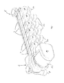
- the hydraulic distributor shown has a modular design and has a main module 2 and, in the example shown, six load modules 4.
- the load modules 4 are all identical. It should be understood that instead of arranging six load modules, more or fewer load modules may be lined up in a corresponding manner.
- a first load module 4 is connected to the main module 2.
- the remaining load modules are attached in series one behind the other to this first load module 4.
- the last load module 4 is closed by a closure module 6 on the side facing away from the main module 2 side.
- the hydraulic distributor serves to distribute a liquid heat carrier to a plurality of load circuits and, in the example shown here, has a supply line and a return line.
- the main module 2 has an input 8 for the flow and an output 10 for the Rewind up.
- the main module 2 also has a circulation pump unit 12, whose impeller is located in the adjacent to the input 8 first flow path, which forms the flow.
- the circulating pump unit 12 has an electronics housing 14, in which a distributor control device is arranged, which controls the speed of the circulating pump unit 12 as well as the individual load modules 4 on the one hand.
- the main module 2 receive a temperature signal from at least one temperature sensor, wherein the control of the load modules and possibly the Ummélzpumpenaggregates based on this temperature signal.
- a plurality of temperature sensors for example room temperature sensors, can be provided, which transmit temperature signals to the main module 2.
- room temperature sensors can be arranged in rooms or building parts, which are tempered by the load modules. It is thus possible to control each load module 4 as a function of an individual temperature signal.
- the individual load modules 4 each have a module housing 16, which is preferably designed as a one-piece plastic component.
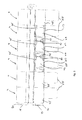
- a first flow path 18 and a second flow path 20 are formed, of which the first flow path 18, for example, the flow and the second flow path 20 forms the return.
- the first flow path 18 is connected to a first hydraulic port 22 and the second flow path 20 is connected to a second hydraulic port 24.
- the first hydraulic Terminal 22 thus forms a flow connection for a load circuit and the second hydraulic connection preferably a return connection for this load circuit.
- a valve 26 is located, via which the free flow cross-section of the first flow path 18 can be adjusted in the first hydraulic port 22.
- the valve 26 forms part of a regulating device and is connected to a drive motor 28.
- the drive motor 28 drives the valve 26 in rotation, via a spindle drive 30, the valve member 32 moves back and forth and by a valve seat 33 out of engagement and back into abutment is movable.
- the first flow path 18 and the second flow path 20 extend in parallel longitudinally through the load module 4 from a first end 34 to an opposite second end 36. At the first end 34, the first flow path 18 and the second flow path 20 terminate in a first one, respectively Hydraulic coupling 38. At the opposite second end 36 of the first flow path 18 and the second flow path 20 terminate in a second hydraulic clutch 40.
- the first hydraulic clutch 38 is formed as a female coupling element, while the second hydraulic clutch 40 each formed as a male coupling element is. However, it would also be a reverse design or axial contact of the couplings to each other possible.
- the second hydraulic couplings 40 of a load module 4 sealingly engage the first hydraulic couplings 38 of an adjacent load module 4, so that through the two load modules 4 through a continuous first flow path 18 and a continuous second flow path 20 are formed.
- the main module 2 is provided with corresponding first hydraulic clutches 38 into which the second hydraulic clutches 38 Clutches 40 of the first load module 4 can engage to establish a hydraulic connection between the first flow path 18 and the second flow path 20 to the corresponding flow paths inside the main module 2 and its terminals 8 and 10 (input 8 and output 10).
- mechanical connections 42 are also provided to mechanically connect the individual load modules 4 together.
- the mechanical connections 42 can be designed in various ways and additionally secured by bolts, clamps, screws or the like.
- the hydraulic clutches 38 and 40 could be formed mechanically stable such that can be dispensed with additional mechanical connections 42.
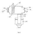
- the load modules 4 each have a printed circuit board 44, which is arranged in the module housing 16 in a receiving space 46.
- the receiving space 46 is closed by a cover 48.
- the circuit board 44 is formed to extend from the first end 34 to the second end 36 of the load module 4.
- the printed circuit board 44 at its first end to a first electrical plug-in coupling 50, which is formed in this example as a female coupling.
- a second electrical plug-in coupling 50 which is formed in this example as a male coupling.
- the first electrical plug-in coupling 50 and the second electrically plug-in coupling 52 are multipolar and complementary to each other, so that the electrical plug contacts of the first eclectic plug-in coupling and the second electrical plug-in coupling 52 of two adjacent load modules 4 can electrically engage with each other.
- the receiving space 46 has for this purpose at the first end 34 and at the second end 36 each have an opening which are not closed by the lid 48, so that adjacent first electrical plug-in couplings 50 and second electrical plug-in couplings 52 can electrically conductively engage with each other.
- the printed circuit boards 44 of adjacent load modules 4 can thus produce a continuous electrical connection between all the load modules 4 lined up in a row.
- conductor tracks are preferably formed on the printed circuit boards 44, which form a bus system, so that all load modules 4 can be supplied with energy and moreover can be controlled by the distributor control device in the electronics housing 1 of the main module 2.
- data communication between the module control devices formed on the printed circuit boards 44 and the distributor control device in the electronics housing 14 is provided via the described bus system.
- the electronic components of the distributor control device are preferably connected to electrical terminals in the main module 2, which electrically conductively communicate with the second electrical plug-in coupling 52 of the first load module 4, which adjoins the main module 2.
- a cable connection may be provided.
- a sensor 53 which can be, for example, an infrared temperature sensor which detects the temperature in the module housing or one of the flow paths, is in each case formed on the printed circuit boards 44.
- the sensor signals detected by the sensor are transmitted by the module control device via the described bus system to the distributor control device.
- the printed circuit boards 44 are resilient in their longitudinal direction from the first end 34 to the second end 36.
- the printed circuit boards 44 each have a meander-shaped elastic section 54.
- This in Fig. 8 characterized resilient or elastic portion 54 is formed in this embodiment by two introduced from opposite sides in the circuit board 44 incisions 56, which lead to a meandering or tortuous course of the circuit board in the elastic portion 54.
- the elastic portion 54 causes the printed circuit board 44 to elastically compress when a compressive force is applied to the first male electrical connector 50 and the second male electrical connector 52. This can ensure that when two load modules 4 are lined up, the plug-in couplings 50 and 52 can safely engage on the one hand and on the other hand there is no plastic deformation or damage to the printed circuit boards 44 in case of excessive force. In addition, so manufacturing tolerances can be compensated.
- the receiving space 46 in which the circuit board 44 is located, completely separated from the flow paths 18 and 20 and the area in which the valve 26 is located.
- the drive motor 28 is arranged in a drive receiving space 58, which also has no direct connection to the receiving space 46, in which the circuit board 44 is located.
- the drive motor or drive 28 is rather connected via a connecting element 60 with the printed circuit board 44.
- the plug direction is directed in this embodiment perpendicular to the direction of insertion of the first electrical coupling 50 and the second eclectic coupling 52.
- connection element 60 engages with corresponding plug contacts 64.
- the connection element extends 60 through an opening 66 into the receiving space 46 into it.
- the opening 66 is not directly facing the interior of the drive receiving space 46, but rather opened to the outside of the module housing 16. This ensures that even with a leak in the valve 46 moisture can not enter directly into the interior of the receiving space 46 via the drive receiving space 48.
- the connection element 60 is fixedly connected to the drive motor 28. However, it should be understood that an additional plug connection could also be provided here.
- the drive receiving space 58 with the drive motor 28 inserted is covered to the outside by a cap 68.
- the cap 68 also covers the connecting element 60.
- load module 4 is used to control a heating or cooling circuit and for this purpose has a valve 26 or optionally a pump.
- load modules 4 can be provided, which are designed to control a plurality of load circuits and for this purpose include a plurality of valves 26 in a module housing 16.
- a single module control device is preferably provided for each of the valves.
- a common module control device may be provided, which controls a plurality of valves 26 and their drive motors 28 individually, wherein the control commands can preferably be transmitted from the main module and disposed in the electronics housing distribution controller to the module control device via the described electrical contacts.
- electrical connections can be arranged in the manner described above, so that these load modules 4 can be strung together or stuck to form the hydraulic distributor.
- each load module 4 has two flow paths, namely the first flow path 18 and the second flow path 20.
- a hydraulic distributor in a corresponding manner, which has more or less than two flow paths.
- the second flow path 20 could be omitted and corresponding hydraulic connections of the connected load circuits could take place in a separate hydraulic distributor.
Landscapes
- Engineering & Computer Science (AREA)
- General Engineering & Computer Science (AREA)
- Mechanical Engineering (AREA)
- Chemical & Material Sciences (AREA)
- Combustion & Propulsion (AREA)
- Physics & Mathematics (AREA)
- Thermal Sciences (AREA)
- Life Sciences & Earth Sciences (AREA)
- Sustainable Development (AREA)
- Steam Or Hot-Water Central Heating Systems (AREA)
- Fluid-Pressure Circuits (AREA)
- Mounting Of Printed Circuit Boards And The Like (AREA)
- Valve Housings (AREA)
Priority Applications (5)
| Application Number | Priority Date | Filing Date | Title |
|---|---|---|---|
| DK15158772.2T DK3067628T3 (en) | 2015-03-12 | 2015-03-12 | Hydraulic valve |
| EP15158772.2A EP3067628B1 (fr) | 2015-03-12 | 2015-03-12 | Vanne hydraulique |
| RU2016108109A RU2633215C2 (ru) | 2015-03-12 | 2016-03-09 | Гидравлический клапан |
| US15/066,313 US10302310B2 (en) | 2015-03-12 | 2016-03-10 | Hydraulic manifold |
| CN201610144855.0A CN105972260B (zh) | 2015-03-12 | 2016-03-14 | 液压阀 |
Applications Claiming Priority (1)
| Application Number | Priority Date | Filing Date | Title |
|---|---|---|---|
| EP15158772.2A EP3067628B1 (fr) | 2015-03-12 | 2015-03-12 | Vanne hydraulique |
Publications (2)
| Publication Number | Publication Date |
|---|---|
| EP3067628A1 true EP3067628A1 (fr) | 2016-09-14 |
| EP3067628B1 EP3067628B1 (fr) | 2018-07-11 |
Family
ID=52684053
Family Applications (1)
| Application Number | Title | Priority Date | Filing Date |
|---|---|---|---|
| EP15158772.2A Not-in-force EP3067628B1 (fr) | 2015-03-12 | 2015-03-12 | Vanne hydraulique |
Country Status (5)
| Country | Link |
|---|---|
| US (1) | US10302310B2 (fr) |
| EP (1) | EP3067628B1 (fr) |
| CN (1) | CN105972260B (fr) |
| DK (1) | DK3067628T3 (fr) |
| RU (1) | RU2633215C2 (fr) |
Cited By (5)
| Publication number | Priority date | Publication date | Assignee | Title |
|---|---|---|---|---|
| DE102017200414A1 (de) | 2017-01-12 | 2018-09-13 | Ifm Electronic Gmbh | Messgerät für die Prozess- und Automatisierungstechnik |
| EP3553395A1 (fr) * | 2018-04-11 | 2019-10-16 | Johnson Electric International AG | Actionneur, collecteur de circuit de chauffage et procédure d'installation d'un actionneur dans un collecteur de circuit de chauffage |
| EP3855054A1 (fr) * | 2020-01-23 | 2021-07-28 | Eugster/Frismag AG | Soupape à voies multiples pour un fluide pour un dispositif de préparation de boisson, soupape à fluides multiples à voies multiples pour un dispositif de préparation de boisson et dispositif de préparation de boisson, en particulier machine à café |
| DE102022115245A1 (de) | 2022-06-20 | 2023-12-21 | Oventrop Gmbh & Co. Kg | Strömungsverteiler für Heizungs- oder Kühlanlagen mit Anschlussteilen |
| EP4306869A1 (fr) * | 2022-07-13 | 2024-01-17 | Kermi GmbH | Baguette de serrage ou de serrage à réglage pour un chauffage de surface, dispositif de fonctionnement d'un chauffage de surface et procédé de mise en service d'un chauffage de surface |
Families Citing this family (2)
| Publication number | Priority date | Publication date | Assignee | Title |
|---|---|---|---|---|
| FR3089273B1 (fr) * | 2018-11-29 | 2022-02-18 | Akwel | Vanne à pointeau modulaire |
| DE102020210496B3 (de) * | 2020-08-19 | 2021-12-16 | Robert Bosch Gesellschaft mit beschränkter Haftung | Adapterstecker und Elektronikbaugruppe mit einem Adapterstecker |
Citations (2)
| Publication number | Priority date | Publication date | Assignee | Title |
|---|---|---|---|---|
| US6345770B1 (en) * | 2001-04-13 | 2002-02-12 | Thomas O. Simensen | Modular manifold |
| DE102006010562A1 (de) * | 2006-03-06 | 2007-09-13 | Wilo Ag | Vorrichtung zum Verteilen und Regeln eines von einer Heiz- und/oder Kühlquelle stammenden Wärmeträgers |
Family Cites Families (12)
| Publication number | Priority date | Publication date | Assignee | Title |
|---|---|---|---|---|
| US4986870A (en) * | 1984-03-09 | 1991-01-22 | R.W.Q., Inc. | Apparatus for laminating multilayered printed circuit boards having both rigid and flexible portions |
| WO1993005296A1 (fr) * | 1991-09-10 | 1993-03-18 | Smc Kabushiki Kaisha | Appareil utilisant la pression d'un fluide |
| DE4330156A1 (de) * | 1993-09-07 | 1995-03-09 | Hkf Heizkoerperfertigung Meini | Rohrverteiler |
| SE9900164D0 (sv) * | 1999-01-20 | 1999-01-20 | Piezomotors Uppsala Ab | Flexible microsystem and building techniques |
| JP3409085B2 (ja) * | 1999-03-31 | 2003-05-19 | エスエムシー株式会社 | シリアル信号駆動のマニホールド形電磁弁 |
| US6357414B1 (en) * | 1999-04-22 | 2002-03-19 | Visteon Global Technologies, Inc. | Air manifold mounting for engine control circuitry |
| US6490172B1 (en) * | 2000-05-23 | 2002-12-03 | Numatics, Incorporated | Circuit board retainer |
| US20030222235A1 (en) * | 2002-06-04 | 2003-12-04 | Filkovski Gregory T. | Modular shut-off valve apparatus |
| DE202005014029U1 (de) * | 2005-09-05 | 2005-11-17 | Comfort-Sinusverteiler Gmbh | Rohrverteiler für eine Heizungs- oder Kühlanlage |
| GB0525157D0 (en) * | 2005-12-09 | 2006-01-18 | Ec Power As | Fluid distributor |
| US7637234B2 (en) * | 2007-08-07 | 2009-12-29 | Scuderi Group, Llc | Split-cycle engine with a helical crossover passage |
| US8326134B2 (en) * | 2009-07-27 | 2012-12-04 | Harper James T | Integrated boiler component wiring assembly and method |
-
2015
- 2015-03-12 DK DK15158772.2T patent/DK3067628T3/en active
- 2015-03-12 EP EP15158772.2A patent/EP3067628B1/fr not_active Not-in-force
-
2016
- 2016-03-09 RU RU2016108109A patent/RU2633215C2/ru active
- 2016-03-10 US US15/066,313 patent/US10302310B2/en active Active
- 2016-03-14 CN CN201610144855.0A patent/CN105972260B/zh not_active Expired - Fee Related
Patent Citations (2)
| Publication number | Priority date | Publication date | Assignee | Title |
|---|---|---|---|---|
| US6345770B1 (en) * | 2001-04-13 | 2002-02-12 | Thomas O. Simensen | Modular manifold |
| DE102006010562A1 (de) * | 2006-03-06 | 2007-09-13 | Wilo Ag | Vorrichtung zum Verteilen und Regeln eines von einer Heiz- und/oder Kühlquelle stammenden Wärmeträgers |
Cited By (7)
| Publication number | Priority date | Publication date | Assignee | Title |
|---|---|---|---|---|
| DE102017200414A1 (de) | 2017-01-12 | 2018-09-13 | Ifm Electronic Gmbh | Messgerät für die Prozess- und Automatisierungstechnik |
| EP3553395A1 (fr) * | 2018-04-11 | 2019-10-16 | Johnson Electric International AG | Actionneur, collecteur de circuit de chauffage et procédure d'installation d'un actionneur dans un collecteur de circuit de chauffage |
| EP3855054A1 (fr) * | 2020-01-23 | 2021-07-28 | Eugster/Frismag AG | Soupape à voies multiples pour un fluide pour un dispositif de préparation de boisson, soupape à fluides multiples à voies multiples pour un dispositif de préparation de boisson et dispositif de préparation de boisson, en particulier machine à café |
| DE102022115245A1 (de) | 2022-06-20 | 2023-12-21 | Oventrop Gmbh & Co. Kg | Strömungsverteiler für Heizungs- oder Kühlanlagen mit Anschlussteilen |
| EP4296582A1 (fr) | 2022-06-20 | 2023-12-27 | Oventrop GmbH & Co. KG | Distributeur d'écoulement pour installations de chauffage ou de refroidissement avec éléments de raccordement |
| EP4306869A1 (fr) * | 2022-07-13 | 2024-01-17 | Kermi GmbH | Baguette de serrage ou de serrage à réglage pour un chauffage de surface, dispositif de fonctionnement d'un chauffage de surface et procédé de mise en service d'un chauffage de surface |
| DE102022207165A1 (de) * | 2022-07-13 | 2024-01-18 | Kermi Gmbh | Regelklemm- oder Klemmleiste für eine Flächenheizung, Anordnung zum Betreiben einer Flächenheizung und Verfahren zur Inbetriebnahme einer Flächenheizung |
Also Published As
| Publication number | Publication date |
|---|---|
| US20160265792A1 (en) | 2016-09-15 |
| US10302310B2 (en) | 2019-05-28 |
| RU2633215C2 (ru) | 2017-10-11 |
| CN105972260B (zh) | 2019-05-28 |
| DK3067628T3 (en) | 2018-10-29 |
| CN105972260A (zh) | 2016-09-28 |
| RU2016108109A (ru) | 2017-09-14 |
| EP3067628B1 (fr) | 2018-07-11 |
Similar Documents
| Publication | Publication Date | Title |
|---|---|---|
| EP3067628B1 (fr) | Vanne hydraulique | |
| EP2871421B1 (fr) | Distributeur hydraulique pour un système de chauffage et/ou de refroidissement hydraulique | |
| EP2871420B1 (fr) | Module de pompe de circulation pour un système de chauffage et/ou de refroidissement | |
| DE60017993T2 (de) | Stromversorgung einer Magnetventilverteilerplatte | |
| DE60036745T2 (de) | Magnetventilblock mit seriellem Datenbus | |
| EP2871422B1 (fr) | Distributeur hydraulique pour un système de chauffage et/ou de refroidissement hydraulique | |
| DE60036747T2 (de) | Magnetventilblock mit seriellem Datenbus | |
| EP2654392B1 (fr) | Module semi-conducteur de puissance refroidi par liquide pouvant être joint et agencement à cet effet | |
| EP3037704B1 (fr) | Vanne mélangeuse | |
| DE102013111867A1 (de) | Anschlusszeile für eine Anschlussvorrichtung | |
| DE60016681T3 (de) | Magnet-Wegeventil für einen Verteilerblock mit einer Relais-Vorrichtung | |
| DE60036656T2 (de) | Magnetventilblock mit seriellem Datenbus | |
| DE19816170C2 (de) | Steuerungsmodul | |
| EP2521432A2 (fr) | Agencement de puissance électronique doté d'un refroidissement de liquide | |
| WO2015144265A1 (fr) | Module de connexion et/ou de fonction compatible avec un bus et pouvant être mis en série | |
| DE102006055411B4 (de) | Lüftungs-, Klima- oder / und Heizungsanlage mit verbesserter Lüftungseinheit | |
| EP2449302B1 (fr) | Agencement d'accouplement | |
| DE102016120027A1 (de) | Ventilanordnung | |
| DE102016120029A1 (de) | Ventilanordnung | |
| EP3067603B1 (fr) | Vanne hydraulique | |
| DE102018108562A1 (de) | Stellantrieb, Heizkreisverteiler und Verfahren zur Montage des Stellantriebes in einem solchen Heizkreisverteiler | |
| DE102015218526B4 (de) | Anschlussanordnung für ein Solarmodul | |
| EP3923417A1 (fr) | Boîte de dérivation | |
| DE3626570C2 (de) | Schaltungsanordnung zur Steuerung einer Warmwasser-Heizungsanlage | |
| EP0698770A1 (fr) | Radiateur |
Legal Events
| Date | Code | Title | Description |
|---|---|---|---|
| PUAI | Public reference made under article 153(3) epc to a published international application that has entered the european phase |
Free format text: ORIGINAL CODE: 0009012 |
|
| AK | Designated contracting states |
Kind code of ref document: A1 Designated state(s): AL AT BE BG CH CY CZ DE DK EE ES FI FR GB GR HR HU IE IS IT LI LT LU LV MC MK MT NL NO PL PT RO RS SE SI SK SM TR |
|
| AX | Request for extension of the european patent |
Extension state: BA ME |
|
| STAA | Information on the status of an ep patent application or granted ep patent |
Free format text: STATUS: REQUEST FOR EXAMINATION WAS MADE |
|
| 17P | Request for examination filed |
Effective date: 20170123 |
|
| RBV | Designated contracting states (corrected) |
Designated state(s): AL AT BE BG CH CY CZ DE DK EE ES FI FR GB GR HR HU IE IS IT LI LT LU LV MC MK MT NL NO PL PT RO RS SE SI SK SM TR |
|
| REG | Reference to a national code |
Ref country code: DE Ref legal event code: R079 Ref document number: 502015004983 Country of ref document: DE Free format text: PREVIOUS MAIN CLASS: F24D0003100000 Ipc: F24F0005000000 |
|
| GRAP | Despatch of communication of intention to grant a patent |
Free format text: ORIGINAL CODE: EPIDOSNIGR1 |
|
| STAA | Information on the status of an ep patent application or granted ep patent |
Free format text: STATUS: GRANT OF PATENT IS INTENDED |
|
| RIC1 | Information provided on ipc code assigned before grant |
Ipc: F24F 5/00 20060101AFI20171115BHEP Ipc: F24D 3/14 20060101ALI20171115BHEP Ipc: F24D 3/10 20060101ALI20171115BHEP Ipc: F24D 3/12 20060101ALI20171115BHEP |
|
| INTG | Intention to grant announced |
Effective date: 20171220 |
|
| GRAS | Grant fee paid |
Free format text: ORIGINAL CODE: EPIDOSNIGR3 |
|
| GRAJ | Information related to disapproval of communication of intention to grant by the applicant or resumption of examination proceedings by the epo deleted |
Free format text: ORIGINAL CODE: EPIDOSDIGR1 |
|
| GRAL | Information related to payment of fee for publishing/printing deleted |
Free format text: ORIGINAL CODE: EPIDOSDIGR3 |
|
| STAA | Information on the status of an ep patent application or granted ep patent |
Free format text: STATUS: REQUEST FOR EXAMINATION WAS MADE |
|
| GRAR | Information related to intention to grant a patent recorded |
Free format text: ORIGINAL CODE: EPIDOSNIGR71 |
|
| STAA | Information on the status of an ep patent application or granted ep patent |
Free format text: STATUS: GRANT OF PATENT IS INTENDED |
|
| INTC | Intention to grant announced (deleted) | ||
| GRAA | (expected) grant |
Free format text: ORIGINAL CODE: 0009210 |
|
| STAA | Information on the status of an ep patent application or granted ep patent |
Free format text: STATUS: THE PATENT HAS BEEN GRANTED |
|
| AK | Designated contracting states |
Kind code of ref document: B1 Designated state(s): AL AT BE BG CH CY CZ DE DK EE ES FI FR GB GR HR HU IE IS IT LI LT LU LV MC MK MT NL NO PL PT RO RS SE SI SK SM TR |
|
| INTG | Intention to grant announced |
Effective date: 20180605 |
|
| REG | Reference to a national code |
Ref country code: GB Ref legal event code: FG4D Free format text: NOT ENGLISH |
|
| REG | Reference to a national code |
Ref country code: CH Ref legal event code: EP |
|
| REG | Reference to a national code |
Ref country code: AT Ref legal event code: REF Ref document number: 1017281 Country of ref document: AT Kind code of ref document: T Effective date: 20180715 |
|
| REG | Reference to a national code |
Ref country code: IE Ref legal event code: FG4D Free format text: LANGUAGE OF EP DOCUMENT: GERMAN |
|
| REG | Reference to a national code |
Ref country code: DE Ref legal event code: R096 Ref document number: 502015004983 Country of ref document: DE |
|
| REG | Reference to a national code |
Ref country code: NL Ref legal event code: FP |
|
| REG | Reference to a national code |
Ref country code: DK Ref legal event code: T3 Effective date: 20181016 |
|
| REG | Reference to a national code |
Ref country code: LT Ref legal event code: MG4D |
|
| PG25 | Lapsed in a contracting state [announced via postgrant information from national office to epo] |
Ref country code: FI Free format text: LAPSE BECAUSE OF FAILURE TO SUBMIT A TRANSLATION OF THE DESCRIPTION OR TO PAY THE FEE WITHIN THE PRESCRIBED TIME-LIMIT Effective date: 20180711 Ref country code: RS Free format text: LAPSE BECAUSE OF FAILURE TO SUBMIT A TRANSLATION OF THE DESCRIPTION OR TO PAY THE FEE WITHIN THE PRESCRIBED TIME-LIMIT Effective date: 20180711 Ref country code: GR Free format text: LAPSE BECAUSE OF FAILURE TO SUBMIT A TRANSLATION OF THE DESCRIPTION OR TO PAY THE FEE WITHIN THE PRESCRIBED TIME-LIMIT Effective date: 20181012 Ref country code: IS Free format text: LAPSE BECAUSE OF FAILURE TO SUBMIT A TRANSLATION OF THE DESCRIPTION OR TO PAY THE FEE WITHIN THE PRESCRIBED TIME-LIMIT Effective date: 20181111 Ref country code: NO Free format text: LAPSE BECAUSE OF FAILURE TO SUBMIT A TRANSLATION OF THE DESCRIPTION OR TO PAY THE FEE WITHIN THE PRESCRIBED TIME-LIMIT Effective date: 20181011 Ref country code: SE Free format text: LAPSE BECAUSE OF FAILURE TO SUBMIT A TRANSLATION OF THE DESCRIPTION OR TO PAY THE FEE WITHIN THE PRESCRIBED TIME-LIMIT Effective date: 20180711 Ref country code: BG Free format text: LAPSE BECAUSE OF FAILURE TO SUBMIT A TRANSLATION OF THE DESCRIPTION OR TO PAY THE FEE WITHIN THE PRESCRIBED TIME-LIMIT Effective date: 20181011 Ref country code: LT Free format text: LAPSE BECAUSE OF FAILURE TO SUBMIT A TRANSLATION OF THE DESCRIPTION OR TO PAY THE FEE WITHIN THE PRESCRIBED TIME-LIMIT Effective date: 20180711 Ref country code: PL Free format text: LAPSE BECAUSE OF FAILURE TO SUBMIT A TRANSLATION OF THE DESCRIPTION OR TO PAY THE FEE WITHIN THE PRESCRIBED TIME-LIMIT Effective date: 20180711 |
|
| PG25 | Lapsed in a contracting state [announced via postgrant information from national office to epo] |
Ref country code: HR Free format text: LAPSE BECAUSE OF FAILURE TO SUBMIT A TRANSLATION OF THE DESCRIPTION OR TO PAY THE FEE WITHIN THE PRESCRIBED TIME-LIMIT Effective date: 20180711 Ref country code: LV Free format text: LAPSE BECAUSE OF FAILURE TO SUBMIT A TRANSLATION OF THE DESCRIPTION OR TO PAY THE FEE WITHIN THE PRESCRIBED TIME-LIMIT Effective date: 20180711 Ref country code: AL Free format text: LAPSE BECAUSE OF FAILURE TO SUBMIT A TRANSLATION OF THE DESCRIPTION OR TO PAY THE FEE WITHIN THE PRESCRIBED TIME-LIMIT Effective date: 20180711 |
|
| REG | Reference to a national code |
Ref country code: DE Ref legal event code: R097 Ref document number: 502015004983 Country of ref document: DE |
|
| PG25 | Lapsed in a contracting state [announced via postgrant information from national office to epo] |
Ref country code: CZ Free format text: LAPSE BECAUSE OF FAILURE TO SUBMIT A TRANSLATION OF THE DESCRIPTION OR TO PAY THE FEE WITHIN THE PRESCRIBED TIME-LIMIT Effective date: 20180711 Ref country code: ES Free format text: LAPSE BECAUSE OF FAILURE TO SUBMIT A TRANSLATION OF THE DESCRIPTION OR TO PAY THE FEE WITHIN THE PRESCRIBED TIME-LIMIT Effective date: 20180711 Ref country code: RO Free format text: LAPSE BECAUSE OF FAILURE TO SUBMIT A TRANSLATION OF THE DESCRIPTION OR TO PAY THE FEE WITHIN THE PRESCRIBED TIME-LIMIT Effective date: 20180711 Ref country code: IT Free format text: LAPSE BECAUSE OF FAILURE TO SUBMIT A TRANSLATION OF THE DESCRIPTION OR TO PAY THE FEE WITHIN THE PRESCRIBED TIME-LIMIT Effective date: 20180711 Ref country code: EE Free format text: LAPSE BECAUSE OF FAILURE TO SUBMIT A TRANSLATION OF THE DESCRIPTION OR TO PAY THE FEE WITHIN THE PRESCRIBED TIME-LIMIT Effective date: 20180711 |
|
| PLBE | No opposition filed within time limit |
Free format text: ORIGINAL CODE: 0009261 |
|
| STAA | Information on the status of an ep patent application or granted ep patent |
Free format text: STATUS: NO OPPOSITION FILED WITHIN TIME LIMIT |
|
| PG25 | Lapsed in a contracting state [announced via postgrant information from national office to epo] |
Ref country code: SM Free format text: LAPSE BECAUSE OF FAILURE TO SUBMIT A TRANSLATION OF THE DESCRIPTION OR TO PAY THE FEE WITHIN THE PRESCRIBED TIME-LIMIT Effective date: 20180711 Ref country code: SK Free format text: LAPSE BECAUSE OF FAILURE TO SUBMIT A TRANSLATION OF THE DESCRIPTION OR TO PAY THE FEE WITHIN THE PRESCRIBED TIME-LIMIT Effective date: 20180711 |
|
| 26N | No opposition filed |
Effective date: 20190412 |
|
| PG25 | Lapsed in a contracting state [announced via postgrant information from national office to epo] |
Ref country code: SI Free format text: LAPSE BECAUSE OF FAILURE TO SUBMIT A TRANSLATION OF THE DESCRIPTION OR TO PAY THE FEE WITHIN THE PRESCRIBED TIME-LIMIT Effective date: 20180711 |
|
| PG25 | Lapsed in a contracting state [announced via postgrant information from national office to epo] |
Ref country code: MC Free format text: LAPSE BECAUSE OF FAILURE TO SUBMIT A TRANSLATION OF THE DESCRIPTION OR TO PAY THE FEE WITHIN THE PRESCRIBED TIME-LIMIT Effective date: 20180711 |
|
| REG | Reference to a national code |
Ref country code: CH Ref legal event code: PL |
|
| PG25 | Lapsed in a contracting state [announced via postgrant information from national office to epo] |
Ref country code: LU Free format text: LAPSE BECAUSE OF NON-PAYMENT OF DUE FEES Effective date: 20190312 |
|
| REG | Reference to a national code |
Ref country code: BE Ref legal event code: MM Effective date: 20190331 |
|
| PG25 | Lapsed in a contracting state [announced via postgrant information from national office to epo] |
Ref country code: LI Free format text: LAPSE BECAUSE OF NON-PAYMENT OF DUE FEES Effective date: 20190331 Ref country code: CH Free format text: LAPSE BECAUSE OF NON-PAYMENT OF DUE FEES Effective date: 20190331 Ref country code: IE Free format text: LAPSE BECAUSE OF NON-PAYMENT OF DUE FEES Effective date: 20190312 |
|
| PG25 | Lapsed in a contracting state [announced via postgrant information from national office to epo] |
Ref country code: BE Free format text: LAPSE BECAUSE OF NON-PAYMENT OF DUE FEES Effective date: 20190331 |
|
| PG25 | Lapsed in a contracting state [announced via postgrant information from national office to epo] |
Ref country code: TR Free format text: LAPSE BECAUSE OF FAILURE TO SUBMIT A TRANSLATION OF THE DESCRIPTION OR TO PAY THE FEE WITHIN THE PRESCRIBED TIME-LIMIT Effective date: 20180711 |
|
| PG25 | Lapsed in a contracting state [announced via postgrant information from national office to epo] |
Ref country code: MT Free format text: LAPSE BECAUSE OF FAILURE TO SUBMIT A TRANSLATION OF THE DESCRIPTION OR TO PAY THE FEE WITHIN THE PRESCRIBED TIME-LIMIT Effective date: 20180711 Ref country code: PT Free format text: LAPSE BECAUSE OF FAILURE TO SUBMIT A TRANSLATION OF THE DESCRIPTION OR TO PAY THE FEE WITHIN THE PRESCRIBED TIME-LIMIT Effective date: 20181111 |
|
| REG | Reference to a national code |
Ref country code: AT Ref legal event code: MM01 Ref document number: 1017281 Country of ref document: AT Kind code of ref document: T Effective date: 20200312 |
|
| PG25 | Lapsed in a contracting state [announced via postgrant information from national office to epo] |
Ref country code: CY Free format text: LAPSE BECAUSE OF FAILURE TO SUBMIT A TRANSLATION OF THE DESCRIPTION OR TO PAY THE FEE WITHIN THE PRESCRIBED TIME-LIMIT Effective date: 20180711 |
|
| PG25 | Lapsed in a contracting state [announced via postgrant information from national office to epo] |
Ref country code: HU Free format text: LAPSE BECAUSE OF FAILURE TO SUBMIT A TRANSLATION OF THE DESCRIPTION OR TO PAY THE FEE WITHIN THE PRESCRIBED TIME-LIMIT; INVALID AB INITIO Effective date: 20150312 |
|
| PG25 | Lapsed in a contracting state [announced via postgrant information from national office to epo] |
Ref country code: AT Free format text: LAPSE BECAUSE OF NON-PAYMENT OF DUE FEES Effective date: 20200312 |
|
| PG25 | Lapsed in a contracting state [announced via postgrant information from national office to epo] |
Ref country code: MK Free format text: LAPSE BECAUSE OF FAILURE TO SUBMIT A TRANSLATION OF THE DESCRIPTION OR TO PAY THE FEE WITHIN THE PRESCRIBED TIME-LIMIT Effective date: 20180711 |
|
| REG | Reference to a national code |
Ref country code: DE Ref legal event code: R082 Ref document number: 502015004983 Country of ref document: DE |
|
| PGFP | Annual fee paid to national office [announced via postgrant information from national office to epo] |
Ref country code: FR Payment date: 20230324 Year of fee payment: 9 Ref country code: DK Payment date: 20230323 Year of fee payment: 9 |
|
| PGFP | Annual fee paid to national office [announced via postgrant information from national office to epo] |
Ref country code: GB Payment date: 20230322 Year of fee payment: 9 Ref country code: DE Payment date: 20230321 Year of fee payment: 9 |
|
| PGFP | Annual fee paid to national office [announced via postgrant information from national office to epo] |
Ref country code: NL Payment date: 20230321 Year of fee payment: 9 |
|
| REG | Reference to a national code |
Ref country code: DE Ref legal event code: R119 Ref document number: 502015004983 Country of ref document: DE |
|
| REG | Reference to a national code |
Ref country code: DK Ref legal event code: EBP Effective date: 20240331 |
|
| REG | Reference to a national code |
Ref country code: NL Ref legal event code: MM Effective date: 20240401 |
|
| GBPC | Gb: european patent ceased through non-payment of renewal fee |
Effective date: 20240312 |
|
| PG25 | Lapsed in a contracting state [announced via postgrant information from national office to epo] |
Ref country code: NL Free format text: LAPSE BECAUSE OF NON-PAYMENT OF DUE FEES Effective date: 20240401 |
|
| PG25 | Lapsed in a contracting state [announced via postgrant information from national office to epo] |
Ref country code: NL Free format text: LAPSE BECAUSE OF NON-PAYMENT OF DUE FEES Effective date: 20240401 |
|
| PG25 | Lapsed in a contracting state [announced via postgrant information from national office to epo] |
Ref country code: DE Free format text: LAPSE BECAUSE OF NON-PAYMENT OF DUE FEES Effective date: 20241001 |
|
| PG25 | Lapsed in a contracting state [announced via postgrant information from national office to epo] |
Ref country code: GB Free format text: LAPSE BECAUSE OF NON-PAYMENT OF DUE FEES Effective date: 20240312 |
|
| PG25 | Lapsed in a contracting state [announced via postgrant information from national office to epo] |
Ref country code: FR Free format text: LAPSE BECAUSE OF NON-PAYMENT OF DUE FEES Effective date: 20240331 |
|
| PG25 | Lapsed in a contracting state [announced via postgrant information from national office to epo] |
Ref country code: GB Free format text: LAPSE BECAUSE OF NON-PAYMENT OF DUE FEES Effective date: 20240312 Ref country code: FR Free format text: LAPSE BECAUSE OF NON-PAYMENT OF DUE FEES Effective date: 20240331 Ref country code: DE Free format text: LAPSE BECAUSE OF NON-PAYMENT OF DUE FEES Effective date: 20241001 |
|
| PG25 | Lapsed in a contracting state [announced via postgrant information from national office to epo] |
Ref country code: DK Free format text: LAPSE BECAUSE OF NON-PAYMENT OF DUE FEES Effective date: 20240331 |