EP3068001A1 - Bougie d'allumage - Google Patents
Bougie d'allumage Download PDFInfo
- Publication number
- EP3068001A1 EP3068001A1 EP16450005.0A EP16450005A EP3068001A1 EP 3068001 A1 EP3068001 A1 EP 3068001A1 EP 16450005 A EP16450005 A EP 16450005A EP 3068001 A1 EP3068001 A1 EP 3068001A1
- Authority
- EP
- European Patent Office
- Prior art keywords
- spark plug
- plug according
- electrode
- holder plate
- space
- Prior art date
- Legal status (The legal status is an assumption and is not a legal conclusion. Google has not performed a legal analysis and makes no representation as to the accuracy of the status listed.)
- Withdrawn
Links
- 238000002485 combustion reaction Methods 0.000 claims abstract description 12
- 230000006835 compression Effects 0.000 claims description 5
- 238000007906 compression Methods 0.000 claims description 5
- 239000010970 precious metal Substances 0.000 claims description 3
- 229910000510 noble metal Inorganic materials 0.000 claims description 2
- 238000003466 welding Methods 0.000 claims description 2
- 239000011248 coating agent Substances 0.000 claims 1
- 238000000576 coating method Methods 0.000 claims 1
- 239000000567 combustion gas Substances 0.000 description 16
- 239000000203 mixture Substances 0.000 description 16
- 239000007789 gas Substances 0.000 description 9
- 239000012212 insulator Substances 0.000 description 6
- 239000000463 material Substances 0.000 description 3
- 239000000919 ceramic Substances 0.000 description 2
- 239000000446 fuel Substances 0.000 description 2
- 230000008646 thermal stress Effects 0.000 description 2
- 238000007664 blowing Methods 0.000 description 1
- 238000001816 cooling Methods 0.000 description 1
- 230000003247 decreasing effect Effects 0.000 description 1
- 230000001419 dependent effect Effects 0.000 description 1
- 230000037431 insertion Effects 0.000 description 1
- 238000003780 insertion Methods 0.000 description 1
- 239000006228 supernatant Substances 0.000 description 1
Images

Classifications
-
- H—ELECTRICITY
- H01—ELECTRIC ELEMENTS
- H01T—SPARK GAPS; OVERVOLTAGE ARRESTERS USING SPARK GAPS; SPARKING PLUGS; CORONA DEVICES; GENERATING IONS TO BE INTRODUCED INTO NON-ENCLOSED GASES
- H01T13/00—Sparking plugs
- H01T13/54—Sparking plugs having electrodes arranged in a partly-enclosed ignition chamber
-
- H—ELECTRICITY
- H01—ELECTRIC ELEMENTS
- H01T—SPARK GAPS; OVERVOLTAGE ARRESTERS USING SPARK GAPS; SPARKING PLUGS; CORONA DEVICES; GENERATING IONS TO BE INTRODUCED INTO NON-ENCLOSED GASES
- H01T13/00—Sparking plugs
- H01T13/20—Sparking plugs characterised by features of the electrodes or insulation
- H01T13/32—Sparking plugs characterised by features of the electrodes or insulation characterised by features of the earthed electrode
-
- H—ELECTRICITY
- H01—ELECTRIC ELEMENTS
- H01T—SPARK GAPS; OVERVOLTAGE ARRESTERS USING SPARK GAPS; SPARKING PLUGS; CORONA DEVICES; GENERATING IONS TO BE INTRODUCED INTO NON-ENCLOSED GASES
- H01T13/00—Sparking plugs
- H01T13/46—Sparking plugs having two or more spark gaps
- H01T13/467—Sparking plugs having two or more spark gaps in parallel connection
Definitions
- the invention relates to a spark plug for internal combustion engines according to the preamble of claim 1.
- Spark plugs for internal combustion engines are exposed to high thermal loads and are intended to ignite a combustion gas mixture in the engine over a long service life at the desired time. Due to steadily decreasing emission limits by the legislator, spark plugs have to guarantee an ignition in the combustion chamber with increasingly lean combustion gas mixtures. However, lean combustion gas mixtures are not particularly willing to ignite and present developers of combustion gas engines and spark plug producers with particular challenges.
- Spark plugs for use with lean combustion gas mixtures are, for example, from AT 511 609 B1 known.
- electrodes made of special materials such as conductive ceramics or precious metals are used. These materials should keep the resistance values between the electrodes at high thermal loads as low as possible and guarantee an optimal ignition spark.
- Object of the present invention is to provide a spark plug, which ensures optimal ignition especially for lean combustion gas mixtures.
- a planar, preferably flat, separating element is arranged in the region of the electrodes, which has connecting openings.
- connection openings allow a gas exchange between the storage space behind the separating element and the pre-chamber space in front of the separating element.
- existing exhaust gas which is still in the prechamber space, is forced out of the prechamber space through the connection openings into the storage space during the compression stroke.
- the separating element is designed in a preferred embodiment of the invention as an electrode holder plate and has a centrally disposed opening for the center electrode. Between the electrode holder plate and the central electrode arranged in the central opening there is a spark gap. In this case, the electrode holder plate forms the negative pole and the center electrode forms the positive pole.
- the ignition gap can also be open to the storage space according to the invention.
- a separating element separate from the electrodes may be provided.
- the separating element is preferably arranged behind the electrodes on the side of the storage space of the spark plug.
- the total area of the openings connecting the storage space and the antechamber space amounts to a maximum of 50% of the total area of the separating element. This limitation of the total area prevents the compressed exhaust gas from flowing back into the pre-chamber space and impairing the ignitability of the fresh combustion gas mixture.
- the ratio of the volume of the pre-chamber space to the volume of the storage space in the compression ratio of the internal combustion engine in particular in the ratio 1: 8 until 1:14 lies.
- the ratio may also be smaller or larger than the compression ratio, depending on the prevailing or desired conditions, and deviations of up to or more than 10% or 20% are possible.
- the electrode holder plate can be designed in several parts, in particular in two parts.
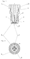
- FIGS. 1 to 6 the front part of a spark plug 1 according to the invention is shown in two preferred embodiments.
- a non-current-conducting insulator 2 preferably made of ceramic, separates a spark plug housing 15 and a rod electrode 3 extending along a central axis 17 structurally and electrically from one another.
- the portion of the spark plug 1 in which the stick electrode 3 is located is referred to as the front portion of the spark plug 1.
- a spark plug thread 4 located in the front area on the spark plug housing 15, located in the front area on the spark plug housing 15, a spark plug thread 4. In a stepped,
- Recessed portion 16 of the spark plug housing 15 is a separating element, which is designed in the illustrated embodiments as an electrode holder plate 8 with at least one connection opening 9. In the embodiments, four connection openings 9 are provided.
- the connecting openings 9 connect a storage space 11 in the spark plug housing 15 with a pre-chamber space 14 on the opposite side of the electrode holder plate 8.
- a ground electrode 7 located on the electrode holder plate 8, a ground electrode 7. In order to prevent a pressure loss in the cylinder in the installed state of the spark plug is located between the spark plug housing 15 and the insulator 2 a seal. 5
- a differently shaped holder for the ground electrode 7 may be provided or the ground electrodes 7, as is customary in the prior art, be attached to the spark plug housing 15.
- a separate, e.g. plate-shaped, separating element provided, which is preferably arranged behind the electrodes on the side of the storage space.
- a first preferred embodiment of the spark plug 1 according to the invention is shown.
- the insulator 2 ends before the recessed area 16, in which the rod electrode 3 from the electrode holder plate is surrounded.
- the region 16 is arranged so that the supernatant 18 between the spark plug thread 4 and the electrode holder plate 8 as narrow and close to the thread 4 is designed to best ensure a heat conduction from the electrode holder plate 8 via the spark plug thread 4 to a cylinder head in the installed state.
- the storage space 11 behind the electrode holder plate 8 is limited by the spark plug housing 15, the insulator 2 and by the seal 5.
- Fig. 2 shows the electrode holder plate 8 with the connection openings 9 in the installed state.
- the center electrode 6 forms the positive pole and has the shape of a circular disk, but may also have the shape of a polygon or a star-shaped plate with rod-shaped projections.
- the center electrode 6 is spaced from the surrounding ground electrode 7 by a spark gap 10.
- the ground electrode 7 can be designed so that the separating element itself forms the ground electrode 7. However, particularly preferred is when the ground electrode 7 is a ring which is fixed to the electrode holder plate 8, as in Fig. 2 you can see.
- the ground electrode 7 and the center electrode 6 are made of materials such as precious metal or are coated with a noble metal that withstands the thermal stresses and has a low resistance at high temperatures.
- the connecting openings 9 between the storage space 11 and the pre-chamber space 14 are preferably circular arc-shaped and arranged at equal angular intervals to one another in the separating element or in the electrode holder plate 8.
- the pre-chamber space 14 is by a in the Fig. 6 illustrated pre-chamber housing 20 is formed, with which the spark plug 1 is screwed so that the front end of the spark plug forms part of the boundary of the pre-chamber space.
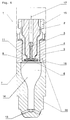
- the Fig. 3 to 5 show a second preferred embodiment of the spark plug according to the invention 1.
- the pre-chamber space 14 is not formed by screwing the spark plug with a pre-chamber housing 20, but that the pre-chamber space 14 is formed by an inextricably attached to the spark plug 1 Vorhuntkuppe 12.
- the Vorhuntkuppe 12 is attached to the spark plug housing 15, for example by welding.
- the Vorschkuppe 12 is arranged on the front side of the spark plug 1 that the screwing of the spark plug 1 is not hindered in the thread on the cylinder head.
- an end-side, coaxially arranged opening 13 and four radially outwardly leading openings 13 are present. Through these openings 13, the fresh combustion gas mixture can flow into the pre-chamber space 14 or escape combustion gases again. Furthermore, the ignition flames pass through these openings 13 into the combustion chamber of the engine.
- Fig. 5 is a detailed drawing of the inserted and fixed by the Vorhuntkuppe 12 electrode holder plate 8 and the connecting openings 9, the rod electrode 3, the center electrode 6, the ignition gap 10 and the ground electrode 7 is shown enlarged.
- the insulator 2 and the electrode holder plate 8 are arranged to one another such that the ignition gap 10 is open to the storage space 11 so that gas can flow from the storage space 11 into the pre-chamber space 14 and vice versa.
- the stepped portion 16 is formed so that after insertion of the electrode holder plate 8 still protrudes a projection 18. In the stepped portion 16 with the projection 18 engages a gradation 19 at the periphery of the Vorschkuppe 12 for centering.
- a particular advantage of an antechamber is that less pre-chamber 14 turbulence than in the cylinder and thus reduces the risk that the spark is blown out, is reduced. Also, the fuel concentration in the pre-chamber 14 can be increased by additionally supplied fuel, which further facilitates the ignition.
- Fig. 6 is the spark plug 1 according to the invention in one Vorhuntgeophuse 20 shown in section along the central axis 17.
- the pre-chamber housing 20 takes over their function.
- the pre-chamber housing 20 is preferably made of two interconnected parts. In the upper, good heat conducting part, the spark plug 1 is screwed, wherein the upper part is designed so that the threaded connection between the thread 4 of the spark plug 1 and the thread of the prechamber housing 20 at least up to the height of the electrode holder plate 8 is sufficient to good cooling to ensure this.
- the lower part of the prechamber housing protrudes into the combustion chamber of the engine cylinder.
- the volume ratio of the prechamber 14 to the storage chamber 11 again corresponds approximately to the engine compression ratio as in the embodiment with a Vorschkuppe 12. About the radially outwardly leading openings 13 takes place as in the Vorschkuppe 12, the gas exchange and the ignition of the fresh combustion gas mixture.
- the variant with a pre-chamber housing 20 according to Fig. 6 is mainly used for large engines.
Landscapes
- Ignition Installations For Internal Combustion Engines (AREA)
- Spark Plugs (AREA)
Applications Claiming Priority (1)
| Application Number | Priority Date | Filing Date | Title |
|---|---|---|---|
| ATA141/2015A AT516835B1 (de) | 2015-03-13 | 2015-03-13 | Zündkerze |
Publications (1)
| Publication Number | Publication Date |
|---|---|
| EP3068001A1 true EP3068001A1 (fr) | 2016-09-14 |
Family
ID=55542621
Family Applications (1)
| Application Number | Title | Priority Date | Filing Date |
|---|---|---|---|
| EP16450005.0A Withdrawn EP3068001A1 (fr) | 2015-03-13 | 2016-03-10 | Bougie d'allumage |
Country Status (2)
| Country | Link |
|---|---|
| EP (1) | EP3068001A1 (fr) |
| AT (1) | AT516835B1 (fr) |
Cited By (7)
| Publication number | Priority date | Publication date | Assignee | Title |
|---|---|---|---|---|
| WO2019141728A1 (fr) * | 2018-01-18 | 2019-07-25 | Elias Russegger | Dispositif d'allumage pour moteur à gaz |
| US10598130B2 (en) | 2017-12-06 | 2020-03-24 | Federal-Mogul Ignition Gmbh | Spark plug with supply passage for fuel, and a system with same |
| WO2020124103A1 (fr) | 2018-12-21 | 2020-06-25 | Innio Jenbacher Gmbh & Co Og | Bougie d'allumage et procédé de fabrication d'une bougie d'allumage |
| WO2021253061A1 (fr) | 2020-06-18 | 2021-12-23 | Innio Jenbacher Gmbh & Co Og | Procédé de fabrication d'un ensemble pour une bougie d'allumage et bougie d'allumage |
| EP3934033A1 (fr) * | 2020-07-03 | 2022-01-05 | Sparkx GmbH | Bougie d'allumage de chambre de précombustion, procédé de fabrication d'une telle bougie d'allumage de chambre de précombustion, ainsi que moteur à combustion interne comprenant une telle bougie d'allumage de chambre de précombustion |
| WO2022242861A1 (fr) * | 2021-05-20 | 2022-11-24 | Robert Bosch Gmbh | Bougie d'allumage de pré-chambre |
| JP2022551824A (ja) * | 2019-10-15 | 2022-12-14 | インニオ ジェンバッハー ゲーエムベーハー アンド コー オーゲー | スパークプラグ及びスパークプラグの作製方法 |
Families Citing this family (1)
| Publication number | Priority date | Publication date | Assignee | Title |
|---|---|---|---|---|
| EP3923427B1 (fr) | 2020-06-09 | 2024-04-03 | Elias Russegger | Bougie d'allumage du moteur à gaz |
Citations (6)
| Publication number | Priority date | Publication date | Assignee | Title |
|---|---|---|---|---|
| EP0675272A1 (fr) * | 1994-03-29 | 1995-10-04 | Dieter Dr. Kuhnert | Dispositif d'allumage à préchambre |
| US20070069617A1 (en) * | 2004-06-24 | 2007-03-29 | Tozzi Luigi P | Pre-chamber spark plug |
| US20110062850A1 (en) * | 2009-09-11 | 2011-03-17 | Woodward Governor Company | Pre-Chamber Spark Plug and Electrodes Therefor |
| DE102011053530A1 (de) * | 2010-11-23 | 2012-05-24 | Woodward, Inc. | Vorkammerzündkerze mit rohrförmiger elektrode und verfahrenzur herstellung derselben |
| AT511609B1 (de) | 2011-07-19 | 2013-01-15 | Ge Jenbacher Gmbh & Co Ohg | Zündkerze für eine brennkraftmaschine |
| US8839762B1 (en) * | 2013-06-10 | 2014-09-23 | Woodward, Inc. | Multi-chamber igniter |
Family Cites Families (2)
| Publication number | Priority date | Publication date | Assignee | Title |
|---|---|---|---|---|
| DE3175871D1 (en) * | 1981-06-16 | 1987-02-26 | Kirkhouse Jet Plug Pty | Spark plug |
| EP1701419A1 (fr) * | 2005-03-08 | 2006-09-13 | Veenstra- Glazenborg B.V. | Bougie d'allumage munie d'une préchambre et moteur à combustion interne comportant une bougie d'allumage munie d'une préchambre |
-
2015
- 2015-03-13 AT ATA141/2015A patent/AT516835B1/de not_active IP Right Cessation
-
2016
- 2016-03-10 EP EP16450005.0A patent/EP3068001A1/fr not_active Withdrawn
Patent Citations (6)
| Publication number | Priority date | Publication date | Assignee | Title |
|---|---|---|---|---|
| EP0675272A1 (fr) * | 1994-03-29 | 1995-10-04 | Dieter Dr. Kuhnert | Dispositif d'allumage à préchambre |
| US20070069617A1 (en) * | 2004-06-24 | 2007-03-29 | Tozzi Luigi P | Pre-chamber spark plug |
| US20110062850A1 (en) * | 2009-09-11 | 2011-03-17 | Woodward Governor Company | Pre-Chamber Spark Plug and Electrodes Therefor |
| DE102011053530A1 (de) * | 2010-11-23 | 2012-05-24 | Woodward, Inc. | Vorkammerzündkerze mit rohrförmiger elektrode und verfahrenzur herstellung derselben |
| AT511609B1 (de) | 2011-07-19 | 2013-01-15 | Ge Jenbacher Gmbh & Co Ohg | Zündkerze für eine brennkraftmaschine |
| US8839762B1 (en) * | 2013-06-10 | 2014-09-23 | Woodward, Inc. | Multi-chamber igniter |
Cited By (12)
| Publication number | Priority date | Publication date | Assignee | Title |
|---|---|---|---|---|
| US10598130B2 (en) | 2017-12-06 | 2020-03-24 | Federal-Mogul Ignition Gmbh | Spark plug with supply passage for fuel, and a system with same |
| WO2019141728A1 (fr) * | 2018-01-18 | 2019-07-25 | Elias Russegger | Dispositif d'allumage pour moteur à gaz |
| WO2020124103A1 (fr) | 2018-12-21 | 2020-06-25 | Innio Jenbacher Gmbh & Co Og | Bougie d'allumage et procédé de fabrication d'une bougie d'allumage |
| JP2022551824A (ja) * | 2019-10-15 | 2022-12-14 | インニオ ジェンバッハー ゲーエムベーハー アンド コー オーゲー | スパークプラグ及びスパークプラグの作製方法 |
| JP7228749B2 (ja) | 2019-10-15 | 2023-02-24 | インニオ ジェンバッハー ゲーエムベーハー アンド コー オーゲー | スパークプラグ及びスパークプラグの作製方法 |
| US11855417B2 (en) | 2019-10-15 | 2023-12-26 | Innio Jenbacher Gmbh & Co Og | Spark plug and method for producing a spark plug |
| US12027825B1 (en) | 2019-10-15 | 2024-07-02 | Innio Jenbacher Gmbh & Co Og | Spark plug and method for producing a spark plug |
| WO2021253061A1 (fr) | 2020-06-18 | 2021-12-23 | Innio Jenbacher Gmbh & Co Og | Procédé de fabrication d'un ensemble pour une bougie d'allumage et bougie d'allumage |
| US12027828B2 (en) | 2020-06-18 | 2024-07-02 | Innio Jenbacher Gmbh & Co Og | Method for manufacturing an assembly for a spark plug and spark plug |
| EP3934033A1 (fr) * | 2020-07-03 | 2022-01-05 | Sparkx GmbH | Bougie d'allumage de chambre de précombustion, procédé de fabrication d'une telle bougie d'allumage de chambre de précombustion, ainsi que moteur à combustion interne comprenant une telle bougie d'allumage de chambre de précombustion |
| WO2022002536A1 (fr) * | 2020-07-03 | 2022-01-06 | SparkX GmbH | Bougies d'allumage de préchambre, procédé de fabrication de ce type de bougies d'allumage de préchambre et moteur à combustion interne comprenant ce type de bougie d'allumage de préchambre |
| WO2022242861A1 (fr) * | 2021-05-20 | 2022-11-24 | Robert Bosch Gmbh | Bougie d'allumage de pré-chambre |
Also Published As
| Publication number | Publication date |
|---|---|
| AT516835A4 (de) | 2016-09-15 |
| AT516835B1 (de) | 2016-09-15 |
Similar Documents
| Publication | Publication Date | Title |
|---|---|---|
| AT516835B1 (de) | Zündkerze | |
| EP3281263B1 (fr) | Bougie d'allumage | |
| EP3493340B1 (fr) | Bougie d'allumage pourvue de logement allongé et d'électrode de masse sur la face intérieure du logement | |
| EP3123575B1 (fr) | Bougie d'allumage de préchambre pour allumer un mélange air-carburant dans un moteur à combustion interne | |
| DE102017107679B4 (de) | Vorkammerzündkerze für eine Brennkraftmaschine | |
| DE102017107728A1 (de) | Vorkammerzündkerze und Verfahren zu deren Herstellung | |
| DE102018130539B4 (de) | Vorkammer- Zündkerzenanordnung | |
| DE102014004943A1 (de) | Vorkammerzündkerze | |
| EP2517323B1 (fr) | Bougie d'allumage munie d'un trou pour le réglage | |
| DE102019133216B4 (de) | Vorkammerzündkerze mit Oberflächenentladungs-Funkenstrecke und Verfahren zum Betrieb einer Vorkammerzündkerze | |
| EP4211762A1 (fr) | Bougie d'allumage de préchambre économique | |
| WO2021239415A1 (fr) | Bougie d'allumage de préchambre ayant une électrode de masse profilée | |
| DE102012022872A1 (de) | Zündeinrichtung für einen Verbrennungsmotor und Verbrennungsmotor | |
| DE102017107683A1 (de) | Brennkraftmaschine mit einer Vorkammerzündkerze | |
| DE102007024878A1 (de) | Zündkerze und Zylinderkopf dafür | |
| DE102014015707A1 (de) | Vorkammerzündkerze | |
| DE102023135834A1 (de) | Vorkammerzündkerze und verfahren zu deren herstellung | |
| DE112020007183T5 (de) | Zündkerze | |
| DE102007050634A1 (de) | Zündkerze | |
| DE102015102745B4 (de) | Zündkerze für einen Vorkammer-Verbrennungsmotor | |
| DE102018221917A1 (de) | Vorkammerzündkerze | |
| EP3420615B1 (fr) | Bougie d'allumage à préchambre | |
| DE102018221919A1 (de) | Vorkammerzündkerze | |
| WO2020126667A1 (fr) | Bougie d'allumage dotée d'une section pied d'isolateur arrondie et d'une section boîtier arrondie | |
| DE102015208070B3 (de) | Tellerventil für eine mit Erdgas betriebene Brennkraftmaschine |
Legal Events
| Date | Code | Title | Description |
|---|---|---|---|
| PUAI | Public reference made under article 153(3) epc to a published international application that has entered the european phase |
Free format text: ORIGINAL CODE: 0009012 |
|
| AK | Designated contracting states |
Kind code of ref document: A1 Designated state(s): AL AT BE BG CH CY CZ DE DK EE ES FI FR GB GR HR HU IE IS IT LI LT LU LV MC MK MT NL NO PL PT RO RS SE SI SK SM TR |
|
| AX | Request for extension of the european patent |
Extension state: BA ME |
|
| STAA | Information on the status of an ep patent application or granted ep patent |
Free format text: STATUS: THE APPLICATION IS DEEMED TO BE WITHDRAWN |
|
| 18D | Application deemed to be withdrawn |
Effective date: 20170315 |