EP3069089B1 - Kältesystem mit zentrifugalverdichter - Google Patents
Kältesystem mit zentrifugalverdichter Download PDFInfo
- Publication number
- EP3069089B1 EP3069089B1 EP14861633.7A EP14861633A EP3069089B1 EP 3069089 B1 EP3069089 B1 EP 3069089B1 EP 14861633 A EP14861633 A EP 14861633A EP 3069089 B1 EP3069089 B1 EP 3069089B1
- Authority
- EP
- European Patent Office
- Prior art keywords
- compressor
- port
- impeller
- downstream
- flow path
- Prior art date
- Legal status (The legal status is an assumption and is not a legal conclusion. Google has not performed a legal analysis and makes no representation as to the accuracy of the status listed.)
- Active
Links
Images


Classifications
-
- F—MECHANICAL ENGINEERING; LIGHTING; HEATING; WEAPONS; BLASTING
- F25—REFRIGERATION OR COOLING; COMBINED HEATING AND REFRIGERATION SYSTEMS; HEAT PUMP SYSTEMS; MANUFACTURE OR STORAGE OF ICE; LIQUEFACTION SOLIDIFICATION OF GASES
- F25B—REFRIGERATION MACHINES, PLANTS OR SYSTEMS; COMBINED HEATING AND REFRIGERATION SYSTEMS; HEAT PUMP SYSTEMS
- F25B1/00—Compression machines, plants or systems with non-reversible cycle
- F25B1/10—Compression machines, plants or systems with non-reversible cycle with multi-stage compression
-
- F—MECHANICAL ENGINEERING; LIGHTING; HEATING; WEAPONS; BLASTING
- F04—POSITIVE - DISPLACEMENT MACHINES FOR LIQUIDS; PUMPS FOR LIQUIDS OR ELASTIC FLUIDS
- F04D—NON-POSITIVE-DISPLACEMENT PUMPS
- F04D17/00—Radial-flow pumps, e.g. centrifugal pumps; Helico-centrifugal pumps
- F04D17/08—Centrifugal pumps
- F04D17/10—Centrifugal pumps for compressing or evacuating
- F04D17/12—Multi-stage pumps
- F04D17/122—Multi-stage pumps the individual rotor discs being, one for each stage, on a common shaft and axially spaced, e.g. conventional centrifugal multi- stage compressors
-
- F—MECHANICAL ENGINEERING; LIGHTING; HEATING; WEAPONS; BLASTING
- F04—POSITIVE - DISPLACEMENT MACHINES FOR LIQUIDS; PUMPS FOR LIQUIDS OR ELASTIC FLUIDS
- F04D—NON-POSITIVE-DISPLACEMENT PUMPS
- F04D27/00—Control, e.g. regulation, of pumps, pumping installations or pumping systems specially adapted for elastic fluids
- F04D27/02—Surge control
- F04D27/0207—Surge control by bleeding, bypassing or recycling fluids
-
- F—MECHANICAL ENGINEERING; LIGHTING; HEATING; WEAPONS; BLASTING
- F04—POSITIVE - DISPLACEMENT MACHINES FOR LIQUIDS; PUMPS FOR LIQUIDS OR ELASTIC FLUIDS
- F04D—NON-POSITIVE-DISPLACEMENT PUMPS
- F04D27/00—Control, e.g. regulation, of pumps, pumping installations or pumping systems specially adapted for elastic fluids
- F04D27/02—Surge control
- F04D27/0207—Surge control by bleeding, bypassing or recycling fluids
- F04D27/0238—Details or means for fluid reinjection
-
- F—MECHANICAL ENGINEERING; LIGHTING; HEATING; WEAPONS; BLASTING
- F25—REFRIGERATION OR COOLING; COMBINED HEATING AND REFRIGERATION SYSTEMS; HEAT PUMP SYSTEMS; MANUFACTURE OR STORAGE OF ICE; LIQUEFACTION SOLIDIFICATION OF GASES
- F25B—REFRIGERATION MACHINES, PLANTS OR SYSTEMS; COMBINED HEATING AND REFRIGERATION SYSTEMS; HEAT PUMP SYSTEMS
- F25B1/00—Compression machines, plants or systems with non-reversible cycle
- F25B1/04—Compression machines, plants or systems with non-reversible cycle with compressor of rotary type
- F25B1/053—Compression machines, plants or systems with non-reversible cycle with compressor of rotary type of turbine type
-
- F—MECHANICAL ENGINEERING; LIGHTING; HEATING; WEAPONS; BLASTING
- F25—REFRIGERATION OR COOLING; COMBINED HEATING AND REFRIGERATION SYSTEMS; HEAT PUMP SYSTEMS; MANUFACTURE OR STORAGE OF ICE; LIQUEFACTION SOLIDIFICATION OF GASES
- F25B—REFRIGERATION MACHINES, PLANTS OR SYSTEMS; COMBINED HEATING AND REFRIGERATION SYSTEMS; HEAT PUMP SYSTEMS
- F25B41/00—Fluid-circulation arrangements
- F25B41/20—Disposition of valves, e.g. of on-off valves or flow control valves
-
- F—MECHANICAL ENGINEERING; LIGHTING; HEATING; WEAPONS; BLASTING
- F25—REFRIGERATION OR COOLING; COMBINED HEATING AND REFRIGERATION SYSTEMS; HEAT PUMP SYSTEMS; MANUFACTURE OR STORAGE OF ICE; LIQUEFACTION SOLIDIFICATION OF GASES
- F25B—REFRIGERATION MACHINES, PLANTS OR SYSTEMS; COMBINED HEATING AND REFRIGERATION SYSTEMS; HEAT PUMP SYSTEMS
- F25B2400/00—Component parts or details not otherwise provided for in this subclass
- F25B2400/07—Details of compressors or related parts
-
- F—MECHANICAL ENGINEERING; LIGHTING; HEATING; WEAPONS; BLASTING
- F25—REFRIGERATION OR COOLING; COMBINED HEATING AND REFRIGERATION SYSTEMS; HEAT PUMP SYSTEMS; MANUFACTURE OR STORAGE OF ICE; LIQUEFACTION SOLIDIFICATION OF GASES
- F25B—REFRIGERATION MACHINES, PLANTS OR SYSTEMS; COMBINED HEATING AND REFRIGERATION SYSTEMS; HEAT PUMP SYSTEMS
- F25B2400/00—Component parts or details not otherwise provided for in this subclass
- F25B2400/13—Economisers
Definitions
- Refrigerant compressors are used to circulate refrigerant in a chiller via a refrigerant loop.
- One type of known refrigerant compressor operates at fixed speed and has a set of variable inlet guide vanes arranged at a compressor inlet, upstream from an impeller. The variable inlet guide vanes are actuated during operation of the refrigerant compressor to regulate capacity during various operating conditions.
- variable-geometry diffusers downstream from an impeller to improve capacity control during part-load operating conditions.
- Variable-geometry diffusers adjust the diffuser cross-sectional flow area to the low flow rate encountered under part-load conditions, thus maintaining flow angles and velocities similar to those at full-load design conditions.
- WO2013093479 (A2 ) describes a centrifugal compressor for compressing a refrigerant vapour in a refrigeration cycle.
- US2009196741 (A1 ) describes a position adjustment device of a turbo compressor that supports an annular member.
- a centrifugal refrigerant compressor system as defined in claim 1.
- the system includes a condenser, an evaporator, and an economizer between the condenser and the evaporator.
- the system further includes a centrifugal compressor having a first impeller and a second impeller downstream of the first impeller.
- the compressor includes at least one port. Fluid from a recirculation flow path and an economizer flow path is introduced into a main flow path of the compressor by way of the at least one port.
- the compressor includes a first impeller, and a second impeller downstream of the first impeller.
- the compressor further includes a port in fluid communication with a recirculation flow path, the port provided either (1) adjacent a return channel between the first and second impellers, or (2) downstream of the second impeller.
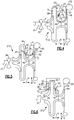
- FIG. 1 schematically illustrates a first example refrigerant system 10.
- the refrigerant system 10 includes a compressor 12.
- the compressor 12 is a centrifugal compressor including first and second impellers 14, 16, meaning the compressor 12 is a two-stage compressor.
- the first and second impellers 14, 16 are mounted along a shaft 18, which is rotationally driven by a motor 20.
- the speed of the motor 20 is adjustable to (at least partially) regulate the capacity of the compressor 12.
- the compressor 12 is configured to pressurize a flow of fluid, which is refrigerant in this example, within a refrigerant loop L.
- the system 10 Downstream of the compressor 12, the system 10 includes a condenser 22, which is upstream of first and second expansion valves 24, 26.
- the first expansion valve 24 is upstream of an economizer 28 and is controllable by a controller (not shown) to direct a first flow of fluid through the economizer 28.
- the first flow of fluid cools a second flow of fluid flowing through the economizer 28 toward the second expansion valve 26, which is downstream of the economizer 28.
- An evaporator 30 is positioned downstream of the second expansion valve 26 and upstream of the compressor 12.
- the compressor 12 is in fluid communication with an economizer flow path E, which is sourced from the refrigerant loop L at the economizer 28. Further, the compressor 12 is in fluid communication with a recirculation flow path R. In this example, the recirculation flow path R is sourced from the refrigerant loop L at a location downstream of the second impeller 16, such as an outlet (or exit) of the compressor 12.
- the economizer and recirculation flow paths E, R will be discussed in detail below.
- FIG. 2 illustrates another refrigerant system 110 according to this disclosure.
- the system 110 includes a compressor 12 configured to pressurize a flow of fluid within a refrigerant loop L. Downstream of the compressor 12, system 110 includes a condenser 22, which is upstream of first and second expansion valves 124, 126. Between the first and second expansion valves 124, 126, the system 110 includes an economizer 128, which in this example is an economizer tank (also known as a "flash" tank).
- economizer tank also known as a "flash" tank
- the first expansion valve 124 is upstream of the economizer 128, and the second expansion valve 126 is provided between the economizer 128 and an evaporator 30, which is upstream of the compressor 12.
- the compressor 12 is in fluid communication with an economizer flow path E, which is sourced from the refrigerant loop L at the economizer 128. Further, the compressor 12 is in fluid communication with a recirculation flow path R. Like the system 10, the recirculation flow path R is sourced from the refrigerant loop L at a location downstream of the second impeller 16.
- Figure 3 illustrates a system 210 that does not include an economizer.
- the system 210 there is a compressor 12, and a condenser 22 downstream of the compressor 12. Since there is no economizer, the system 210 only includes a single expansion valve 224 (such as the valves 26, 126), which is downstream of the condenser 22 and upstream of the evaporator 30.
- the system 210 includes a recirculation flow path R, which, like the prior-discussed examples, is sourced from a location downstream of the second impeller 16.
- FIGs 4-9 schematically illustrate six example compressors 112, 212, 312, 412, 512, and 612. Each of these compressors 112, 212, 312, 412, 512, and 612 may be used as the compressor 12 in any one of the systems 10, 110, 210 illustrated between Figures 1-3 .
- FIG 4 schematically illustrates a first example compressor 112.
- the compressor 12 includes an inlet, at 34, including controllable inlet guide vanes 36.
- the inlet guide vanes 36 are configured to control capacity of the compressor 112 by throttling a flow of fluid F 1 from the refrigerant loop L.
- the flow path of the fluid F 1 is referred to herein as the main flow path of the compressor 112.
- the compressor 112 does not include inlet guide vanes 36.
- the fluid F 1 enters the compressor 112 via the inlet 34, and flows axially (in the axial direction A) over the inlet guide vanes 36 and toward the first impeller 14.
- the first impeller 14 pressurizes the fluid F 1 , and radially expels (in the radial direction Z) the fluid F 1 downstream toward a first vaneless diffuser 38.
- a crossover bend 40 turns the fluid F 1 radially inward toward a return channel 42, which may include deswirl vanes.
- the compressor 112 includes a port 44 (which itself may be provided by a number of gas injection holes) provided adjacent the return channel 42.
- the port 44 is fluid communication with the economizer flow path E and the recirculation flow path R. Fluid from the economizer flow path E is illustrated at F 2 , and fluid from the recirculation flow path R is illustrated at F 3 .
- the recirculation fluid F 3 is controllable via the flow regulator 32 to selectively introduce the flow of fluid F 3 into the port 44.
- the flow regulator 32 is controlled via a controller (not pictured) to introduce the fluid F 3 into the fluid F 1 at select times.
- the flow regulator 32 is closed when the compressor 112 is operating at a normal capacity.
- a normal capacity range is about 40-100% of the designed capacity.
- the controller instructs the inlet guide vanes 36 to close and the flow regulator 32 to open, such that fluid F 3 flows to the port 44 via the recirculation flow path R. Additionally or alternatively, the controller may instruct the flow regulator 32 to open during compressor start-up in some examples.
- the combined flows of fluid F 1 -F 3 flow from the return channel 42 to the return channel exit 46. Then, the combined fluids F 1 -F 3 are pressurized by the second impeller 16, and are radially expelled toward a second vaneless diffuser 48. Finally, the combined fluids F 1 -F 3 flow to an outlet volute 50.
- the outlet volute 50 need not be in the form of a volute, however, and other types of outlets come within the scope of this disclosure.
- the recirculation flow path R is provided between the outlet volute 50 and the port 44, and, as mentioned, the flow regulator 32 selectively taps a portion of the fluid within the main flow path for recirculation.
- the recirculation flow path R could be sourced from another location, including any location downstream of the second impeller 14 and upstream of the condenser 22.
- the injection of fluid from the economizer flow path E and/or the recirculation flow path R increases the stability of operation of the compressor 112 in part-load conditions by allowing the downstream elements (e.g., the second impeller 16) to experience flows closer to their optimum range.
- Figure 5 illustrates a second example compressor 212.
- the compressor 212 includes a second port 52 downstream of the second impeller 16.
- the second port 52 is in fluid communication with the recirculation flow path R, and is arranged to inject the fluid F 3 adjacent the second vaneless diffuser 48.
- the economizer flow path E is in fluid communication with the port 44.
- injecting the fluids F 2 and F 3 via the ports 44 and 52 stabilizes the second stage impeller 16 during off-load conditions. Further, compared to Figure 4 , in which the fluid F 3 is injected via the port 44, injecting the fluid F 3 downstream of the second impeller 16 may have the benefit of improving overall compressor efficiency because there is no work that has been done to the fluid F 3 at that point (e.g., the fluid F3 was not pressurized by the second impeller 16 before being introduced into the main flow path).
- the compressors 112, 212 of Figures 4-5 provide a higher peak efficiency, albeit within a relatively narrow operating range. Unlike the compressors 112, 212 of Figures 4-5 , the compressors 312, 412, 512, and 612 of Figures 6-9 do not include inlet guide vanes 36. Instead, capacity is controlled by injecting fluid from the recirculation flow path R downstream of the first impeller 14, as discussed below.
- a flow of fluid F 1 is introduced to the inlet 34 from the refrigerant loop L.
- the flow of fluid F 1 is pressurized by the first impeller 14 and is radially expelled toward a first vaneless diffuser 38.
- the recirculation flow path R is sourced at the outlet volute 50.
- the arrangement of the recirculation flow path R in Figure 6 is the same as the arrangement of the recirculation flow path R described in co-pending U.S. Patent Application No. 14/096,395 , the entirety of which is herein incorporated by reference.
- the recirculation flow path R may be in communication with a recirculation volute and a plurality of injection nozzles, however this disclosure extends to other types of arrangements.
- the compressor 312 includes a first vaned diffuser 56, which includes a plurality of stationary (or, fixed) vanes, downstream of the first vaneless diffuser 38.
- the combined flows of fluid F 1 and F 3 flow radially through the first vaned diffuser 56 to a crossover bend 40, which radially turns the combined fluids F 1 , F 3 toward the return channel 42.
- the compressor 312 includes a port 44 adjacent the return channel 42.
- the port 44 is arranged to inject the fluid F 2 from the economizer flow path E into the compressor 312.
- the combined fluids F 1 -F 3 flow downstream to a second impeller 16 where they are pressurized and radially expelled.
- the compressor 312 Downstream of the second impeller 16, the compressor 312 includes a second vaneless diffuser 48 and a second vaned diffuser 58.
- the second vaned diffuser 58 is downstream of the second vaneless diffuser 48 and upstream of the outlet volute 50.
- the second vaned diffuser 58 includes stationary vanes.
- the injection of the fluid F 3 from the recirculation flow path R increases the stability of operation of the compressor 312 in part-load conditions by allowing the downstream elements (e.g., the first vaned diffuser 56, the second impeller 16, and the second vaned diffuser 58) to experience flows closer to their optimum range.
- the injection of the fluid F 2 further stabilizes the elements downstream of the port 44, namely the second impeller 16 and the second vaned diffuser 58.
- injecting the fluids F 2 , F 3 extends the efficient operating range of the compressor 312 to lower, part-load operating conditions, which reduces the likelihood of a surge condition.
- the compressor 312 does not require inlet guide vanes or variable geometry diffusers, which reduces the mechanical components within the compressor 312 and leads to increased reliability.
- Figure 7 illustrates a compressor 412 that is similar to the compressor 312 of Figure 6 , however the compressor 412 does not include a port (such as the port 44) adjacent the return channel 42. Instead, in the compressor 412, the fluid F 2 from the economizer flow path E and the fluid F 3 from the recirculation flow path R are each introduced into the compressor 412 via the port 54. This simplifies the construction of the compressor 412 by eliminating a port.
- Figures 6 and 7 include a first vaned diffuser 56 having stationary vanes
- other compressors such as the compressors 512, 612 of Figures 8 and 9
- the vanes of the variable geometry diffuser 60 are adjustable to control the capacity of the compressors 512, 612.
- the compressors 512, 612 can effectively control capacity without the need for inlet guide vanes.
- Figure 8 illustrates a first example compressor 512 including a variable geometry diffuser 60 downstream of the first impeller 14.
- the compressor 512 also includes a vaned diffuser 58 downstream of the second impeller 16.
- the flows of fluid F 2 , F 3 are injected into the compressor 12 via a port 44 adjacent the return channel 42, in substantially the same way as in the compressor 112 of Figure 4 .
- the capacity of the compressor 512 is effectively controlled by the variable geometry diffuser of the first impeller 14, while the injection of the fluids F 2 , F 3 via the port 44 stabilize the second impeller 16 as mentioned above relative to the compressor 112.
- Figure 9 illustrates a second example compressor 612 including a variable geometry diffuser 60 downstream of the first impeller 14.
- the compressor 612 includes a vaned diffuser 58 downstream of the second impeller 16. Similar to Figure 5 , the economizer flow path E is in fluid communication with the compressor 12 via the port 44, and the recirculation flow path R is in fluid communication with a second port 52 downstream of the second impeller 16.
- the flow of fluid F 2 from the economizer flow path E may be a consistent, steady flow, proportional to the capacity of the compressor.
- the compressors 212, 312, and 612 may exclude the port 44 (note that the compressors 112 and 512 inject the fluid F 3 via the port 44, and thus there is still a need for the port 44 even when the economizer flow path E is eliminated).
Landscapes
- Engineering & Computer Science (AREA)
- Mechanical Engineering (AREA)
- General Engineering & Computer Science (AREA)
- Physics & Mathematics (AREA)
- Thermal Sciences (AREA)
- Life Sciences & Earth Sciences (AREA)
- Sustainable Development (AREA)
- Structures Of Non-Positive Displacement Pumps (AREA)
- Control Of Positive-Displacement Air Blowers (AREA)
Claims (11)
- Zentrifugal-Kühlmittelverdichteranlage (10), die Folgendes umfasst:einen Kondensator (22),einen Verdampfer (30),einen Vorwärmer (28, 128) zwischen dem Kondensator (22) und dem Verdampfer (30),einen Zentrifugalverdichter (12), der ein erstes Laufrad (14) und ein zweites Laufrad (16) stromabwärts von dem ersten Laufrad (14) einschließt,einen Rückführungskanal (42) zwischen dem ersten und dem zweiten Laufrad (14, 16), undeine Vorwärmer-Strömungsbahn (E) zwischen dem Vorwärmer (28, 128) und dem Verdichter (12),wobei der Verdichter mindestens einen Anschluss (44) umfasst, der derart konfiguriert ist, dass Fluid aus einer Wiederumlauf-Strömungsbahn (R) und der Vorwärmer-Strömungsbahn (E) mit Hilfe des mindestens einen Anschlusses (44) in eine Hauptströmungsbahn (F1) des Verdichters eingeleitet wird,wobei die Wiederumlauf-Strömungsbahn (R) zwischen einem Auslass des Verdichters (50) und dem mindestens einen Anschluss (44) bereitgestellt wird,wobei der mindestens eine Anschluss ein einzelner Anschluss (44) ist, der stromabwärts von dem ersten Laufrad (14) und stromaufwärts von dem zweiten Laufrad (16) bereitgestellt wird, und wobei der Anschluss (44) angrenzend an den Rückführungskanal (42) bereitgestellt wird.
- Kühlmittelanlage nach Anspruch 1, wobei der Verdichter (12) eines von (1) einem Diffusor (60) mit veränderlicher Geometrie und (2) Einlass-Führungsschaufeln (36) einschließt.
- Kühlmittelanlage nach Anspruch 2, wobei der Verdichter (12) einen Diffusor (60) mit veränderlicher Geometrie stromabwärts von dem ersten Laufrad (14) einschließt und wobei der Verdichter (12) ferner einen unbeweglichen Schaufeldiffusor (58) stromabwärts von dem zweiten Laufrad (16) einschließt.
- Kühlmittelanlage nach Anspruch 2, wobei der Verdichter (112) Einlass-Führungsschaufeln (36) einschließt und wobei der Verdichter (12) ferner einen ersten und einen zweiten schaufellosen Diffusor (38, 48) jeweils stromabwärts von dem ersten beziehungsweise dem zweiten Laufrad (14, 16) einschließt.
- Kühlmittelanlage nach Anspruch 1, wobei der mindestens eine Anschluss (44) einen ersten Anschluss (44) und einen zweiten Anschluss (52) einschließt, wobei sich der erste Anschluss (44) stromabwärts von dem ersten Laufrad (14) und stromaufwärts von dem zweiten Laufrad (16) befindet und sich der zweite Anschluss (52) stromabwärts von dem zweiten Laufrad (16) und stromaufwärts von einem Auslass des Verdichters (50) befindet, wobei die Vorwärmer-Strömungsbahn (E) in Fluidverbindung mit dem ersten Anschluss (44) steht und wobei die Wiederumlauf-Strömungsbahn (R) in Fluidverbindung mit dem zweiten Anschluss (52) steht.
- Kühlmittelanlage nach Anspruch 5, wobei der Verdichter (12) eines von (1) einem Diffusor mit veränderlicher Geometrie (60) und (2) Einlass-Führungsschaufeln (36) einschließt.
- Kühlmittelanlage nach Anspruch 6, wobei der Verdichter einen Diffusor mit veränderlicher Geometrie (60) stromabwärts von dem ersten Laufrad (14) einschließt und wobei der Verdichter ferner einen unbeweglichen Schaufeldiffusor (58) stromabwärts von dem zweiten Laufrad (16) einschließt, wobei der zweite Anschluss (52) dem unbeweglichen Schaufeldiffusor (58) benachbart ist.
- Kühlmittelanlage nach Anspruch 6, wobei der Verdichter (12) Einlass-Führungsschaufeln (36) einschließt und wobei der Verdichter (12) ferner einen ersten und einen zweiten schaufellosen Diffusor (38, 48) jeweils stromabwärts von dem ersten beziehungsweise dem zweiten Laufrad (14, 16) einschließt.
- Kühlmittelanlage nach Anspruch 1, wobei der Verdichter ferner einen unbeweglichen Schaufeldiffusor (56) stromabwärts von dem ersten Laufrad (14) einschließt und wobei der mindestens eine Anschluss (44) einen ersten Anschluss (44) und einen zweiten Anschluss (52) einschließt, wobei der erste Anschluss (44) dem unbeweglichen Schaufeldiffusor (56) benachbart ist und sich der zweite Anschluss (52) stromabwärts von dem ersten Laufrad (14) und stromaufwärts von dem zweiten Laufrad (16) befindet, wobei die Wiederumlauf-Strömungsbahn (R) in Fluidverbindung mit dem ersten Anschluss (44) steht und wobei die Vorwärmer-Strömungsbahn (E) in Fluidverbindung mit dem zweiten Anschluss (52) steht.
- Kühlmittelanlage nach Anspruch 1, wobei der Verdichter ferner einen unbeweglichen Schaufeldiffusor (56) stromabwärts von dem ersten Laufrad (14) einschließt und wobei der einzelne Anschluss (44) dem unbeweglichen Schaufeldiffusor (56) benachbart ist.
- Kühlmittelanlage nach Anspruch 1, wobei der Auslass (50) des Verdichters durch ein Spiralgehäuse (50) bereitgestellt wird.
Applications Claiming Priority (2)
| Application Number | Priority Date | Filing Date | Title |
|---|---|---|---|
| US201361904160P | 2013-11-14 | 2013-11-14 | |
| PCT/US2014/065722 WO2015073835A1 (en) | 2013-11-14 | 2014-11-14 | Two-stage centrifugal compressor with extended range and capacity control features |
Publications (3)
| Publication Number | Publication Date |
|---|---|
| EP3069089A1 EP3069089A1 (de) | 2016-09-21 |
| EP3069089A4 EP3069089A4 (de) | 2017-11-01 |
| EP3069089B1 true EP3069089B1 (de) | 2020-08-05 |
Family
ID=53042483
Family Applications (1)
| Application Number | Title | Priority Date | Filing Date |
|---|---|---|---|
| EP14861633.7A Active EP3069089B1 (de) | 2013-11-14 | 2014-11-14 | Kältesystem mit zentrifugalverdichter |
Country Status (6)
| Country | Link |
|---|---|
| US (1) | US9382911B2 (de) |
| EP (1) | EP3069089B1 (de) |
| JP (1) | JP2016539311A (de) |
| KR (1) | KR102254251B1 (de) |
| CN (1) | CN105765319B (de) |
| WO (1) | WO2015073835A1 (de) |
Families Citing this family (25)
| Publication number | Priority date | Publication date | Assignee | Title |
|---|---|---|---|---|
| CN105240320B (zh) * | 2015-10-15 | 2019-01-22 | 珠海格力电器股份有限公司 | 一种离心式压缩机补气结构及压缩机 |
| US10563673B2 (en) | 2016-01-12 | 2020-02-18 | Daikin Applied Americas Inc. | Centrifugal compressor with liquid injection |
| WO2017135949A1 (en) * | 2016-02-04 | 2017-08-10 | Danfoss A/S | Active surge control in centrifugal compressors using microjet injection |
| EP3504440A4 (de) * | 2016-08-25 | 2020-04-01 | Danfoss A/S | Kühlkompressor |
| CN107013497B (zh) * | 2017-05-11 | 2024-03-19 | 珠海格力电器股份有限公司 | 回流器叶片、压缩机结构和压缩机 |
| US11156231B2 (en) * | 2018-03-23 | 2021-10-26 | Honeywell International Inc. | Multistage compressor having interstage refrigerant path split between first portion flowing to end of shaft and second portion following around thrust bearing disc |
| CN110360130B (zh) * | 2018-04-09 | 2022-12-27 | 开利公司 | 可变扩压器驱动系统 |
| US20200109879A1 (en) * | 2018-10-03 | 2020-04-09 | Danfoss A/S | Hvac compressor with mixed and radial compression stages |
| US11143193B2 (en) * | 2019-01-02 | 2021-10-12 | Danfoss A/S | Unloading device for HVAC compressor with mixed and radial compression stages |
| US11085684B2 (en) | 2019-06-27 | 2021-08-10 | Trane International Inc. | System and method for unloading a multi-stage compressor |
| EP3997343B1 (de) * | 2019-07-01 | 2023-08-09 | Carrier Corporation | Pumpschutz für einen mehrstufigen verdichter |
| JP2022545374A (ja) * | 2019-08-12 | 2022-10-27 | ジョンソン・コントロールズ・タイコ・アイピー・ホールディングス・エルエルピー | 最適化された段間流入口を有する圧縮機 |
| US11255338B2 (en) * | 2019-10-07 | 2022-02-22 | Elliott Company | Methods and mechanisms for surge avoidance in multi-stage centrifugal compressors |
| CN111255706A (zh) * | 2020-03-13 | 2020-06-09 | 珠海格力电器股份有限公司 | 离心压缩机 |
| US11536277B2 (en) | 2020-04-30 | 2022-12-27 | Trane International Inc. | Interstage capacity control valve with side stream flow distribution and flow regulation for multi-stage centrifugal compressors |
| US11391289B2 (en) | 2020-04-30 | 2022-07-19 | Trane International Inc. | Interstage capacity control valve with side stream flow distribution and flow regulation for multi-stage centrifugal compressors |
| TW202212694A (zh) * | 2020-07-30 | 2022-04-01 | 美商江森自控泰科知識產權控股有限責任合夥公司 | 用於引導壓縮機中的流體流之系統及方法 |
| JP2022186266A (ja) * | 2021-06-04 | 2022-12-15 | 三菱重工コンプレッサ株式会社 | 遠心圧縮機 |
| JP2024524949A (ja) * | 2021-06-16 | 2024-07-09 | コロラド ステート ユニバーシティー リサーチ ファウンデーション | 産業用蒸気発生のための空気源ヒートポンプシステムおよびその使用方法 |
| EP4733597A2 (de) * | 2021-11-03 | 2026-04-29 | Trane International Inc. | Zwischenstufen-kapazitätsregelventil mit seitenstromverteilung und durchflussregelung für mehrstufige zentrifugalverdichter |
| US11841026B2 (en) | 2021-11-03 | 2023-12-12 | Trane International Inc. | Compressor interstage throttle, and method of operating therof |
| US11946678B2 (en) | 2022-01-27 | 2024-04-02 | Copeland Lp | System and method for extending the operating range of a dynamic compressor |
| US20240253426A1 (en) * | 2023-01-27 | 2024-08-01 | Ford Global Technologies, Llc | Dehumidification control strategy |
| CN120548415A (zh) * | 2023-02-16 | 2025-08-26 | 株式会社Ihi | 压缩机 |
| CN121594004A (zh) * | 2024-08-20 | 2026-03-03 | 开利公司 | 离心压缩机、制冷热泵机组 |
Family Cites Families (43)
| Publication number | Priority date | Publication date | Assignee | Title |
|---|---|---|---|---|
| US2656096A (en) * | 1946-01-04 | 1953-10-20 | Rateau Soc | Centrifugal pump and compressor |
| DE842893C (de) | 1950-09-13 | 1952-07-03 | Siemens Ag | Selbstansaugende Kreiselpumpe |
| US3901620A (en) | 1973-10-23 | 1975-08-26 | Howell Instruments | Method and apparatus for compressor surge control |
| US4094613A (en) | 1976-05-07 | 1978-06-13 | Sundstrand Corporation | Variable output centrifugal pump |
| US4695224A (en) | 1982-01-04 | 1987-09-22 | General Electric Company | Centrifugal compressor with injection of a vaporizable liquid |
| JP2637144B2 (ja) * | 1988-03-08 | 1997-08-06 | 株式会社日立製作所 | 遠心圧縮機のサージング防止方法及び同装置 |
| IL109967A (en) | 1993-06-15 | 1997-07-13 | Multistack Int Ltd | Compressor |
| JPH08284892A (ja) * | 1995-04-10 | 1996-10-29 | Mitsubishi Heavy Ind Ltd | 遠心圧縮機のディフューザ |
| US5669756A (en) | 1996-06-07 | 1997-09-23 | Carrier Corporation | Recirculating diffuser |
| US6036432A (en) | 1998-07-09 | 2000-03-14 | Carrier Corporation | Method and apparatus for protecting centrifugal compressors from rotating stall vibrations |
| US6129511A (en) * | 1998-10-27 | 2000-10-10 | Carrier Corporation | Method and apparatus for controlling interaction between variable guide vanes and variable diffuser of a centrifugal compressor |
| KR100288315B1 (ko) * | 1999-03-15 | 2001-04-16 | 김평길 | 2단 원심압축기 |
| CA2373905A1 (en) | 2002-02-28 | 2003-08-28 | Ronald David Conry | Twin centrifugal compressor |
| US6672826B2 (en) | 2002-04-05 | 2004-01-06 | Mafi-Trench Corporation | Compressor surge control apparatus |
| US6997686B2 (en) * | 2002-12-19 | 2006-02-14 | R & D Dynamics Corporation | Motor driven two-stage centrifugal air-conditioning compressor |
| US7326027B1 (en) | 2004-05-25 | 2008-02-05 | The United States Of America As Represented By The Administrator Of The National Aeronautics And Space Administration | Devices and methods of operation thereof for providing stable flow for centrifugal compressors |
| DE602004014541D1 (de) * | 2004-06-07 | 2008-07-31 | Honeywell Int Inc | Verdichter mit entstellbarer rückführung und verfahren |
| DE602004015337D1 (de) | 2004-06-07 | 2008-09-04 | Honeywell Int Inc | Verdichter mit rückführung und verfahren |
| US8122724B2 (en) | 2004-08-31 | 2012-02-28 | Honeywell International, Inc. | Compressor including an aerodynamically variable diffuser |
| US7353660B2 (en) * | 2004-09-13 | 2008-04-08 | Carrier Corporation | Multi-temperature cooling system with unloading |
| FI20050119L (fi) | 2005-02-02 | 2006-08-03 | Sulzer Pumpen Ag | Menetelmä ja laite kaasumaisen tai nestemäisen aineen syöttämiseksi väliaineen joukkoon |
| JP2006284034A (ja) * | 2005-03-31 | 2006-10-19 | Mitsubishi Heavy Ind Ltd | 空気調和装置およびその膨張弁制御方法 |
| US7871239B2 (en) | 2006-02-03 | 2011-01-18 | Dresser-Rand Company | Multi-segment compressor casing assembly |
| DE102007017825A1 (de) | 2007-04-16 | 2008-10-23 | Continental Automotive Gmbh | Verdichtergehäuse und Turbolader |
| JP2009024582A (ja) * | 2007-07-19 | 2009-02-05 | Ihi Corp | ガス圧縮装置及びガス圧縮装置の制御方法 |
| DE102007035966A1 (de) | 2007-07-30 | 2009-02-05 | Bosch Mahle Turbosystems Gmbh & Co. Kg | Radialverdichter für einen Turbolader |
| JP2009085027A (ja) | 2007-09-27 | 2009-04-23 | Fujitsu General Ltd | 2段圧縮ロータリ圧縮機 |
| AU2008313765B2 (en) | 2007-10-17 | 2011-04-28 | Shell Internationale Research Maatschappij B.V. | Method and apparatus for controlling a refrigerant compressor, and use thereof in a method of cooling a hydrocarbon stream |
| TWI437167B (zh) * | 2007-10-31 | 2014-05-11 | Johnson Controls Tech Co | 控制系統 |
| JP5056447B2 (ja) * | 2008-02-06 | 2012-10-24 | 株式会社Ihi | ターボ圧縮機及び冷凍機 |
| JP5109696B2 (ja) * | 2008-02-06 | 2012-12-26 | 株式会社Ihi | 冷凍機 |
| IT1396001B1 (it) | 2009-04-28 | 2012-11-09 | Nuovo Pignone Spa | Sistema di recupero dell'energia in un impianto per la compressione di gas |
| US9677788B2 (en) * | 2009-06-12 | 2017-06-13 | Carrier Corporation | Refrigerant system with multiple load modes |
| JP2011043130A (ja) * | 2009-08-24 | 2011-03-03 | Hitachi Appliances Inc | 遠心圧縮機及び冷凍装置 |
| IT1401663B1 (it) | 2010-08-31 | 2013-08-02 | Nuovo Pignone Spa | Dispositivo e metodo per rilevare una sovracorrente in un compressore e spostare un margine di sovracorrente. |
| WO2012060825A1 (en) | 2010-11-03 | 2012-05-10 | Danfoss Turbocor Compressors B.V. | Centrifugal compressor with fluid injector diffuser |
| GB201122142D0 (en) | 2011-12-21 | 2012-02-01 | Venus Systems Ltd | Centrifugal compressors |
| US10072663B2 (en) * | 2012-01-23 | 2018-09-11 | Danfoss A/S | Variable-speed multi-stage refrigerant centrifugal compressor with diffusers |
| GB2499217A (en) | 2012-02-08 | 2013-08-14 | Edwards Ltd | Vacuum pump with recirculation valve |
| US9145858B2 (en) | 2012-02-29 | 2015-09-29 | Ford Global Technologies, Llc | Intake system with an integrated charge air cooler |
| FR2987602B1 (fr) | 2012-03-02 | 2014-02-28 | Aircelle Sa | Nacelle de turbomoteur equipe d'un echangeur de chaleur |
| EP2639411B1 (de) | 2012-03-12 | 2014-12-10 | MTU Aero Engines GmbH | Gehäuse einer Stömungsmaschine mit einem Fluidleitsystem |
| DE102012204403A1 (de) | 2012-03-20 | 2013-09-26 | Man Diesel & Turbo Se | Radialverdichtereinheit |
-
2014
- 2014-09-08 US US14/479,964 patent/US9382911B2/en active Active
- 2014-11-14 EP EP14861633.7A patent/EP3069089B1/de active Active
- 2014-11-14 KR KR1020167009678A patent/KR102254251B1/ko active Active
- 2014-11-14 WO PCT/US2014/065722 patent/WO2015073835A1/en not_active Ceased
- 2014-11-14 CN CN201480062120.2A patent/CN105765319B/zh active Active
- 2014-11-14 JP JP2016554525A patent/JP2016539311A/ja active Pending
Non-Patent Citations (1)
| Title |
|---|
| None * |
Also Published As
| Publication number | Publication date |
|---|---|
| US9382911B2 (en) | 2016-07-05 |
| KR102254251B1 (ko) | 2021-05-21 |
| EP3069089A1 (de) | 2016-09-21 |
| JP2016539311A (ja) | 2016-12-15 |
| CN105765319A (zh) | 2016-07-13 |
| KR20160084837A (ko) | 2016-07-14 |
| EP3069089A4 (de) | 2017-11-01 |
| WO2015073835A1 (en) | 2015-05-21 |
| CN105765319B (zh) | 2018-06-05 |
| US20150128640A1 (en) | 2015-05-14 |
Similar Documents
| Publication | Publication Date | Title |
|---|---|---|
| EP3069089B1 (de) | Kältesystem mit zentrifugalverdichter | |
| EP2951440B1 (de) | Kreiselverdichter mit erweitertem arbeitsbereich | |
| EP2635772B1 (de) | Radialverdichter mit diffusor mit flüssigkeitsinjektor | |
| EP2655890B1 (de) | Drehzahlvariabler radialverdichter mit ölfreiem kältemittel und variabler diffusorgeometrie | |
| US9816733B2 (en) | Economizer injection assembly and method | |
| US10072663B2 (en) | Variable-speed multi-stage refrigerant centrifugal compressor with diffusers | |
| US11255338B2 (en) | Methods and mechanisms for surge avoidance in multi-stage centrifugal compressors | |
| US10962016B2 (en) | Active surge control in centrifugal compressors using microjet injection | |
| US11143193B2 (en) | Unloading device for HVAC compressor with mixed and radial compression stages | |
| WO2025212238A1 (en) | Economizer flow and inlet guide vane configurations for refrigerant compressor |
Legal Events
| Date | Code | Title | Description |
|---|---|---|---|
| PUAI | Public reference made under article 153(3) epc to a published international application that has entered the european phase |
Free format text: ORIGINAL CODE: 0009012 |
|
| 17P | Request for examination filed |
Effective date: 20160316 |
|
| AK | Designated contracting states |
Kind code of ref document: A1 Designated state(s): AL AT BE BG CH CY CZ DE DK EE ES FI FR GB GR HR HU IE IS IT LI LT LU LV MC MK MT NL NO PL PT RO RS SE SI SK SM TR |
|
| AX | Request for extension of the european patent |
Extension state: BA ME |
|
| DAX | Request for extension of the european patent (deleted) | ||
| A4 | Supplementary search report drawn up and despatched |
Effective date: 20170929 |
|
| RIC1 | Information provided on ipc code assigned before grant |
Ipc: F25B 1/04 20060101AFI20170925BHEP Ipc: F04D 23/00 20060101ALI20170925BHEP Ipc: F04D 17/12 20060101ALI20170925BHEP Ipc: F25B 1/00 20060101ALI20170925BHEP |
|
| STAA | Information on the status of an ep patent application or granted ep patent |
Free format text: STATUS: EXAMINATION IS IN PROGRESS |
|
| 17Q | First examination report despatched |
Effective date: 20200113 |
|
| GRAP | Despatch of communication of intention to grant a patent |
Free format text: ORIGINAL CODE: EPIDOSNIGR1 |
|
| STAA | Information on the status of an ep patent application or granted ep patent |
Free format text: STATUS: GRANT OF PATENT IS INTENDED |
|
| INTG | Intention to grant announced |
Effective date: 20200319 |
|
| GRAS | Grant fee paid |
Free format text: ORIGINAL CODE: EPIDOSNIGR3 |
|
| GRAA | (expected) grant |
Free format text: ORIGINAL CODE: 0009210 |
|
| STAA | Information on the status of an ep patent application or granted ep patent |
Free format text: STATUS: THE PATENT HAS BEEN GRANTED |
|
| AK | Designated contracting states |
Kind code of ref document: B1 Designated state(s): AL AT BE BG CH CY CZ DE DK EE ES FI FR GB GR HR HU IE IS IT LI LT LU LV MC MK MT NL NO PL PT RO RS SE SI SK SM TR |
|
| REG | Reference to a national code |
Ref country code: GB Ref legal event code: FG4D |
|
| REG | Reference to a national code |
Ref country code: CH Ref legal event code: EP |
|
| REG | Reference to a national code |
Ref country code: AT Ref legal event code: REF Ref document number: 1299273 Country of ref document: AT Kind code of ref document: T Effective date: 20200815 |
|
| REG | Reference to a national code |
Ref country code: DE Ref legal event code: R096 Ref document number: 602014068722 Country of ref document: DE |
|
| REG | Reference to a national code |
Ref country code: IE Ref legal event code: FG4D |
|
| REG | Reference to a national code |
Ref country code: LT Ref legal event code: MG4D |
|
| REG | Reference to a national code |
Ref country code: NL Ref legal event code: MP Effective date: 20200805 |
|
| REG | Reference to a national code |
Ref country code: AT Ref legal event code: MK05 Ref document number: 1299273 Country of ref document: AT Kind code of ref document: T Effective date: 20200805 |
|
| PG25 | Lapsed in a contracting state [announced via postgrant information from national office to epo] |
Ref country code: LT Free format text: LAPSE BECAUSE OF FAILURE TO SUBMIT A TRANSLATION OF THE DESCRIPTION OR TO PAY THE FEE WITHIN THE PRESCRIBED TIME-LIMIT Effective date: 20200805 Ref country code: FI Free format text: LAPSE BECAUSE OF FAILURE TO SUBMIT A TRANSLATION OF THE DESCRIPTION OR TO PAY THE FEE WITHIN THE PRESCRIBED TIME-LIMIT Effective date: 20200805 Ref country code: BG Free format text: LAPSE BECAUSE OF FAILURE TO SUBMIT A TRANSLATION OF THE DESCRIPTION OR TO PAY THE FEE WITHIN THE PRESCRIBED TIME-LIMIT Effective date: 20201105 Ref country code: SE Free format text: LAPSE BECAUSE OF FAILURE TO SUBMIT A TRANSLATION OF THE DESCRIPTION OR TO PAY THE FEE WITHIN THE PRESCRIBED TIME-LIMIT Effective date: 20200805 Ref country code: ES Free format text: LAPSE BECAUSE OF FAILURE TO SUBMIT A TRANSLATION OF THE DESCRIPTION OR TO PAY THE FEE WITHIN THE PRESCRIBED TIME-LIMIT Effective date: 20200805 Ref country code: HR Free format text: LAPSE BECAUSE OF FAILURE TO SUBMIT A TRANSLATION OF THE DESCRIPTION OR TO PAY THE FEE WITHIN THE PRESCRIBED TIME-LIMIT Effective date: 20200805 Ref country code: PT Free format text: LAPSE BECAUSE OF FAILURE TO SUBMIT A TRANSLATION OF THE DESCRIPTION OR TO PAY THE FEE WITHIN THE PRESCRIBED TIME-LIMIT Effective date: 20201207 Ref country code: NO Free format text: LAPSE BECAUSE OF FAILURE TO SUBMIT A TRANSLATION OF THE DESCRIPTION OR TO PAY THE FEE WITHIN THE PRESCRIBED TIME-LIMIT Effective date: 20201105 Ref country code: GR Free format text: LAPSE BECAUSE OF FAILURE TO SUBMIT A TRANSLATION OF THE DESCRIPTION OR TO PAY THE FEE WITHIN THE PRESCRIBED TIME-LIMIT Effective date: 20201106 Ref country code: AT Free format text: LAPSE BECAUSE OF FAILURE TO SUBMIT A TRANSLATION OF THE DESCRIPTION OR TO PAY THE FEE WITHIN THE PRESCRIBED TIME-LIMIT Effective date: 20200805 |
|
| PG25 | Lapsed in a contracting state [announced via postgrant information from national office to epo] |
Ref country code: PL Free format text: LAPSE BECAUSE OF FAILURE TO SUBMIT A TRANSLATION OF THE DESCRIPTION OR TO PAY THE FEE WITHIN THE PRESCRIBED TIME-LIMIT Effective date: 20200805 Ref country code: NL Free format text: LAPSE BECAUSE OF FAILURE TO SUBMIT A TRANSLATION OF THE DESCRIPTION OR TO PAY THE FEE WITHIN THE PRESCRIBED TIME-LIMIT Effective date: 20200805 Ref country code: RS Free format text: LAPSE BECAUSE OF FAILURE TO SUBMIT A TRANSLATION OF THE DESCRIPTION OR TO PAY THE FEE WITHIN THE PRESCRIBED TIME-LIMIT Effective date: 20200805 Ref country code: LV Free format text: LAPSE BECAUSE OF FAILURE TO SUBMIT A TRANSLATION OF THE DESCRIPTION OR TO PAY THE FEE WITHIN THE PRESCRIBED TIME-LIMIT Effective date: 20200805 Ref country code: IS Free format text: LAPSE BECAUSE OF FAILURE TO SUBMIT A TRANSLATION OF THE DESCRIPTION OR TO PAY THE FEE WITHIN THE PRESCRIBED TIME-LIMIT Effective date: 20201205 |
|
| PG25 | Lapsed in a contracting state [announced via postgrant information from national office to epo] |
Ref country code: DK Free format text: LAPSE BECAUSE OF FAILURE TO SUBMIT A TRANSLATION OF THE DESCRIPTION OR TO PAY THE FEE WITHIN THE PRESCRIBED TIME-LIMIT Effective date: 20200805 Ref country code: CZ Free format text: LAPSE BECAUSE OF FAILURE TO SUBMIT A TRANSLATION OF THE DESCRIPTION OR TO PAY THE FEE WITHIN THE PRESCRIBED TIME-LIMIT Effective date: 20200805 Ref country code: EE Free format text: LAPSE BECAUSE OF FAILURE TO SUBMIT A TRANSLATION OF THE DESCRIPTION OR TO PAY THE FEE WITHIN THE PRESCRIBED TIME-LIMIT Effective date: 20200805 Ref country code: RO Free format text: LAPSE BECAUSE OF FAILURE TO SUBMIT A TRANSLATION OF THE DESCRIPTION OR TO PAY THE FEE WITHIN THE PRESCRIBED TIME-LIMIT Effective date: 20200805 Ref country code: SM Free format text: LAPSE BECAUSE OF FAILURE TO SUBMIT A TRANSLATION OF THE DESCRIPTION OR TO PAY THE FEE WITHIN THE PRESCRIBED TIME-LIMIT Effective date: 20200805 |
|
| REG | Reference to a national code |
Ref country code: DE Ref legal event code: R097 Ref document number: 602014068722 Country of ref document: DE |
|
| PG25 | Lapsed in a contracting state [announced via postgrant information from national office to epo] |
Ref country code: AL Free format text: LAPSE BECAUSE OF FAILURE TO SUBMIT A TRANSLATION OF THE DESCRIPTION OR TO PAY THE FEE WITHIN THE PRESCRIBED TIME-LIMIT Effective date: 20200805 |
|
| PLBE | No opposition filed within time limit |
Free format text: ORIGINAL CODE: 0009261 |
|
| STAA | Information on the status of an ep patent application or granted ep patent |
Free format text: STATUS: NO OPPOSITION FILED WITHIN TIME LIMIT |
|
| PG25 | Lapsed in a contracting state [announced via postgrant information from national office to epo] |
Ref country code: MC Free format text: LAPSE BECAUSE OF FAILURE TO SUBMIT A TRANSLATION OF THE DESCRIPTION OR TO PAY THE FEE WITHIN THE PRESCRIBED TIME-LIMIT Effective date: 20200805 Ref country code: SK Free format text: LAPSE BECAUSE OF FAILURE TO SUBMIT A TRANSLATION OF THE DESCRIPTION OR TO PAY THE FEE WITHIN THE PRESCRIBED TIME-LIMIT Effective date: 20200805 |
|
| REG | Reference to a national code |
Ref country code: CH Ref legal event code: PL |
|
| 26N | No opposition filed |
Effective date: 20210507 |
|
| PG25 | Lapsed in a contracting state [announced via postgrant information from national office to epo] |
Ref country code: LU Free format text: LAPSE BECAUSE OF NON-PAYMENT OF DUE FEES Effective date: 20201114 Ref country code: IT Free format text: LAPSE BECAUSE OF FAILURE TO SUBMIT A TRANSLATION OF THE DESCRIPTION OR TO PAY THE FEE WITHIN THE PRESCRIBED TIME-LIMIT Effective date: 20200805 |
|
| REG | Reference to a national code |
Ref country code: BE Ref legal event code: MM Effective date: 20201130 |
|
| PG25 | Lapsed in a contracting state [announced via postgrant information from national office to epo] |
Ref country code: CH Free format text: LAPSE BECAUSE OF NON-PAYMENT OF DUE FEES Effective date: 20201130 Ref country code: LI Free format text: LAPSE BECAUSE OF NON-PAYMENT OF DUE FEES Effective date: 20201130 Ref country code: SI Free format text: LAPSE BECAUSE OF FAILURE TO SUBMIT A TRANSLATION OF THE DESCRIPTION OR TO PAY THE FEE WITHIN THE PRESCRIBED TIME-LIMIT Effective date: 20200805 |
|
| PG25 | Lapsed in a contracting state [announced via postgrant information from national office to epo] |
Ref country code: IE Free format text: LAPSE BECAUSE OF NON-PAYMENT OF DUE FEES Effective date: 20201114 |
|
| PG25 | Lapsed in a contracting state [announced via postgrant information from national office to epo] |
Ref country code: TR Free format text: LAPSE BECAUSE OF FAILURE TO SUBMIT A TRANSLATION OF THE DESCRIPTION OR TO PAY THE FEE WITHIN THE PRESCRIBED TIME-LIMIT Effective date: 20200805 Ref country code: MT Free format text: LAPSE BECAUSE OF FAILURE TO SUBMIT A TRANSLATION OF THE DESCRIPTION OR TO PAY THE FEE WITHIN THE PRESCRIBED TIME-LIMIT Effective date: 20200805 Ref country code: CY Free format text: LAPSE BECAUSE OF FAILURE TO SUBMIT A TRANSLATION OF THE DESCRIPTION OR TO PAY THE FEE WITHIN THE PRESCRIBED TIME-LIMIT Effective date: 20200805 |
|
| PG25 | Lapsed in a contracting state [announced via postgrant information from national office to epo] |
Ref country code: MK Free format text: LAPSE BECAUSE OF FAILURE TO SUBMIT A TRANSLATION OF THE DESCRIPTION OR TO PAY THE FEE WITHIN THE PRESCRIBED TIME-LIMIT Effective date: 20200805 |
|
| PG25 | Lapsed in a contracting state [announced via postgrant information from national office to epo] |
Ref country code: BE Free format text: LAPSE BECAUSE OF NON-PAYMENT OF DUE FEES Effective date: 20201130 |
|
| P01 | Opt-out of the competence of the unified patent court (upc) registered |
Effective date: 20230621 |
|
| PGFP | Annual fee paid to national office [announced via postgrant information from national office to epo] |
Ref country code: DE Payment date: 20251007 Year of fee payment: 12 |
|
| PGFP | Annual fee paid to national office [announced via postgrant information from national office to epo] |
Ref country code: GB Payment date: 20251016 Year of fee payment: 12 |
|
| PGFP | Annual fee paid to national office [announced via postgrant information from national office to epo] |
Ref country code: FR Payment date: 20251023 Year of fee payment: 12 |