EP3069599A1 - Presse à balles - Google Patents
Presse à balles Download PDFInfo
- Publication number
- EP3069599A1 EP3069599A1 EP16151060.7A EP16151060A EP3069599A1 EP 3069599 A1 EP3069599 A1 EP 3069599A1 EP 16151060 A EP16151060 A EP 16151060A EP 3069599 A1 EP3069599 A1 EP 3069599A1
- Authority
- EP
- European Patent Office
- Prior art keywords
- winder
- bale
- slope
- chassis
- former
- Prior art date
- Legal status (The legal status is an assumption and is not a legal conclusion. Google has not performed a legal analysis and makes no representation as to the accuracy of the status listed.)
- Granted
Links
Images

Classifications
-
- A—HUMAN NECESSITIES
- A01—AGRICULTURE; FORESTRY; ANIMAL HUSBANDRY; HUNTING; TRAPPING; FISHING
- A01F—PROCESSING OF HARVESTED PRODUCE; HAY OR STRAW PRESSES; DEVICES FOR STORING AGRICULTURAL OR HORTICULTURAL PRODUCE
- A01F15/00—Baling presses for straw, hay or the like
- A01F15/07—Rotobalers, i.e. machines for forming cylindrical bales by winding and pressing
- A01F15/071—Wrapping devices
-
- A—HUMAN NECESSITIES
- A01—AGRICULTURE; FORESTRY; ANIMAL HUSBANDRY; HUNTING; TRAPPING; FISHING
- A01F—PROCESSING OF HARVESTED PRODUCE; HAY OR STRAW PRESSES; DEVICES FOR STORING AGRICULTURAL OR HORTICULTURAL PRODUCE
- A01F15/00—Baling presses for straw, hay or the like
- A01F15/07—Rotobalers, i.e. machines for forming cylindrical bales by winding and pressing
- A01F15/071—Wrapping devices
- A01F2015/0735—Combined machines that include a press bale and a wrapping device in a further step, e.g. turning table, not in the same closed pressing chamber
-
- A—HUMAN NECESSITIES
- A01—AGRICULTURE; FORESTRY; ANIMAL HUSBANDRY; HUNTING; TRAPPING; FISHING
- A01F—PROCESSING OF HARVESTED PRODUCE; HAY OR STRAW PRESSES; DEVICES FOR STORING AGRICULTURAL OR HORTICULTURAL PRODUCE
- A01F15/00—Baling presses for straw, hay or the like
- A01F15/07—Rotobalers, i.e. machines for forming cylindrical bales by winding and pressing
- A01F15/071—Wrapping devices
- A01F2015/076—Wrapping device incorporating sensors
-
- A—HUMAN NECESSITIES
- A01—AGRICULTURE; FORESTRY; ANIMAL HUSBANDRY; HUNTING; TRAPPING; FISHING
- A01F—PROCESSING OF HARVESTED PRODUCE; HAY OR STRAW PRESSES; DEVICES FOR STORING AGRICULTURAL OR HORTICULTURAL PRODUCE
- A01F15/00—Baling presses for straw, hay or the like
- A01F15/08—Details
- A01F2015/0808—Balers incorporate an inclinometer
Definitions
- the present invention relates to a baler with a chassis for supporting on the ground, a collector for collecting crop from the ground, a bale former for forming the collected crop into bales, and a winder for wrapping the bale with a net, a film or the like.
- the bale former is regularly followed by a winder which wraps a finished formed bale with a net, a foil or other wrapping material such as a string or membrane or the like.
- a winder which wraps a finished formed bale with a net, a foil or other wrapping material such as a string or membrane or the like.
- Such winder may be arranged with the bale former together on a common machine frame or a chassis part, wherein the winder may be disposed at an ejection opening of the bale former to take over the harvested bales ejected from the bale forming chamber, optionally between the bale former and the winder Transfer conveyor can be provided for example with an ejection or transfer carriage and / or a conveyor belt.
- the baler is quite bulky and expensive in the longitudinal direction, since a transfer conveyor that promotes a finished shaped bale of the bale forming chamber to the changing table, must be made tiltable in order to compensate for an adjusting itself by the compensating movements of the changing table height difference can.
- the problem remains that a bale in oblique driving approximately along a contour line of a slope slipping on the changing table or can not be reliably passed to the winder, since only inclination in the direction of travel, ie gradients and gradients can be compensated.
- a round baler in which the bale former or its bale forming chamber can be adjusted in height relative to the ground.
- a kink drawbar is provided in conjunction with a clearly spaced from the chassis axle arrangement of the bale forming chamber, so that a bending of the articulated drawbar causes a height adjustment of the bale forming chamber.
- This height adjustment should be used to ensure a sufficient slope to the changing table when ejecting a bale and to avoid a collision of the hinged Ballenformhunt rear wall with the winder.
- the problems described above with regard to the bale transfer and the winding process with excessive slopes are not solved here.
- the present invention is therefore an object of the invention to provide an improved baling press of the type mentioned, avoids the disadvantages of the prior art and the latter develops in an advantageous manner.
- a trouble-free wrapping of the bale is to be made possible even with larger slopes, without having to sacrifice a compact, simple machine structure for this purpose.
- the baler is characterized by a Determining device for determining the slope and / or an inclination of the baler in the sense of an inclination to a target orientation in a riot on a horizontal bottom surface and a control device for controlling the working speed and / or acceleration of at least one working tool of the bale former and / or the winder and / or a between the winder and bale former provided transfer conveyor depending on the specific slope and / or inclination.
- control device can increase or decrease the maximum speed of the working tool or adapt the speed profile provided for an adjusting movement to the slope inclination, for example approaching more gently depending on the slope or braking more abruptly, for example, for the dropping action on the slope to adapt or to exert less accelerations on the bale during a starting movement and thus to reduce its tendency to roll away.
- control device can make the working speed and / or acceleration of the at least one working tool progressively slowed down / reduced with increasing slope. This can generally reduce the tendency to malfunction.
- certain work tools and / or work functions can increasingly increase the working speed and / or acceleration with increasing slope.
- the transfer conveyor can pass the bale at high speed on the changing table when driving downhill to ensure against the slope down force that the bale rolls properly on the changing table.
- winding elements of the winder by the control device with increasing slope across the direction of travel and / or increasing slope in the direction of travel are increasingly slowed down operable.
- a conveyor in particular conveyor slide and / or conveyor belt, the transfer conveyor of the control device with increasing slope in the direction of downhill increasingly faster and / or increasingly slowed down with increasing slope in the direction of travel are increasingly slowed down.
- Said conveying means in the form of a conveyor carriage and / or conveyor belt of the transfer conveyor can be increasingly slowed down by the control device even with increasing inclination transverse to the direction of travel operable.
- the position or working position füridest a functional aggregate of the baler can be varied depending on the slope or inclination of the machine to allow a more stable operation.
- a catch position of the conveying means of the transfer conveyor relative to the bale former and / or a discharge position of the conveying means of the transfer conveyor relative to the winder and / or a catching position of the wrapping table of the winder relative to the transfer conveyor and / or relative to the bale former is variably adjustable depending on the slope.
- the distance of the conveyor of the transfer conveyor from the bale former increasingly smaller and / or increases with increasing slope in the direction of travel uphill increasingly. This is based on the consideration that the bales deposited by the bale former are placed further forward or farther at higher slopes, so that keeping the conveyor carriage closer to the bale former or farther away results in the bale being placed exactly on the conveyor carriage becomes.
- the position of the winder, in particular the distance of the changing table of the bale former or transfer conveyor can be adapted to the slope.
- the distance of the winder from the bale former increasingly smaller and / or increased with increasing slope in the direction of travel uphill increasingly.
- the baler can also make a slope compensation of its functional units transverse to the direction of travel and / or in the direction of travel.
- a slope compensation device may comprise at least one bank angle actuator for tilting the bale former and / or the winder against a slope transverse to the direction of travel.
- said slope compensation device may also have at least one pitch actuator actuator for tilting the bale former and / or the winder about a horizontal pitch axis oriented transversely to the direction of travel.
- the slope compensation device can provide for joint tilting of the bale former and of the winder, so that at least no larger angular offset between the bale former and the winder results when tilt compensation. This further improves the transfer of a shaped bale from the bale former to the winder.
- a common storage of bale former and winder may be attached to a chassis member to which the bale former is also attached, such that the aforesaid bank and pitch actuators only need to tilt said common chassis member to provide tilt balancing of the bale former and winder.
- a tilt compensation transverse to the direction of travel or tilting of the bale former and / or the winder can be achieved transversely to the direction by means of a height-adjustable chassis, in which a right side of the chassis and / or a left side of the chassis independent of and / or in opposite directions can be adjusted in height to a different chassis side.
- a height-adjustable chassis in which a right side of the chassis and / or a left side of the chassis independent of and / or in opposite directions can be adjusted in height to a different chassis side.
- This may already be sufficient if only one landing gear side is designed to be height adjustable.
- both chassis sides can be designed to be height adjustable, in order to be able to make a tilt compensation regardless of the orientation of the slope without collision problems or with sufficient ground clearance.
- a bogey chassis in which two wheel axles can be combined in the manner of a twin axle and can be pivoted by means of pivotable axle carriers.
- pivotable axle carriers By swiveling apart and / or pivoting together of the wheel axles, the wheels are height-adjusted relative to the chassis part on which the axle carriers are articulated.
- the aforesaid bank angle actuator of the inclination compensating device may in this case be a pivoting actuator for pivoting said axle carrier and, for example, in the form of a pressure medium cylinder, may act on said pivotable axle carrier.
- the axle can be mounted on a common or two separate, lying transversely to the direction of travel pivot axes and by the pressure medium cylinder, which may have at each of the axle a spaced from the pivot axis, articulated pivot point connected to each other. This can be adjusted with a simple linear Stellaktor by retracting and extending the height of the bogey chassis.
- Such a height-adjustable undercarriage can be used here not only to equalize or reduce bank angles or to tilt the bale former and / or the winder transversely to the direction of travel, but can also serve to increase by gleichschreibes height adjustment of the right and left side of the chassis short-term ground clearance For example, when driving over hills or when driving through depressions.
- such a chassis height adjustment can also be used to n pitches of the bale former and / or the winder at uphill and / or to reduce downhill or downhill, especially in a design of the baler as an attachment that can be grown on a tiller or other attachment to a tractor. If the attachment point or the drawbar pivot point on the tractor is considered to be stable in height, a downward slope of the chassis and thus an elevation of the chassis can reduce a slope for uphill driving, while conversely for downhill driving a lowering of the chassis, ie a top-retracting the landing gear can be compensated for a corresponding slope.
- the height-adjustable chassis fulfills a dual function. By one-sided or opposite height adjustment of the chassis sides it causes a compensation of bank angles. By mutual height adjustment on both sides it compensates pitch inclines.
- a kink drawbar may be provided by means of which the bale former and / or the winder can be tilted about a lying, aligned transversely to the direction of travel pitch axis to compensate for slopes in uphill and downhill.
- the aforesaid pitch inclination actuator of the slope compensation device can in this case be a swivel actuator which pivots the articulated drawbar, for example in the form of a pressure medium cylinder.
- an at least partial compensation of slopes transverse to the direction of travel can also be achieved by tilting the bale former and / or the winder relative to a chassis member supported on the ground by at least one horizontal tilting axis pointing in the direction of travel is stored.
- a rigid or at least not height adjustable chassis can be used, by which a lower part of the machine frame or a lower chassis part is always guided parallel to the ground. Tilt compensation is achieved by tilting the bale former and / or the winder relative to this lower chassis member.
- the tilting of the bale former and / or the winder against the respective slope in order to achieve a horizontal orientation as possible can in principle be manually controlled or operated.
- a semi-automatic or fully automatic control of the slope compensation device can be provided.
- a control device which controls the slope compensation device depending on the operating state of the bale former and / or the winder, in particular such that the bale former and / or the winder is only temporarily tilted against the slope, if this is for a Bale transfer from Ballenformer to the winder and / or is necessary for a winding process.
- said control device may have an actuator for only temporary tilting of the bale former and / or the winder during a bale transfer from the bale former to the winder and / or during a bale wrapping operation.
- said actuator may deactivate the slope compensation means and / or not cause tilting and / or the bale former and / or winder hold a slope parallel alignment.
- the operator may operate the slope compensation device to tilt the bale former and winder against the slope to compensate to reach the slope.
- the tilting of the bale former and / or winder can be reversed again to impede the transfer of the crop from the collector to the bale former as little as possible.
- the bale former and / or the winder against the slope only in a relatively narrow time window to the bale transfer and / or the Wrapping tilted around and kept in the rest of their operating time in their untilted neutral position.
- the control device can also work continuously or always balance the slope that occurs and control the incline adjustment actuators not only in certain time windows during operation. If the control device also takes into account further operating parameters of the baling press beyond the signal of the inclination sensor, in particular one or more operating state parameters of the bale former or winder, this can also be carried out, for example, such that the control device determines the strength of the counterbending or the degree of inclination compensation to the operating state the baler adapts.
- a stronger tilt compensation may be provided when the winder is in operation and / or a bale is to be handed over and a weaker pitch compensation is provided when the winder is out of service and no bale is transferred and / or the bale former in operation is.
- the slope compensation device is actuated in this case taking into account the direction and / or strength of the slope.
- the said control means control the inclination actuators of the slope inclination compensation device in particular in such a way that as horizontal a possible orientation of the bale former and / or the winder is achieved.
- the aforementioned determination device for determining the slope can determine a deviation of the bale former and / or the winder against a horizontal orientation, for example with Help of a Lotpendels and / or a spirit level and / or an absolute tilt sensor.
- the said control means can the inclination Stellaktoren the slope compensation device so control that the particular deviation from the horizontal orientation is as small as possible.
- the aforementioned inclination sensor for detecting the inclination of the baler may basically be formed differently.
- the tilt sensor may comprise a ball arranged in a cup-shaped cage, the position of which is detected electronically in the cage shell, or comprise a spring mass system, in which the deflection of a small test mass is detected electronically as a function of the position.
- an electronic tilt sensor may be provided in an advantageous embodiment of the invention, which contains a dielectric fluid whose position or level can be detected capacitively or inductively in a receptacle.
- a tilt sensor has an extremely fast response and can reliably detect the inclination of the baler even in rough field operation.
- the at least one inclination sensor can be multi-axially working and / or multiple inclination sensors can be provided for multi-axis inclination detection in order to be able to detect the inclination of the machine room in space with respect to several axes.
- a transverse inclination of the machine structure to the right and left transversely to the direction of travel and a pitch inclination forward and rearward in the direction of travel in each case relative to a vertical can be detected.
- baler only provides uniaxial inclination compensation, in particular in a plane perpendicular to the direction of travel or tilting of the machine structure transversely to the direction of travel to the right and left.
- the uniaxial inclination sensor then becomes advantageously arranged such that an inclination of the machine frame is detected transversely to the direction of travel to the right and left.
- the at least one inclination sensor can in principle be attached to different positions of the baler, for example directly on the machine frame or an associated portion of the machine structure, wherein the inclination sensor can be advantageously housed inside a housing part to protect the sensor from external damage.
- the at least one inclination sensor can detect a deviation of the orientation of the machine frame relative to the vertical and / or with respect to a horizontal plane.
- the electronic control device controls the inclination adjusting actuators in the sense of a regulation such that the detected deviation approaches zero, i. E. the machine frame comes as possible in its desired orientation as on a horizontal field, as far as this allow predetermined Verkippungsskyn for the tilting of the machine frame relative to the chassis.
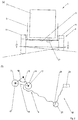
- the baler 1 may be designed as an attachment that can be attached to a not specifically shown tractor, for example by means of a drawbar 2, which is connected to a machine frame 3, which is supported by a chassis 4 on the ground.
- a collector 5 can be suspended for collecting crop from the ground, said collector 5 may be formed, for example in the form of a pickup with a circumferentially drivable spiked roller and a downstream conveyor rotor to crop such as hay, straw or grass from the ground pick up.
- the aforementioned pick-up 5 can be guided by a push-pull 6 over the ground and be pivotable relative to the machine frame 3.
- the collected by the collector 5 from the ground crop is transferred to a bale former 7, which may have a bale forming chamber 8 in a conventional manner in which by means of rotating belt and / or rotating rollers incoming crop can be formed into a bale.
- a bale former 7 which may have a bale forming chamber 8 in a conventional manner in which by means of rotating belt and / or rotating rollers incoming crop can be formed into a bale.
- Ballenformer 7 including its bale forming chamber 8 may be mounted on said machine frame 3.
- Subordinate to said bale former 7 is a winder 9, to which the bale former 7 can transfer a ready-formed bale.
- Said winder 9 can wrap the bale with a net, foil or other wrapping material before the wrapped bale is then placed on the ground.
- said winder 9 can have, for this purpose, in a manner known per se, a wrapping table 30 and wrapping elements 28 arranged here around, for example in the form of winding rolls, cf. Fig. 1 ,
- a transfer conveyor 27 may be provided with a Föderschlitten between the winder 9 and the bale former 7, which can be moved back and forth in the manner of a shuttle between the bale former 7 and the winder 9, to pass the bale accordingly.
- the named winder 9 can advantageously be mounted on the machine frame 3 by means of a winding device carrier 10, so that the winder 9 and the bale former 7 are mounted in common on the machine frame 3 or a chassis part of the machine frame 3.
- the winding device carrier 10 can be mounted on and telescoped or slidably mounted on the machine frame 3 in order to vary the distance of the winder 9 of the bale former 7, which mtels a controllable by the control device 20 Stellaktors can be done.
- the control device 20 adapts actuating movements of the work tools of the tilt-critical functional units to the occurring slope, as explained in detail above has been. Depending on the slope, the working tools of the bale former 7 and / or the transfer conveyor 27 and / or the winder 9 faster or slower process or more or less accelerated.
- the machine frame 3 with the bale shapers 7 and winder 9 mounted thereon can also be tilted relative to the ground contact surface defined by the wheels 11 of the chassis 4, which is accomplished by means of a slope compensation device 12, to counteract excessive slopes Act.
- a slope compensation device 12 to counteract excessive slopes Act.
- control device can adjust the actuating movements of the working tools of the tilt-critical functional units to the occurring slope, as was explained in detail above, when a counter-leaning of the functional aggregates contrary to the slope or the said tilt Ausgiesoch reaches its limits, for example, a maximum Jacobneigen was made, the winder and / or the bale former but still has a tendency.
- the machine frame 3 with the bale shapers 8 and winder 9 carried thereby can be tilted multiaxially, in particular about a tilt pitch axis 13, which extends transversely to the direction of travel, and about a bank tilt axis 14, which extends lying approximately in the direction of travel ,
- the said drawbar 2 may be formed as articulated drawbar, which can be bent over a lying, transverse to the direction of travel articulated dowel axis 15 relative to the machine frame 3, this by a Nickne Trentsstellaktor 16, for example in the form of an attacking on the articulated drawbar Pressure medium cylinder can be done.
- the chassis 4 can be adjusted in height relative to the machine frame 3, wherein a pitch about the pivot point of the drawbar 3 can be brought to the tractor by the same direction adjustment of the right and left halves.
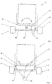
- the chassis 4 in this case may be formed as a biaxial bogey chassis, in which the wheel axles 17 of two paired wheels 11 are suspended from pivotable axle beams 18.
- the above-mentioned axle carriers 18 can advantageously be articulated pivotably about a common transverse axis on the machine frame 3 and pivoted relative to each other by a chassis actuator 19 so that the wheels 11 can be moved closer together and farther away from each other, thus increasing the height bearing of the wheels 11 relative to the machine frame 3 changes.
- the aforementioned axle carriers 18 can also be articulated on separate transverse axes lying on the machine frame 3.
- the right and left landing gear sides can be adjusted in height independently of each other and / or in opposite directions.
- the mentioned Fahrtechniksstellaktoren 19 the right and left sides of said bogey suspension are assigned to be independently controlled by the slope compensation device 12 and one of these associated control device 20 or operated independently, so that either a suspension side or both suspension sides lowered or can be raised, like this Fig. 2 (a) clarified.
- slopes can be compensated transversely to the direction of travel or at least reduced.
- the machine frame 3 and the elements arranged thereon bale former 8 and 9 winder are thereby counter to the slope, ie tilted in particular uphill and kept as horizontal as possible.
- the control device 20 of the slope compensation device 12 can receive a signal from a tilt determination device 21, which indicates the slope angle and / or the deviation of the machine frame orientation from a horizontal orientation. Depending on the particular inclination and / or the particular deviation from the horizontal orientation, the control device 20 may actuate the landing gear actuators 19 and / or the pitch steering pitch pitch actuator 16 to maintain the most horizontal orientation possible.
- control device 20 in this case take into account the operating state of the bale former 7 and / or the winder 9 and cause a tilting of the machine frame 3 counter to the slope only when a bale transfer is performed by the bale former 7 to the winder 9 or pending and a winding process on Winder 9 is performed, as explained above.
- a tiltable mounting of the machine frame 3 may be provided. More specifically, a chassis top 3o of the machine frame 3, to which the bale former 7 and the winder 9 are attached, can be tilted relative to a chassis bottom 3u of the machine frame 3 about a horizontal bank tilt axis 14 pointing in the direction of travel.
- the aforementioned transverse tilting axis 14 can in this case be fixedly attached to the two chassis parts 3o and 3u and extend in particular in a vertical longitudinal center plane of the baling press 1.
- a bank actuator 22 may tilt the chassis upper 3o and thus the bale former 7 and the winder 9 about the bank tilt axis 17, said bank actuator 22 being, for example, a pressure cylinder spaced from the tilt axis 14 between the chassis upper and lower banks. Parts is switched.
- the mentioned bank actuator 22 can be controlled by the aforementioned control device 20 in the manner described, to compensate for slopes occurring transverse to the direction of travel as much as possible when a bale transfer or a winding process is performed.
- the chassis top 3o may also be tilted about different bank tilt axes 14 transverse to the direction of travel, said plurality of bank tilt axes 14 may extend spaced from a vertical longitudinal center plane of the baler 1, for example at right and left edge portions of the machine frame 3
- the said transverse tilting axes 14 can advantageously be lifted by pivoting actuators 22 articulated thereon relative to the chassis lower part 3u, so that either tilting about the left tilting axis or about the right tilting axis can be performed.
- a slope given transverse to the direction of travel can equally be compensated or reduced.
- the advantage here is that there is no lowering of an upwardly directed machine frame side and therefore ground clearance problems are avoided.
Landscapes
- Life Sciences & Earth Sciences (AREA)
- Environmental Sciences (AREA)
- Storage Of Harvested Produce (AREA)
- Agricultural Machines (AREA)
Priority Applications (1)
| Application Number | Priority Date | Filing Date | Title |
|---|---|---|---|
| PL16151060T PL3069599T3 (pl) | 2015-03-20 | 2016-01-13 | Prasa rolująca |
Applications Claiming Priority (1)
| Application Number | Priority Date | Filing Date | Title |
|---|---|---|---|
| DE102015003700.5A DE102015003700A1 (de) | 2015-03-20 | 2015-03-20 | Ballenpresse |
Publications (2)
| Publication Number | Publication Date |
|---|---|
| EP3069599A1 true EP3069599A1 (fr) | 2016-09-21 |
| EP3069599B1 EP3069599B1 (fr) | 2018-03-07 |
Family
ID=55129649
Family Applications (1)
| Application Number | Title | Priority Date | Filing Date |
|---|---|---|---|
| EP16151060.7A Active EP3069599B1 (fr) | 2015-03-20 | 2016-01-13 | Presse à balles |
Country Status (3)
| Country | Link |
|---|---|
| EP (1) | EP3069599B1 (fr) |
| DE (1) | DE102015003700A1 (fr) |
| PL (1) | PL3069599T3 (fr) |
Citations (10)
| Publication number | Priority date | Publication date | Assignee | Title |
|---|---|---|---|---|
| GB1189705A (en) * | 1967-08-03 | 1970-04-29 | Automotive Prod Co Ltd | Improvements in or relating to Levelling Devices for Mobile Structures. |
| US4602800A (en) * | 1983-04-28 | 1986-07-29 | Haglinge Industri Ab | Tractor |
| DE29911916U1 (de) | 1999-07-13 | 1999-09-30 | Kohnle, Eugen, 73485 Unterschneidheim | Wickelvorrichtung und System zum Pressen und Wickeln von Ballen |
| EP1153538A2 (fr) * | 2000-05-13 | 2001-11-14 | New Holland Belgium N.V. | Méthode et appareil pour contrôler une combinaison de tracteur et presse à balles |
| EP1297734A1 (fr) * | 2001-09-27 | 2003-04-02 | Deere & Company | Machine de récolte avec une vitesse d'avance qui est dépendante de l'inclinaison |
| DE60224751T2 (de) * | 2001-06-11 | 2009-04-09 | Welger Maschinenfabrik Gmbh | Rundballenpresse für landwirtschaftliche Halmgüter |
| EP2090153A1 (fr) * | 2008-02-13 | 2009-08-19 | Usines CLAAS France S.A.S. | Roto-presse |
| EP2196082A1 (fr) * | 2008-12-10 | 2010-06-16 | Lely Patent N.V. | Presse à ballots ronds fonctionnant en continu |
| DE102013108246A1 (de) * | 2013-08-01 | 2015-02-05 | Usines Claas France S.A.S. | Landwirtschaftliche Rundballenpresse |
| DE102013108248A1 (de) | 2013-08-01 | 2015-02-05 | Hella Kgaa Hueck & Co. | Beleuchtungssystem, insbesondere für einen Kraftfahrzeugscheinwerfer mit einem Kühlkörper |
Family Cites Families (6)
| Publication number | Priority date | Publication date | Assignee | Title |
|---|---|---|---|---|
| DE1059698B (de) * | 1955-05-14 | 1959-06-18 | Fahr Ag Maschf | Maehdrescher |
| IT984994B (it) * | 1973-05-18 | 1974-11-20 | Bruni M | Dispositivo autolivellatore per grosse macchine agricole |
| ES2257130B1 (es) * | 2003-10-08 | 2007-07-16 | Angel Carlos Irujo Lopez | Sistema nivelador-compensador para maquinas cosechadoras y similares. |
| DE102008010733A1 (de) * | 2008-02-24 | 2009-09-03 | Viessmann Werke Gmbh & Co Kg | Fahrzeug |
| ATE514330T1 (de) * | 2008-07-31 | 2011-07-15 | Deere & Co | Ballenpresse und einwicklerkombination |
| DE102011122151B4 (de) * | 2011-12-22 | 2014-01-23 | Maschinenfabrik Bernard Krone Gmbh | Press-Wickelkombination |
-
2015
- 2015-03-20 DE DE102015003700.5A patent/DE102015003700A1/de not_active Withdrawn
-
2016
- 2016-01-13 EP EP16151060.7A patent/EP3069599B1/fr active Active
- 2016-01-13 PL PL16151060T patent/PL3069599T3/pl unknown
Patent Citations (10)
| Publication number | Priority date | Publication date | Assignee | Title |
|---|---|---|---|---|
| GB1189705A (en) * | 1967-08-03 | 1970-04-29 | Automotive Prod Co Ltd | Improvements in or relating to Levelling Devices for Mobile Structures. |
| US4602800A (en) * | 1983-04-28 | 1986-07-29 | Haglinge Industri Ab | Tractor |
| DE29911916U1 (de) | 1999-07-13 | 1999-09-30 | Kohnle, Eugen, 73485 Unterschneidheim | Wickelvorrichtung und System zum Pressen und Wickeln von Ballen |
| EP1153538A2 (fr) * | 2000-05-13 | 2001-11-14 | New Holland Belgium N.V. | Méthode et appareil pour contrôler une combinaison de tracteur et presse à balles |
| DE60224751T2 (de) * | 2001-06-11 | 2009-04-09 | Welger Maschinenfabrik Gmbh | Rundballenpresse für landwirtschaftliche Halmgüter |
| EP1297734A1 (fr) * | 2001-09-27 | 2003-04-02 | Deere & Company | Machine de récolte avec une vitesse d'avance qui est dépendante de l'inclinaison |
| EP2090153A1 (fr) * | 2008-02-13 | 2009-08-19 | Usines CLAAS France S.A.S. | Roto-presse |
| EP2196082A1 (fr) * | 2008-12-10 | 2010-06-16 | Lely Patent N.V. | Presse à ballots ronds fonctionnant en continu |
| DE102013108246A1 (de) * | 2013-08-01 | 2015-02-05 | Usines Claas France S.A.S. | Landwirtschaftliche Rundballenpresse |
| DE102013108248A1 (de) | 2013-08-01 | 2015-02-05 | Hella Kgaa Hueck & Co. | Beleuchtungssystem, insbesondere für einen Kraftfahrzeugscheinwerfer mit einem Kühlkörper |
Also Published As
| Publication number | Publication date |
|---|---|
| PL3069599T3 (pl) | 2018-09-28 |
| EP3069599B1 (fr) | 2018-03-07 |
| DE102015003700A1 (de) | 2016-09-22 |
Similar Documents
| Publication | Publication Date | Title |
|---|---|---|
| EP2397027B1 (fr) | Moissonneuse agricole | |
| EP0995351A1 (fr) | Dispositif de commande d'un appareil de transfert | |
| EP4147563A1 (fr) | Moissonneuse dotée d'une tête réglable en hauteur | |
| EP3069600B1 (fr) | Moissonneuse | |
| EP2564683B1 (fr) | Système de commande d'un dispositif de chargement | |
| EP2878190B1 (fr) | Presse à balles rondes agricole | |
| DE102005004508A1 (de) | Vorrichtung zur gleichmäßigen Beschickung von Arbeitsmaschinen | |
| EP3735817B1 (fr) | Canal d'alimentation de moissonneuse-batteuse pourvu d'un châssis de couplage pendulaire monté sur rouleaux ainsi que procédé de compensation transversale passive | |
| EP2119341A2 (fr) | Outil de récolte doté d'un ramasseur de récolte et d'une vis sans fin transversale | |
| EP3338534B1 (fr) | Presse à balles rondes | |
| EP3069598B1 (fr) | Presse à fourrage | |
| EP3069599B1 (fr) | Presse à balles | |
| EP1072727B1 (fr) | Véhicule et procédé pour nettoyer les surfaces | |
| US6033172A (en) | Bale turning apparatus | |
| DE102019006298B4 (de) | Aufnahmevorrichtung für eine landwirtschaftliche Arbeitsmaschine, landwirtschaftliche Arbeitsmaschine und Arbeitszug mit einer solchen landwirtschaftlichen Arbeitsmaschine | |
| EP3491908B1 (fr) | Moissonneuse et/ou machine de traitement du sol agricole | |
| DE102004031514B3 (de) | Querpendeleinrichtung für Vorsatzgeräte an Landmaschinen | |
| DE102015006221A1 (de) | Erntemaschine | |
| EP4245121B1 (fr) | Dispositif pour basculer le déchargement de balles rondes | |
| EP3058804B1 (fr) | Faneuse | |
| EP4410088A1 (fr) | Moissonneuse agricole automotrice | |
| BE1026568B1 (de) | Selbstfahrende erntemaschine mit einer überladeeinrichtung | |
| EP1266556A2 (fr) | Machine à récolter des pommes de terre | |
| DE10116180C2 (de) | Kartoffelerntemaschine | |
| EP1872644B1 (fr) | Procédé et dispositif de commande d'un dispositif de ramassage de récolte |
Legal Events
| Date | Code | Title | Description |
|---|---|---|---|
| PUAI | Public reference made under article 153(3) epc to a published international application that has entered the european phase |
Free format text: ORIGINAL CODE: 0009012 |
|
| AK | Designated contracting states |
Kind code of ref document: A1 Designated state(s): AL AT BE BG CH CY CZ DE DK EE ES FI FR GB GR HR HU IE IS IT LI LT LU LV MC MK MT NL NO PL PT RO RS SE SI SK SM TR |
|
| AX | Request for extension of the european patent |
Extension state: BA ME |
|
| STAA | Information on the status of an ep patent application or granted ep patent |
Free format text: STATUS: REQUEST FOR EXAMINATION WAS MADE |
|
| 17P | Request for examination filed |
Effective date: 20170321 |
|
| RBV | Designated contracting states (corrected) |
Designated state(s): AL AT BE BG CH CY CZ DE DK EE ES FI FR GB GR HR HU IE IS IT LI LT LU LV MC MK MT NL NO PL PT RO RS SE SI SK SM TR |
|
| GRAP | Despatch of communication of intention to grant a patent |
Free format text: ORIGINAL CODE: EPIDOSNIGR1 |
|
| STAA | Information on the status of an ep patent application or granted ep patent |
Free format text: STATUS: GRANT OF PATENT IS INTENDED |
|
| INTG | Intention to grant announced |
Effective date: 20170810 |
|
| GRAS | Grant fee paid |
Free format text: ORIGINAL CODE: EPIDOSNIGR3 |
|
| GRAA | (expected) grant |
Free format text: ORIGINAL CODE: 0009210 |
|
| STAA | Information on the status of an ep patent application or granted ep patent |
Free format text: STATUS: THE PATENT HAS BEEN GRANTED |
|
| AK | Designated contracting states |
Kind code of ref document: B1 Designated state(s): AL AT BE BG CH CY CZ DE DK EE ES FI FR GB GR HR HU IE IS IT LI LT LU LV MC MK MT NL NO PL PT RO RS SE SI SK SM TR |
|
| REG | Reference to a national code |
Ref country code: GB Ref legal event code: FG4D Free format text: NOT ENGLISH |
|
| REG | Reference to a national code |
Ref country code: CH Ref legal event code: EP Ref country code: AT Ref legal event code: REF Ref document number: 975524 Country of ref document: AT Kind code of ref document: T Effective date: 20180315 |
|
| REG | Reference to a national code |
Ref country code: IE Ref legal event code: FG4D Free format text: LANGUAGE OF EP DOCUMENT: GERMAN |
|
| REG | Reference to a national code |
Ref country code: DE Ref legal event code: R096 Ref document number: 502016000620 Country of ref document: DE |
|
| REG | Reference to a national code |
Ref country code: NL Ref legal event code: FP |
|
| REG | Reference to a national code |
Ref country code: LT Ref legal event code: MG4D |
|
| PG25 | Lapsed in a contracting state [announced via postgrant information from national office to epo] |
Ref country code: HR Free format text: LAPSE BECAUSE OF FAILURE TO SUBMIT A TRANSLATION OF THE DESCRIPTION OR TO PAY THE FEE WITHIN THE PRESCRIBED TIME-LIMIT Effective date: 20180307 Ref country code: NO Free format text: LAPSE BECAUSE OF FAILURE TO SUBMIT A TRANSLATION OF THE DESCRIPTION OR TO PAY THE FEE WITHIN THE PRESCRIBED TIME-LIMIT Effective date: 20180607 Ref country code: FI Free format text: LAPSE BECAUSE OF FAILURE TO SUBMIT A TRANSLATION OF THE DESCRIPTION OR TO PAY THE FEE WITHIN THE PRESCRIBED TIME-LIMIT Effective date: 20180307 Ref country code: LT Free format text: LAPSE BECAUSE OF FAILURE TO SUBMIT A TRANSLATION OF THE DESCRIPTION OR TO PAY THE FEE WITHIN THE PRESCRIBED TIME-LIMIT Effective date: 20180307 Ref country code: CY Free format text: LAPSE BECAUSE OF FAILURE TO SUBMIT A TRANSLATION OF THE DESCRIPTION OR TO PAY THE FEE WITHIN THE PRESCRIBED TIME-LIMIT Effective date: 20180307 Ref country code: ES Free format text: LAPSE BECAUSE OF FAILURE TO SUBMIT A TRANSLATION OF THE DESCRIPTION OR TO PAY THE FEE WITHIN THE PRESCRIBED TIME-LIMIT Effective date: 20180307 |
|
| PG25 | Lapsed in a contracting state [announced via postgrant information from national office to epo] |
Ref country code: LV Free format text: LAPSE BECAUSE OF FAILURE TO SUBMIT A TRANSLATION OF THE DESCRIPTION OR TO PAY THE FEE WITHIN THE PRESCRIBED TIME-LIMIT Effective date: 20180307 Ref country code: RS Free format text: LAPSE BECAUSE OF FAILURE TO SUBMIT A TRANSLATION OF THE DESCRIPTION OR TO PAY THE FEE WITHIN THE PRESCRIBED TIME-LIMIT Effective date: 20180307 Ref country code: SE Free format text: LAPSE BECAUSE OF FAILURE TO SUBMIT A TRANSLATION OF THE DESCRIPTION OR TO PAY THE FEE WITHIN THE PRESCRIBED TIME-LIMIT Effective date: 20180307 Ref country code: BG Free format text: LAPSE BECAUSE OF FAILURE TO SUBMIT A TRANSLATION OF THE DESCRIPTION OR TO PAY THE FEE WITHIN THE PRESCRIBED TIME-LIMIT Effective date: 20180607 Ref country code: GR Free format text: LAPSE BECAUSE OF FAILURE TO SUBMIT A TRANSLATION OF THE DESCRIPTION OR TO PAY THE FEE WITHIN THE PRESCRIBED TIME-LIMIT Effective date: 20180608 |
|
| PG25 | Lapsed in a contracting state [announced via postgrant information from national office to epo] |
Ref country code: MT Free format text: LAPSE BECAUSE OF FAILURE TO SUBMIT A TRANSLATION OF THE DESCRIPTION OR TO PAY THE FEE WITHIN THE PRESCRIBED TIME-LIMIT Effective date: 20180307 |
|
| PG25 | Lapsed in a contracting state [announced via postgrant information from national office to epo] |
Ref country code: AL Free format text: LAPSE BECAUSE OF FAILURE TO SUBMIT A TRANSLATION OF THE DESCRIPTION OR TO PAY THE FEE WITHIN THE PRESCRIBED TIME-LIMIT Effective date: 20180307 Ref country code: RO Free format text: LAPSE BECAUSE OF FAILURE TO SUBMIT A TRANSLATION OF THE DESCRIPTION OR TO PAY THE FEE WITHIN THE PRESCRIBED TIME-LIMIT Effective date: 20180307 Ref country code: EE Free format text: LAPSE BECAUSE OF FAILURE TO SUBMIT A TRANSLATION OF THE DESCRIPTION OR TO PAY THE FEE WITHIN THE PRESCRIBED TIME-LIMIT Effective date: 20180307 |
|
| PG25 | Lapsed in a contracting state [announced via postgrant information from national office to epo] |
Ref country code: SM Free format text: LAPSE BECAUSE OF FAILURE TO SUBMIT A TRANSLATION OF THE DESCRIPTION OR TO PAY THE FEE WITHIN THE PRESCRIBED TIME-LIMIT Effective date: 20180307 Ref country code: SK Free format text: LAPSE BECAUSE OF FAILURE TO SUBMIT A TRANSLATION OF THE DESCRIPTION OR TO PAY THE FEE WITHIN THE PRESCRIBED TIME-LIMIT Effective date: 20180307 Ref country code: CZ Free format text: LAPSE BECAUSE OF FAILURE TO SUBMIT A TRANSLATION OF THE DESCRIPTION OR TO PAY THE FEE WITHIN THE PRESCRIBED TIME-LIMIT Effective date: 20180307 |
|
| REG | Reference to a national code |
Ref country code: DE Ref legal event code: R097 Ref document number: 502016000620 Country of ref document: DE |
|
| PG25 | Lapsed in a contracting state [announced via postgrant information from national office to epo] |
Ref country code: PT Free format text: LAPSE BECAUSE OF FAILURE TO SUBMIT A TRANSLATION OF THE DESCRIPTION OR TO PAY THE FEE WITHIN THE PRESCRIBED TIME-LIMIT Effective date: 20180709 |
|
| PLBE | No opposition filed within time limit |
Free format text: ORIGINAL CODE: 0009261 |
|
| STAA | Information on the status of an ep patent application or granted ep patent |
Free format text: STATUS: NO OPPOSITION FILED WITHIN TIME LIMIT |
|
| PG25 | Lapsed in a contracting state [announced via postgrant information from national office to epo] |
Ref country code: DK Free format text: LAPSE BECAUSE OF FAILURE TO SUBMIT A TRANSLATION OF THE DESCRIPTION OR TO PAY THE FEE WITHIN THE PRESCRIBED TIME-LIMIT Effective date: 20180307 |
|
| 26N | No opposition filed |
Effective date: 20181210 |
|
| PG25 | Lapsed in a contracting state [announced via postgrant information from national office to epo] |
Ref country code: SI Free format text: LAPSE BECAUSE OF FAILURE TO SUBMIT A TRANSLATION OF THE DESCRIPTION OR TO PAY THE FEE WITHIN THE PRESCRIBED TIME-LIMIT Effective date: 20180307 |
|
| PG25 | Lapsed in a contracting state [announced via postgrant information from national office to epo] |
Ref country code: MC Free format text: LAPSE BECAUSE OF FAILURE TO SUBMIT A TRANSLATION OF THE DESCRIPTION OR TO PAY THE FEE WITHIN THE PRESCRIBED TIME-LIMIT Effective date: 20180307 |
|
| REG | Reference to a national code |
Ref country code: CH Ref legal event code: PL |
|
| PG25 | Lapsed in a contracting state [announced via postgrant information from national office to epo] |
Ref country code: LU Free format text: LAPSE BECAUSE OF NON-PAYMENT OF DUE FEES Effective date: 20190113 |
|
| REG | Reference to a national code |
Ref country code: BE Ref legal event code: MM Effective date: 20190131 |
|
| PG25 | Lapsed in a contracting state [announced via postgrant information from national office to epo] |
Ref country code: BE Free format text: LAPSE BECAUSE OF NON-PAYMENT OF DUE FEES Effective date: 20190131 |
|
| PG25 | Lapsed in a contracting state [announced via postgrant information from national office to epo] |
Ref country code: LI Free format text: LAPSE BECAUSE OF NON-PAYMENT OF DUE FEES Effective date: 20190131 Ref country code: CH Free format text: LAPSE BECAUSE OF NON-PAYMENT OF DUE FEES Effective date: 20190131 |
|
| PG25 | Lapsed in a contracting state [announced via postgrant information from national office to epo] |
Ref country code: TR Free format text: LAPSE BECAUSE OF FAILURE TO SUBMIT A TRANSLATION OF THE DESCRIPTION OR TO PAY THE FEE WITHIN THE PRESCRIBED TIME-LIMIT Effective date: 20180307 |
|
| GBPC | Gb: european patent ceased through non-payment of renewal fee |
Effective date: 20200113 |
|
| PG25 | Lapsed in a contracting state [announced via postgrant information from national office to epo] |
Ref country code: GB Free format text: LAPSE BECAUSE OF NON-PAYMENT OF DUE FEES Effective date: 20200113 |
|
| PG25 | Lapsed in a contracting state [announced via postgrant information from national office to epo] |
Ref country code: IS Free format text: LAPSE BECAUSE OF FAILURE TO SUBMIT A TRANSLATION OF THE DESCRIPTION OR TO PAY THE FEE WITHIN THE PRESCRIBED TIME-LIMIT Effective date: 20180707 |
|
| PG25 | Lapsed in a contracting state [announced via postgrant information from national office to epo] |
Ref country code: HU Free format text: LAPSE BECAUSE OF FAILURE TO SUBMIT A TRANSLATION OF THE DESCRIPTION OR TO PAY THE FEE WITHIN THE PRESCRIBED TIME-LIMIT; INVALID AB INITIO Effective date: 20160113 |
|
| PG25 | Lapsed in a contracting state [announced via postgrant information from national office to epo] |
Ref country code: MK Free format text: LAPSE BECAUSE OF FAILURE TO SUBMIT A TRANSLATION OF THE DESCRIPTION OR TO PAY THE FEE WITHIN THE PRESCRIBED TIME-LIMIT Effective date: 20180307 |
|
| PGFP | Annual fee paid to national office [announced via postgrant information from national office to epo] |
Ref country code: PL Payment date: 20221212 Year of fee payment: 8 |
|
| PGFP | Annual fee paid to national office [announced via postgrant information from national office to epo] |
Ref country code: IT Payment date: 20230109 Year of fee payment: 8 |
|
| P01 | Opt-out of the competence of the unified patent court (upc) registered |
Effective date: 20230613 |
|
| PG25 | Lapsed in a contracting state [announced via postgrant information from national office to epo] |
Ref country code: PL Free format text: LAPSE BECAUSE OF NON-PAYMENT OF DUE FEES Effective date: 20240113 |
|
| PGFP | Annual fee paid to national office [announced via postgrant information from national office to epo] |
Ref country code: NL Payment date: 20260123 Year of fee payment: 11 |
|
| PGFP | Annual fee paid to national office [announced via postgrant information from national office to epo] |
Ref country code: DE Payment date: 20260116 Year of fee payment: 11 Ref country code: IE Payment date: 20260126 Year of fee payment: 11 |
|
| PGFP | Annual fee paid to national office [announced via postgrant information from national office to epo] |
Ref country code: AT Payment date: 20260123 Year of fee payment: 11 |
|
| PGFP | Annual fee paid to national office [announced via postgrant information from national office to epo] |
Ref country code: FR Payment date: 20260126 Year of fee payment: 11 |