EP3735817B1 - Canal d'alimentation de moissonneuse-batteuse pourvu d'un châssis de couplage pendulaire monté sur rouleaux ainsi que procédé de compensation transversale passive - Google Patents
Canal d'alimentation de moissonneuse-batteuse pourvu d'un châssis de couplage pendulaire monté sur rouleaux ainsi que procédé de compensation transversale passive Download PDFInfo
- Publication number
- EP3735817B1 EP3735817B1 EP20156505.8A EP20156505A EP3735817B1 EP 3735817 B1 EP3735817 B1 EP 3735817B1 EP 20156505 A EP20156505 A EP 20156505A EP 3735817 B1 EP3735817 B1 EP 3735817B1
- Authority
- EP
- European Patent Office
- Prior art keywords
- harvesting vehicle
- frame
- frame structure
- front attachment
- axis
- Prior art date
- Legal status (The legal status is an assumption and is not a legal conclusion. Google has not performed a legal analysis and makes no representation as to the accuracy of the status listed.)
- Active
Links
Images
Classifications
-
- A—HUMAN NECESSITIES
- A01—AGRICULTURE; FORESTRY; ANIMAL HUSBANDRY; HUNTING; TRAPPING; FISHING
- A01D—HARVESTING; MOWING
- A01D75/00—Accessories for harvesters or mowers
- A01D75/28—Control mechanisms for harvesters or mowers when moving on slopes; Devices preventing lateral pull
- A01D75/287—Control mechanisms for harvesters or mowers when moving on slopes; Devices preventing lateral pull acting on the mowing table
Definitions
- the invention relates to a harvesting vehicle with an attachment and a swinging device for the swinging suspension of the attachment on the harvesting vehicle according to the preamble of claim 1.
- the swinging device consists of a support frame that can be attached to the harvesting vehicle and a pendulum frame that is rotatably mounted on the support frame and is connected to the attachment.
- the suspension between the support frame and the pendulum frame is provided by a roller that can rotate about an axis extending in the forward direction of the harvesting vehicle and by a support element that extends transversely to the forward direction and against which the roller rests, the support element being shaped in such a way that the attachment is pre-tensioned into its basic position by gravity, the support element having a concave area with which the roller interacts when the attachment is in its basic position.
- the support frame comprises a central section extending horizontally and transversely to the forward direction, which is supported on the pendulum frame.
- a pendulum movement is possible if the forces acting on the attachment exceed the force of gravity.
- the concave shape of the support element leads to a greater dependence of the restoring force on gravity.
- the explanations describe the use of two rollers and two support elements next to each other, which are arranged approximately concentrically to form a virtual pendulum axis.
- the virtual pendulum axis is located approximately in the middle of the intake channel of the harvesting vehicle.
- springs between the support frame and the pendulum frame is mentioned, which pre-tension the pendulum frame in the basic position. It is also possible to attach hydraulic cylinders between the support frame and the pendulum frame, which are used for sensor-based contact pressure or Serve to adjust the height of the attachment and can be placed in a non-effective floating position.
- a swinging device is also US 2 780 903 A known.
- a harvesting vehicle with a front attachment and a swinging device for the swinging suspension of the front attachment on the harvesting vehicle is proposed, with at least two support rollers, each of which can be rotated by a are rotatably mounted on an axle extending in the forward direction of the harvesting vehicle, with a support element extending transversely to the forward direction, against which the support rollers rest.
- the support element is curved and the support rollers are operatively connected to the support element
- the pivoting device comprises at least two further support rollers, each of which is rotatably mounted about an axis extending in the transverse direction of the harvesting vehicle and supports the attachment in the forward direction of the harvesting vehicle in such a way that the frictional moment between the attachment and the harvesting vehicle is reduced when the attachment pivots about an axis extending in the direction of travel
- the pivoting device consists of a frame structure on the attachment side designed as a pendulum frame and a frame structure on the harvesting vehicle side designed as a tilting frame, wherein a pivot cylinder is attached between the pendulum frame and the tilting frame for actively pivoting the attachment about the pendulum axis, so that the pivot cylinder can actively pivot the pendulum frame relative to the tilting frame about the virtual pendulum axis, wherein the pivot cylinder is in a floating position during operation so that the attachment is attached to the harvesting vehicle in a
- the motion stimuli from the attachment are transmitted to the harvesting vehicle and vice versa to a lesser extent, and the adjustment forces required to align the attachment are reduced. This leads to lower loads on the attachment and the harvesting vehicle. Furthermore, the reduced motion stimuli and the reduction in adjustment forces enable the attachment to be aligned more precisely. This effect is reinforced by the arched design of the support element, which prevents the attachment from being pre-tensioned in a certain position.
- the support element can be assigned to the frame structure on the front attachment side, whereby the frame structure on the front attachment side is coupled to the frame structure on the harvesting vehicle side by means of the support and support rollers and the support element is arranged concentrically to a virtual pendulum axis on the frame structure on the front attachment side.
- the frame structure on the front attachment side and the associated attachment performs a harmonious pendulum movement around the virtual pendulum axis.
- positioning the virtual pendulum axle in the area of the crop flow results in optimal crop flow in the transfer area between the frame structure on the front attachment side and the frame structure on the harvesting vehicle side.
- At least two guide rollers can be used, each of which is mounted on the front attachment side frame structure so as to be rotatable about an axis extending in the forward direction and each is operatively connected to an outer surface of the harvesting vehicle side frame structure extending in the forward direction, so that when the front attachment moves in an oscillating motion, this additionally moves around the virtual oscillating axis
- the described arrangement of the guide rollers on the frame structure on the harvesting vehicle side is also possible, whereby these are in operative connection with an equivalent area of the frame structure on the front attachment side.
- the respective surface with which the respective guide roller is in operative connection can be designed concentrically to the virtual pendulum axis in order to achieve an optimal operative connection and guidance of the attachment around the virtual pendulum axis.
- the guide rollers can be arranged symmetrically to the longitudinal center plane of the frame structure on the attachment side and preferably concentrically to the virtual pendulum axis.
- the pivoting device according to the invention for suspending the harvesting attachment can be arranged completely on the attachment and can therefore be removed from the harvesting vehicle together with the attachment. It is also possible to attach the pivoting device to the harvesting vehicle so that it remains on the harvesting vehicle when the attachment is removed. A mixed form is also possible in which the rollers or the support element remain on the frame structure on the attachment side or the harvesting vehicle side, depending on the design of the pivoting device.
- the support rollers and the support elements guided on them can be located in an upper region of the oscillating device and the guide and support rollers can be located in a lower lateral region of the oscillating device.
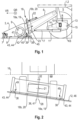
- Fig.1 shows the basic front structure of a harvesting vehicle 1 designed as a combine harvester 2 with an attachment 3, which in the illustrated embodiment is designed as a grain cutter 4. This is suspended from the machine housing 5 (not explained in more detail) in a manner to be explained in more detail.
- the inclined conveyor 6 is rotatably mounted on the machine housing 5 transversely to the forward direction VR of the harvesting vehicle 1.
- the inclined conveyor 6 conveys the crop 7 to the threshing mechanism (not shown).
- the main driving axle 10 of the harvesting vehicle 1 is rigidly connected to the machine housing 5.
- the running wheels 11 are mounted on the main driving axle 10 in a height-adjustable manner, so that a horizontal alignment of the units mounted in the machine housing 5 is possible for harvesting on a slope 12.
- the harvesting vehicle 1 is equipped with two wheel drives 13, which are pivotably connected to the ends of the main driving axle 10 via brackets KS.
- Piston-cylinder units 14 are supported on the brackets KS, the piston rods of which engage the wheel drives 13, which in turn can be pivoted about fixed axes 15 in the brackets.
- the adjustment of the running wheels 11 takes place automatically and is not explained in more detail.
- Fig.2 shows a schematic front view of the combine harvester 2 on the slope 12. If the combine harvester 2 travels in an inclined position, the piston-cylinder units 14 are controlled in order to hold the machine housing 5 in the horizontal starting position 16 by pivoting the running wheels 11. The attachment 3 and the inclined conveyor 6 are raised or lowered by the piston-cylinder units 17, which are attached on one side to the inclined conveyor 6 and on the other side in the area of the main driving axis 10.
- the attachment 3 is coupled via a swinging device 18.
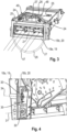
- the swinging device 18 consists of a pendulum frame 18a attachment-side frame structure 19 and a harvester-side frame structure 20 designed as a tilting frame 18b, which Fig.3 in a front view.
- the pendulum frame 18a is pivotably mounted relative to the tilting frame 18b about a virtual pendulum axis 21 extending approximately in the forward direction VR and allows the attachment 3 to pendulum relative to the inclined conveyor 6 about the virtual pendulum axis 21.
- the tilting frame 18b is mounted on the inclined conveyor 6 with a piston-cylinder unit 22 so as to be pivotable about a lower transverse axis 23, so that the cutting angle of the attachment 3 can be adjusted in the longitudinal direction of the machine.
- the tilting frame 18b holds two support rollers 24 in the upper area, which can be rotated about their axes 25 extending parallel to the direction of the virtual pendulum axis 21.
- a support element 26 rests on the support rollers 24, which extends along a circular path 27, which in turn is arranged concentrically to the virtual pendulum axis 21 and is connected to the pendulum frame 18a.
- the described arrangement of the support rollers 24 enables the pendulum frame 18a to pendulum around the virtual pendulum axis 21.
- two support rollers 24 are mounted on the tilting frame 18b symmetrically to the longitudinal center plane 28 of the tilting frame 18b on a circular path 29 extending concentrically to the virtual pendulum axis 21.
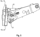
- Fig.4 shows a support roller 30 which is mounted laterally in the lower area of the tipping frame 18b and can be rotated about its axis 31 extending transversely to the direction of the virtual pendulum axis 21.
- the support roller 30 rests on the pendulum frame 18a and supports it during a pendulum movement 32 in the forward direction VR of the harvesting vehicle 1, so that direct contact of the pendulum frame 18a with the tipping frame 18b is avoided and the resulting friction moment between the pendulum frame 18a and the tipping frame 18b is low.
- two support rollers 30 are mounted on the tipping frame 18b symmetrically to the longitudinal center plane 28 of the tipping frame 18b on a circular path extending concentrically to the virtual pendulum axis 21.
- Fig.4 also shows a guide roller 33 which is mounted laterally in the lower area of the pendulum frame 18a so as to be rotatable about its axis 34 which extends parallel to the direction of the virtual pendulum axis 21.
- the guide roller 33 is operatively connected to an outer surface 35 of the tilting frame 18b which extends in the forward direction VR, so that during a pendulum movement 32 the pendulum frame 18a is guided about the virtual pendulum axis 21.
- two guide rollers 33 are mounted on the pendulum frame 18a symmetrically to the longitudinal center plane 36 of the pendulum frame 18a on a circular path which extends concentrically to the virtual pendulum axis 21.
- a pivot cylinder 37 is attached between the pendulum frame 18a and the tilting frame 18b, so that the pivot cylinder 37 can actively pivot the pendulum frame 18a relative to the tilting frame 18b about the virtual pendulum axis 21. This is in the floating position during operation, so that the front attachment 3 is attached to the harvesting vehicle 1 in a freely swinging manner.
- the transverse compensation which describes the pivoting of the attachment 3 about the virtual pendulum axis 21 to adapt the position of the attachment 3 to ground contours, is carried out during operation by two height-adjustable support wheels 38.
- two brackets 39 are attached to the attachment 3 so that they can pivot about an axis 40 extending transversely to the forward direction VR.
- the brackets 39 are attached in the outer area of the attachment 3 and are arranged symmetrically to the longitudinal center plane 41 of the attachment 3, which in the exemplary embodiment corresponds to the longitudinal center plane 36 of the pendulum frame 18a.
- the bracket 39 is pivoted by means of a hydraulic cylinder 42 which is attached to the attachment 3 and the bracket 39.
- the hydraulic cylinders 42 are controlled by means of sensors 43, with which the ground clearance of the attachment 3 is continuously measured in a manner known per se.
- the sensors 43 are pivotable floor sensors 44.
- the support wheels 38 are attached to the bracket 39 so that they can rotate around an axis 45 extending transversely to the forward direction VR in the outer area of the attachment 3.
- the support wheels 38 are guided over the floor 46 during operation and are guided by the sensor signal of the Ground sensor 44 is aligned so that the position of the attachment 3 is adapted to existing ground contours.
- the front attachment 3 is usually raised by means of the piston-cylinder unit 17 so that there is no contact between the support wheels 38 and the ground 46.
- the swivel cylinder 37 is locked in this state so that a pendulum movement 32 of the front attachment 3 is avoided.
Landscapes
- Life Sciences & Earth Sciences (AREA)
- Environmental Sciences (AREA)
- Harvester Elements (AREA)
Claims (10)
- Véhicule de récolte (1) comprenant un outil frontal (3) et un dispositif de basculement (18) pour la suspension pendulaire de l'outil frontal (3) sur le véhicule de récolte (1), comportant au moins deux rouleaux de support (24) qui sont chacun montés tournants autour d'un axe (25) s'étendant dans le sens d'avancement (VR) du véhicule de récolte (1), comportant un élément d'appui (26) qui s'étend transversalement au sens d'avancement (VR) et sur lequel sont en appui les rouleaux de support (24),l'élément d'appui (26) étant réalisé en forme d'arc, et les rouleaux de support (24) étant en liaison fonctionnelle avec l'élément d'appui (26), le dispositif de basculement (18) comportant au moins deux autres rouleaux de soutien (30) qui sont chacun montés tournants autour d'un axe (31), s'étendant dans la direction transversale (QR) du véhicule de récolte (1), et soutiennent l'outil frontal (3) dans le sens d'avancement (VR) du véhicule de récolte (1), de manière à ce que le couple de frottement entre l'outil frontal (3) et le véhicule de récolte (1) diminue.
caractérisé en ce quele dispositif de basculement (18) est constitué d'une structure de cadre (19) côté outil frontal, réalisée comme cadre pendulaire (18a), et d'une structure de cadre (20) côté véhicule de récolte, réalisée comme cadre basculant (18b), sachant que pour le pivotement actif de l'outil frontal (3) autour de l'axe pendulaire (21), un vérin de pivotement (37) est fixé entre le cadre pendulaire (18a) et le cadre basculant (18b), de sorte que le vérin de pivotement (37) peut faire pivoter le cadre pendulaire (18a) activement autour de l'axe pendulaire virtuel (21) par rapport au cadre basculant (18), le vérin de pivotement (37) se trouvant dans une position flottante pendant le service de travail, de sorte que l'outil frontal (3) est fixé de manière librement oscillante au véhicule de récolte (1). - Véhicule de récolte (1) selon la revendication 1, caractérisé en ce que l'élément d'appui (26) est associé à la structure de cadre (19) côté outil frontal, la structure de cadre (19) côté outil frontal étant accouplée à la structure de cadre (20) côté véhicule de récolte, et'élément d'appui (26) étant disposé de manière concentrique à un axe pendulaire virtuel (21) sur la structure de cadre (19) côté outil frontal.
- Véhicule de récolte (1) selon une des revendications 1 à 2, caractérisé en ce que l'axe pendulaire virtuel (21) se trouve dans la région du flux de matières (47).
- Véhicule de récolte (1) selon une des revendications 1 à 3, caractérisé en ce que les rouleaux de support (24) sont disposés sur la structure de cadre (20) côté véhicule de récolte, de manière symétrique par rapport au plan médian longitudinal (28) de la structure de cadre (20) côté véhicule de récolte et de préférence de manière concentrique à l'axe pendulaire virtuel (21), les rouleaux de support (24) étant associés à l'élément d'appui (26), dans les zones d'extrémité (48) de celui-ci.
- Véhicule de récolte (1) selon une des revendications 1 à 4, caractérisé en ce que les rouleaux de soutien (30) sont disposés sur la structure de cadre (20) côté véhicule de récolte de manière concentrique à l'axe pendulaire virtuel (21) et de préférence de manière symétrique par rapport au plan médian longitudinal (28) de la structure de cadre (20) côté véhicule de récolte.
- Véhicule de récolte (1) selon une des revendications 1 à 5, caractérisé en ce que l'on utilise en outre au moins deux rouleaux de guidage (33) qui sont chacun montés sur la structure de cadre (19) côté outil frontal, avec possibilité de rotation autour d'un axe (34) s'étendant dans le sens d'avancement (VR), et sont chacun en liaison fonctionnelle avec une surface extérieure (35) de la structure de cadre (20) côté véhicule de récolte, qui s'étend dans le sens d'avancement (VR).
- Véhicule de récolte (1) selon la revendication 6, caractérisé en ce que la surface (35) respective, avec laquelle le rouleau de guidage (33) respectif est en liaison fonctionnelle, est concentrique à l'axe pendulaire virtuel (21).
- Véhicule de récolte (1) selon une des revendications 6 à 7, caractérisé en ce que les rouleaux de guidage (33) sont disposés de manière symétrique par rapport au plan médian longitudinal (36) de la structure de cadre (20) côté véhicule de récolte et de préférence de manière concentrique à l'axe pendulaire virtuel (21).
- Véhicule de récolte (1) selon une des revendications 1 à 8, caractérisé en ce que le dispositif de basculement (18) peut être retiré du véhicule de récolte (1) en même temps que l'outil frontal (3).
- Véhicule de récolte (1) selon une des revendications 1 à 8, caractérisé en ce que les rouleaux de support (24) ainsi que les éléments d'appui (26) guidés sur ceux-ci se situent dans une région supérieure du dispositif de basculement (18), et les rouleaux de guidage (33) et les rouleaux de soutien (30) se situent dans une région latérale inférieure du dispositif de basculement (18).
Applications Claiming Priority (1)
| Application Number | Priority Date | Filing Date | Title |
|---|---|---|---|
| DE102019111587.6A DE102019111587A1 (de) | 2019-05-06 | 2019-05-06 | Mähdrescher-Einzugskanal mit rollengelagertem, Pendelkoppelrahmen sowie Verfahren zum passiven Querausgleich |
Publications (2)
| Publication Number | Publication Date |
|---|---|
| EP3735817A1 EP3735817A1 (fr) | 2020-11-11 |
| EP3735817B1 true EP3735817B1 (fr) | 2024-09-11 |
Family
ID=69570600
Family Applications (1)
| Application Number | Title | Priority Date | Filing Date |
|---|---|---|---|
| EP20156505.8A Active EP3735817B1 (fr) | 2019-05-06 | 2020-02-11 | Canal d'alimentation de moissonneuse-batteuse pourvu d'un châssis de couplage pendulaire monté sur rouleaux ainsi que procédé de compensation transversale passive |
Country Status (2)
| Country | Link |
|---|---|
| EP (1) | EP3735817B1 (fr) |
| DE (1) | DE102019111587A1 (fr) |
Families Citing this family (3)
| Publication number | Priority date | Publication date | Assignee | Title |
|---|---|---|---|---|
| DE102021123337A1 (de) | 2021-09-09 | 2023-03-09 | Claas Selbstfahrende Erntemaschinen Gmbh | Selbstfahrende Erntemaschine mit einer höhenverstellbaren Aufnahmevorrichtung |
| DE102022104295B4 (de) | 2022-02-23 | 2025-09-18 | Claas Saulgau Gmbh | Landwirtschaftliches Erntefahrzeug |
| US12532808B2 (en) | 2022-06-24 | 2026-01-27 | Cnh Industrial America Llc | Passive header tilt control for rigid-mode operation with friction-controlling cylinders |
Citations (1)
| Publication number | Priority date | Publication date | Assignee | Title |
|---|---|---|---|---|
| EP1145619B1 (fr) * | 2000-04-12 | 2004-11-03 | CLAAS Selbstfahrende Erntemaschinen GmbH | Machine de récolte pour travail sur pente |
Family Cites Families (5)
| Publication number | Priority date | Publication date | Assignee | Title |
|---|---|---|---|---|
| US2780903A (en) * | 1952-12-22 | 1957-02-12 | Deere & Co | Platform adjusting means for sidehill harvesters |
| US2904949A (en) * | 1957-09-19 | 1959-09-22 | Roy L Bell | Header support mechanism for harvesters |
| FR2781117A1 (fr) * | 1998-07-16 | 2000-01-21 | Bmv | Equipement d'ensileuse |
| DE102006030508B4 (de) | 2006-07-01 | 2014-05-08 | Maschinenfabrik Kemper Gmbh & Co. Kg | Anordnung zur pendelnden Aufhängung eines Erntevorsatzes an einer Erntemaschine |
| US10531607B2 (en) * | 2013-07-31 | 2020-01-14 | Cnh Industrial America Llc | Header lateral tilt control with automatic operation in free float and controlled tilt modes |
-
2019
- 2019-05-06 DE DE102019111587.6A patent/DE102019111587A1/de not_active Withdrawn
-
2020
- 2020-02-11 EP EP20156505.8A patent/EP3735817B1/fr active Active
Patent Citations (1)
| Publication number | Priority date | Publication date | Assignee | Title |
|---|---|---|---|---|
| EP1145619B1 (fr) * | 2000-04-12 | 2004-11-03 | CLAAS Selbstfahrende Erntemaschinen GmbH | Machine de récolte pour travail sur pente |
Also Published As
| Publication number | Publication date |
|---|---|
| DE102019111587A1 (de) | 2020-11-12 |
| EP3735817A1 (fr) | 2020-11-11 |
Similar Documents
| Publication | Publication Date | Title |
|---|---|---|
| EP4147563B1 (fr) | Moissonneuse dotée d'une tête réglable en hauteur | |
| EP2732689B1 (fr) | Barre de coupe | |
| EP1145619B1 (fr) | Machine de récolte pour travail sur pente | |
| EP3735817B1 (fr) | Canal d'alimentation de moissonneuse-batteuse pourvu d'un châssis de couplage pendulaire monté sur rouleaux ainsi que procédé de compensation transversale passive | |
| EP2529614B1 (fr) | Combinaison de mécanisme de tonte | |
| DE102014009161A1 (de) | Schneidwerk mit Mittelteil und dazu verstellbaren Seitenteilen | |
| DE10234741A1 (de) | Anlenkung eines Seitenmähwerks und seiner Zusatzeinrichtungen an ein Tragwerk zur Ankopplung an einen Traktor oder an ein Trägerfahrzeug | |
| EP4162789B1 (fr) | Méthode d'utilisation d'une tête de récolte monté sur une structure de fixation d'une moissonneuse-batteuse automotrice ainsi que moissonneuse-batteuse automotrice avec une tête de récolte segmentée | |
| DE1938698C3 (de) | Fahrbare landwirtschaftliche Erntemaschine | |
| DE4440825A1 (de) | Vorrichtung zum Mähen, Vertikutieren und/oder Aufsammeln | |
| DE2632002C2 (de) | Mähmaschine | |
| EP4030886B1 (fr) | Appareil de coupe doté d'éléments de coupe montés de manière élastique en hauteur | |
| EP0566033B1 (fr) | Cadre support pour machine de récolte, en particulier faucheuse rotative | |
| EP4049527B1 (fr) | Coupe-rubans | |
| EP1154681A1 (fr) | Faucheuse-conditionneuse | |
| DE8817108U1 (de) | Vorrichtung zum Ernten von Feldfrüchten, insbesondere Rüben | |
| DE4228584C1 (de) | Selbstfahrende zweiachsige, mehrreihige Rübenerntemaschine | |
| DE102004058116A1 (de) | Erntemaschine | |
| EP3058804A1 (fr) | Faneuse | |
| EP3025577A1 (fr) | Andaineur universel | |
| DE102018116213A1 (de) | Schneidwerk für eine landwirtschaftliche Arbeitsmaschine sowie Verfahren zu dessen Bedienung | |
| EP4124221B1 (fr) | Machine agricole et combinaison de machines agricoles | |
| DE102018116232A1 (de) | Schneidwerk für eine landwirtschaftliche Arbeitsmaschine sowie Verfahren zur Einstellung eines Schneidwerks | |
| DE3922260C2 (de) | Selbstfahrender Mähdrescher | |
| EP4454446A1 (fr) | Moissonneuse à montage frontal |
Legal Events
| Date | Code | Title | Description |
|---|---|---|---|
| PUAI | Public reference made under article 153(3) epc to a published international application that has entered the european phase |
Free format text: ORIGINAL CODE: 0009012 |
|
| STAA | Information on the status of an ep patent application or granted ep patent |
Free format text: STATUS: THE APPLICATION HAS BEEN PUBLISHED |
|
| AK | Designated contracting states |
Kind code of ref document: A1 Designated state(s): AL AT BE BG CH CY CZ DE DK EE ES FI FR GB GR HR HU IE IS IT LI LT LU LV MC MK MT NL NO PL PT RO RS SE SI SK SM TR |
|
| AX | Request for extension of the european patent |
Extension state: BA ME |
|
| STAA | Information on the status of an ep patent application or granted ep patent |
Free format text: STATUS: REQUEST FOR EXAMINATION WAS MADE |
|
| 17P | Request for examination filed |
Effective date: 20210511 |
|
| RBV | Designated contracting states (corrected) |
Designated state(s): AL AT BE BG CH CY CZ DE DK EE ES FI FR GB GR HR HU IE IS IT LI LT LU LV MC MK MT NL NO PL PT RO RS SE SI SK SM TR |
|
| STAA | Information on the status of an ep patent application or granted ep patent |
Free format text: STATUS: EXAMINATION IS IN PROGRESS |
|
| 17Q | First examination report despatched |
Effective date: 20210806 |
|
| P01 | Opt-out of the competence of the unified patent court (upc) registered |
Effective date: 20230516 |
|
| GRAP | Despatch of communication of intention to grant a patent |
Free format text: ORIGINAL CODE: EPIDOSNIGR1 |
|
| STAA | Information on the status of an ep patent application or granted ep patent |
Free format text: STATUS: GRANT OF PATENT IS INTENDED |
|
| INTG | Intention to grant announced |
Effective date: 20240408 |
|
| GRAS | Grant fee paid |
Free format text: ORIGINAL CODE: EPIDOSNIGR3 |
|
| GRAA | (expected) grant |
Free format text: ORIGINAL CODE: 0009210 |
|
| STAA | Information on the status of an ep patent application or granted ep patent |
Free format text: STATUS: THE PATENT HAS BEEN GRANTED |
|
| AK | Designated contracting states |
Kind code of ref document: B1 Designated state(s): AL AT BE BG CH CY CZ DE DK EE ES FI FR GB GR HR HU IE IS IT LI LT LU LV MC MK MT NL NO PL PT RO RS SE SI SK SM TR |
|
| REG | Reference to a national code |
Ref country code: GB Ref legal event code: FG4D Free format text: NOT ENGLISH |
|
| REG | Reference to a national code |
Ref country code: CH Ref legal event code: EP |
|
| REG | Reference to a national code |
Ref country code: DE Ref legal event code: R096 Ref document number: 502020009153 Country of ref document: DE |
|
| REG | Reference to a national code |
Ref country code: IE Ref legal event code: FG4D Free format text: LANGUAGE OF EP DOCUMENT: GERMAN |
|
| REG | Reference to a national code |
Ref country code: LT Ref legal event code: MG9D |
|
| PG25 | Lapsed in a contracting state [announced via postgrant information from national office to epo] |
Ref country code: NO Free format text: LAPSE BECAUSE OF FAILURE TO SUBMIT A TRANSLATION OF THE DESCRIPTION OR TO PAY THE FEE WITHIN THE PRESCRIBED TIME-LIMIT Effective date: 20241211 |
|
| REG | Reference to a national code |
Ref country code: NL Ref legal event code: MP Effective date: 20240911 |
|
| PG25 | Lapsed in a contracting state [announced via postgrant information from national office to epo] |
Ref country code: GR Free format text: LAPSE BECAUSE OF FAILURE TO SUBMIT A TRANSLATION OF THE DESCRIPTION OR TO PAY THE FEE WITHIN THE PRESCRIBED TIME-LIMIT Effective date: 20241212 Ref country code: FI Free format text: LAPSE BECAUSE OF FAILURE TO SUBMIT A TRANSLATION OF THE DESCRIPTION OR TO PAY THE FEE WITHIN THE PRESCRIBED TIME-LIMIT Effective date: 20240911 |
|
| PG25 | Lapsed in a contracting state [announced via postgrant information from national office to epo] |
Ref country code: BG Free format text: LAPSE BECAUSE OF FAILURE TO SUBMIT A TRANSLATION OF THE DESCRIPTION OR TO PAY THE FEE WITHIN THE PRESCRIBED TIME-LIMIT Effective date: 20240911 |
|
| PG25 | Lapsed in a contracting state [announced via postgrant information from national office to epo] |
Ref country code: LV Free format text: LAPSE BECAUSE OF FAILURE TO SUBMIT A TRANSLATION OF THE DESCRIPTION OR TO PAY THE FEE WITHIN THE PRESCRIBED TIME-LIMIT Effective date: 20240911 |
|
| PG25 | Lapsed in a contracting state [announced via postgrant information from national office to epo] |
Ref country code: HR Free format text: LAPSE BECAUSE OF FAILURE TO SUBMIT A TRANSLATION OF THE DESCRIPTION OR TO PAY THE FEE WITHIN THE PRESCRIBED TIME-LIMIT Effective date: 20240911 |
|
| PG25 | Lapsed in a contracting state [announced via postgrant information from national office to epo] |
Ref country code: RS Free format text: LAPSE BECAUSE OF FAILURE TO SUBMIT A TRANSLATION OF THE DESCRIPTION OR TO PAY THE FEE WITHIN THE PRESCRIBED TIME-LIMIT Effective date: 20241211 Ref country code: ES Free format text: LAPSE BECAUSE OF FAILURE TO SUBMIT A TRANSLATION OF THE DESCRIPTION OR TO PAY THE FEE WITHIN THE PRESCRIBED TIME-LIMIT Effective date: 20240911 |
|
| PG25 | Lapsed in a contracting state [announced via postgrant information from national office to epo] |
Ref country code: RS Free format text: LAPSE BECAUSE OF FAILURE TO SUBMIT A TRANSLATION OF THE DESCRIPTION OR TO PAY THE FEE WITHIN THE PRESCRIBED TIME-LIMIT Effective date: 20241211 Ref country code: NO Free format text: LAPSE BECAUSE OF FAILURE TO SUBMIT A TRANSLATION OF THE DESCRIPTION OR TO PAY THE FEE WITHIN THE PRESCRIBED TIME-LIMIT Effective date: 20241211 Ref country code: LV Free format text: LAPSE BECAUSE OF FAILURE TO SUBMIT A TRANSLATION OF THE DESCRIPTION OR TO PAY THE FEE WITHIN THE PRESCRIBED TIME-LIMIT Effective date: 20240911 Ref country code: HR Free format text: LAPSE BECAUSE OF FAILURE TO SUBMIT A TRANSLATION OF THE DESCRIPTION OR TO PAY THE FEE WITHIN THE PRESCRIBED TIME-LIMIT Effective date: 20240911 Ref country code: GR Free format text: LAPSE BECAUSE OF FAILURE TO SUBMIT A TRANSLATION OF THE DESCRIPTION OR TO PAY THE FEE WITHIN THE PRESCRIBED TIME-LIMIT Effective date: 20241212 Ref country code: FI Free format text: LAPSE BECAUSE OF FAILURE TO SUBMIT A TRANSLATION OF THE DESCRIPTION OR TO PAY THE FEE WITHIN THE PRESCRIBED TIME-LIMIT Effective date: 20240911 Ref country code: ES Free format text: LAPSE BECAUSE OF FAILURE TO SUBMIT A TRANSLATION OF THE DESCRIPTION OR TO PAY THE FEE WITHIN THE PRESCRIBED TIME-LIMIT Effective date: 20240911 Ref country code: BG Free format text: LAPSE BECAUSE OF FAILURE TO SUBMIT A TRANSLATION OF THE DESCRIPTION OR TO PAY THE FEE WITHIN THE PRESCRIBED TIME-LIMIT Effective date: 20240911 |
|
| PG25 | Lapsed in a contracting state [announced via postgrant information from national office to epo] |
Ref country code: NL Free format text: LAPSE BECAUSE OF FAILURE TO SUBMIT A TRANSLATION OF THE DESCRIPTION OR TO PAY THE FEE WITHIN THE PRESCRIBED TIME-LIMIT Effective date: 20240911 |
|
| PG25 | Lapsed in a contracting state [announced via postgrant information from national office to epo] |
Ref country code: PT Free format text: LAPSE BECAUSE OF FAILURE TO SUBMIT A TRANSLATION OF THE DESCRIPTION OR TO PAY THE FEE WITHIN THE PRESCRIBED TIME-LIMIT Effective date: 20250113 Ref country code: IS Free format text: LAPSE BECAUSE OF FAILURE TO SUBMIT A TRANSLATION OF THE DESCRIPTION OR TO PAY THE FEE WITHIN THE PRESCRIBED TIME-LIMIT Effective date: 20250111 |
|
| PG25 | Lapsed in a contracting state [announced via postgrant information from national office to epo] |
Ref country code: RO Free format text: LAPSE BECAUSE OF FAILURE TO SUBMIT A TRANSLATION OF THE DESCRIPTION OR TO PAY THE FEE WITHIN THE PRESCRIBED TIME-LIMIT Effective date: 20240911 Ref country code: SM Free format text: LAPSE BECAUSE OF FAILURE TO SUBMIT A TRANSLATION OF THE DESCRIPTION OR TO PAY THE FEE WITHIN THE PRESCRIBED TIME-LIMIT Effective date: 20240911 |
|
| PG25 | Lapsed in a contracting state [announced via postgrant information from national office to epo] |
Ref country code: EE Free format text: LAPSE BECAUSE OF FAILURE TO SUBMIT A TRANSLATION OF THE DESCRIPTION OR TO PAY THE FEE WITHIN THE PRESCRIBED TIME-LIMIT Effective date: 20240911 |
|
| PG25 | Lapsed in a contracting state [announced via postgrant information from national office to epo] |
Ref country code: CZ Free format text: LAPSE BECAUSE OF FAILURE TO SUBMIT A TRANSLATION OF THE DESCRIPTION OR TO PAY THE FEE WITHIN THE PRESCRIBED TIME-LIMIT Effective date: 20240911 Ref country code: PL Free format text: LAPSE BECAUSE OF FAILURE TO SUBMIT A TRANSLATION OF THE DESCRIPTION OR TO PAY THE FEE WITHIN THE PRESCRIBED TIME-LIMIT Effective date: 20240911 |
|
| PG25 | Lapsed in a contracting state [announced via postgrant information from national office to epo] |
Ref country code: SK Free format text: LAPSE BECAUSE OF FAILURE TO SUBMIT A TRANSLATION OF THE DESCRIPTION OR TO PAY THE FEE WITHIN THE PRESCRIBED TIME-LIMIT Effective date: 20240911 |
|
| REG | Reference to a national code |
Ref country code: DE Ref legal event code: R097 Ref document number: 502020009153 Country of ref document: DE |
|
| PG25 | Lapsed in a contracting state [announced via postgrant information from national office to epo] |
Ref country code: DK Free format text: LAPSE BECAUSE OF FAILURE TO SUBMIT A TRANSLATION OF THE DESCRIPTION OR TO PAY THE FEE WITHIN THE PRESCRIBED TIME-LIMIT Effective date: 20240911 |
|
| PLBE | No opposition filed within time limit |
Free format text: ORIGINAL CODE: 0009261 |
|
| STAA | Information on the status of an ep patent application or granted ep patent |
Free format text: STATUS: NO OPPOSITION FILED WITHIN TIME LIMIT |
|
| 26N | No opposition filed |
Effective date: 20250612 |
|
| PG25 | Lapsed in a contracting state [announced via postgrant information from national office to epo] |
Ref country code: SE Free format text: LAPSE BECAUSE OF FAILURE TO SUBMIT A TRANSLATION OF THE DESCRIPTION OR TO PAY THE FEE WITHIN THE PRESCRIBED TIME-LIMIT Effective date: 20240911 |
|
| PG25 | Lapsed in a contracting state [announced via postgrant information from national office to epo] |
Ref country code: MC Free format text: LAPSE BECAUSE OF FAILURE TO SUBMIT A TRANSLATION OF THE DESCRIPTION OR TO PAY THE FEE WITHIN THE PRESCRIBED TIME-LIMIT Effective date: 20240911 |
|
| REG | Reference to a national code |
Ref country code: CH Ref legal event code: PL |
|
| PG25 | Lapsed in a contracting state [announced via postgrant information from national office to epo] |
Ref country code: LU Free format text: LAPSE BECAUSE OF NON-PAYMENT OF DUE FEES Effective date: 20250211 |
|
| PG25 | Lapsed in a contracting state [announced via postgrant information from national office to epo] |
Ref country code: CH Free format text: LAPSE BECAUSE OF NON-PAYMENT OF DUE FEES Effective date: 20250228 |
|
| GBPC | Gb: european patent ceased through non-payment of renewal fee |
Effective date: 20250211 |
|
| PG25 | Lapsed in a contracting state [announced via postgrant information from national office to epo] |
Ref country code: GB Free format text: LAPSE BECAUSE OF NON-PAYMENT OF DUE FEES Effective date: 20250211 |
|
| PG25 | Lapsed in a contracting state [announced via postgrant information from national office to epo] |
Ref country code: FR Free format text: LAPSE BECAUSE OF NON-PAYMENT OF DUE FEES Effective date: 20250228 |
|
| PG25 | Lapsed in a contracting state [announced via postgrant information from national office to epo] |
Ref country code: IE Free format text: LAPSE BECAUSE OF NON-PAYMENT OF DUE FEES Effective date: 20250211 |
|
| PGFP | Annual fee paid to national office [announced via postgrant information from national office to epo] |
Ref country code: DE Payment date: 20260218 Year of fee payment: 7 |
|
| PG25 | Lapsed in a contracting state [announced via postgrant information from national office to epo] |
Ref country code: AT Free format text: LAPSE BECAUSE OF NON-PAYMENT OF DUE FEES Effective date: 20250211 |
|
| PGFP | Annual fee paid to national office [announced via postgrant information from national office to epo] |
Ref country code: BE Payment date: 20260218 Year of fee payment: 7 Ref country code: IT Payment date: 20260224 Year of fee payment: 7 |
|
| REG | Reference to a national code |
Ref country code: AT Ref legal event code: MM01 Ref document number: 1721816 Country of ref document: AT Kind code of ref document: T Effective date: 20250211 |